EP1398844A1 - Bandpass filter - Google Patents
Bandpass filter Download PDFInfo
- Publication number
- EP1398844A1 EP1398844A1 EP20030255570 EP03255570A EP1398844A1 EP 1398844 A1 EP1398844 A1 EP 1398844A1 EP 20030255570 EP20030255570 EP 20030255570 EP 03255570 A EP03255570 A EP 03255570A EP 1398844 A1 EP1398844 A1 EP 1398844A1
- Authority
- EP
- European Patent Office
- Prior art keywords
- strip line
- lines
- dielectric substrate
- bent
- bandpass filter
- Prior art date
- Legal status (The legal status is an assumption and is not a legal conclusion. Google has not performed a legal analysis and makes no representation as to the accuracy of the status listed.)
- Withdrawn
Links
- 230000005540 biological transmission Effects 0.000 claims abstract description 26
- 239000000758 substrate Substances 0.000 claims abstract description 18
- 230000008878 coupling Effects 0.000 abstract description 9
- 238000010168 coupling process Methods 0.000 abstract description 9
- 238000005859 coupling reaction Methods 0.000 abstract description 9
- 239000004020 conductor Substances 0.000 description 2
- 238000010586 diagram Methods 0.000 description 2
- 229910010293 ceramic material Inorganic materials 0.000 description 1
- 230000003247 decreasing effect Effects 0.000 description 1
Images


Classifications
-
- H—ELECTRICITY
- H01—ELECTRIC ELEMENTS
- H01P—WAVEGUIDES; RESONATORS, LINES, OR OTHER DEVICES OF THE WAVEGUIDE TYPE
- H01P1/00—Auxiliary devices
- H01P1/20—Frequency-selective devices, e.g. filters
- H01P1/201—Filters for transverse electromagnetic waves
- H01P1/203—Strip line filters
- H01P1/20327—Electromagnetic interstage coupling
- H01P1/20354—Non-comb or non-interdigital filters
- H01P1/20381—Special shape resonators
Definitions
- the present invention relates to a bandpass filter configured of strip line resonators formed on a dielectric substrate.
- Fig. 5 depicts a traditiona 1 bandpass filter.
- Strip line resonators 22, 23 and 24 are formed on the top of a dielectric substrate 21 so as to be in parallel with each other.
- the length of each of the strip line resonators 22 to 24 has nearly a half-wave length of a transmission signal, and the adjacent strip line resonators are disposed so as to be electromagnetically coupled in the portions of a half of the length each other.
- a ground conductor 25 is disposed on the underside of the dielectric substrate 21 .
- transmission lines 26 and 27 for connecting external circuits are disposed so as to be electromagnetically coupled to the strip line resonators 22 and 24 disposed on both sides, thereby configuring the bandpass filter as a whole (see, Patent Document 1).
- An object of the invention is to reduce the electromagnetic coupling of adjacent lines (lines alternately adjacent to each other) to prevent an attenuation amount from increasing on the low pass side of the passband, and to make the skirt characteristics steep as well.
- the invention has a dielectric substrate; a plurality of strip line resonators formed on the dielectric substrate as electromagnetically coupled to each other with both ends opened; and two transmission lines formed on the dielectric substrate for connecting external circuits, wherein at least one or more of the strip line resonators is bent at a center part in a length direction.
- At least two or more of the strip line resonators are bent, and lines connecting the both ends of the bent strip lines are in parallel with each other.
- the bent angle is an angle of about 90°.
- the bandpass filter according to the invention has the dielectric substrate; a plurality of the strip line resonators formed on the dielectric substrate as electromagnetically coupled to each other with the both ends opened; and two transmission lines formed on the dielectric substrate for connecting external circuit, wherein at least one or more of the strip line resonators is bent at the center part in the length direction. Accordingly, the electromagnetic coupling between the lines alternately disposed is reduced, the passband is flat, and the attenuation on the low pass side of the passband is decreased. Additionally, the skirt characteristics in the frequency band lower than the passband are steep as well.
- the entire bandpass filter can be configured linearly.
- the bent angle is an angle of about 90°. Accordingly, the electromagnetic coupling between the lines disposed alternately is most reduced.
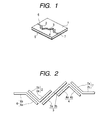
- FIG. 1 depicts a perspective view of a first embodiment
- Fig. 2 depicts a plan view of the first embodiment
- Fig. 3 depicts the transmission characteristics
- Fig. 4 depicts a plan view of a second embodiment.
- a dielectric substrate 1 i formed of a ceramic material with small dielectric loss, for example, and a plurality of strip line resonators 2, 3 and 4 (three in Fig. 1) is formed on the top thereof.
- the length of each of the strip line resonators 2 to 4 has nearly a half-wave length of a transmission signal, and the adjacent strip line resonators are so as to be electromagnetically coupled in the portions of a half of the length each other.
- a ground conductor 5 is disposed on the underside of the dielectric substrate 1.
- transmission lines 6 and 7 for connecting external circuits are disposed so as to be electromagnetically coupled to the strip line resonators 2 and 4 disposed on both sides, thereby configuring the bandpass filter as a whole. Signals are inputted to one of the transmission lines 6 and 7, and are outputted from the other.
- Fig. 2 depicts a plan form of the strip line resonators 2, 3 and 4 and the transmission lines 6 and 7 for connecting external circuits, all formed on the dielectric substrate 1.
- the length of each of the strip line resonators 2 to 4 opened at the both ends thereof is set to have nearly a half-wave length of a transmission signal, and the first strip line resonator 2 and the third strip line resonator 4 are bent at the position of the center of the length at an angle of 90°.
- the line connecting the both ends of the first strip line resonator 2 and the line connecting the both ends of the third strip line resonator 4 are disposed in parallel, and the bent directions thereof are oriented in the directions opposite to each other.
- the linear second strip line resonator 3 is disposed between the first strip line resonator 2 and the third strip line resonator 4.
- a linear part 3a one side from the center position of the length to one end, faces a linear part 2a in parallel, one side of the bent first strip line resonator 2, and a linear part 3b, the other side from the center position to the other end, faces a linear part 4a in parallel, one side of the bent third strip line resonator 4. Therefore, the three strip line resonators 2 to 4 are disposed almost linearly as a whole.
- the first transmission line 6 is bent in an elbow shape, and a linear part 6a, one side thereof, faces a linear part 2b in parallel, the other side of the first strip line resonator 2.
- the second transmission line 7 is also bent in an elbow shape, and a linear part 7a, one side thereof, faces a linear part 4b in parallel, the other of the third strip line resonator 4. Then, signals are inputted to a linear part 6b, the other of the first transmission line 6, or a linear part 7b, the other of the second transmission line 7 , and the signals transmitted through each of the strip line resonators 2 to 4 are outputted from the other.
- electromagnetic coupling between two lines having the alternate relationship is weakened including the transmission lines 6 and 7 for inputting and outputting signals.
- the linear part 6a, one side of the first transmission line 6, and the second strip line resonator 3 are perpendicular to each other in the linear directions thereof. Therefore, the electromagnetic coupling is weakened. It is the same in the relationship between the second strip line resonator 3 and the second transmission line 7.
- the linear part 2a, one side of the first strip line resonator 2, and the linear part 4a, the other side of the third strip line resonator 4 are in parallel with each other. However, since there are no portions facing each other in the linear directions thereof, the electromagnetic coupling to each other is weakened.
- Fig. 4 depicts an embodiment that all of strip line resonators are bent, having the configuration in which the second strip line resonator 3 in Fig. 2 is bent at an angle of about 90° in the center part thereof.
- a linear part 2a, one side of the first strip line resonator 2 and a linear part 4a, one side of the third strip line resonator 4 are perpendicular to each other in the linear directions thereof. Therefore, the electromagnetic coupling is weakened. Accordingly, the transmission characteristics as shown in Fig. 3 are shown in Fig. 4 as well.
- bent angle of the strip line resonators is desirably at an angle of 90 °, but it is not necessarily defined at an angle of 90°.
Landscapes
- Physics & Mathematics (AREA)
- Electromagnetism (AREA)
- Control Of Motors That Do Not Use Commutators (AREA)
Abstract
The electromagnetic coupling of adjacent lines (lines
alternately adjacent to each other) is to be reduced to prevent
an attenuation amount from increasing on the low pass side of
a passband, and the skirt characteristics are to be steep. A
dielectric substrate (1); a plurality of strip line
resonators (2, 3, 4) formed on the dielectric substrate as
electromagnetically coupled to each other with the both ends
opened; and two transmission lines (6, 7) formed on the
dielectric substrate for connecting external circuits are
provided, in which at least one or more of the strip line
resonators is bent at the center part in the length
direction. Therefore, the electromagnetic coupling between
the lines disposed alternately is reduced, the passband is
flat, and the skirt characteristics in the frequency band
lower than the passband are steep.
Description
- The present invention relates to a bandpass filter configured of strip line resonators formed on a dielectric substrate.
- Fig. 5 depicts a
traditiona 1 bandpass filter.Strip line resonators dielectric substrate 21 so as to be in parallel with each other. The length of each of thestrip line resonators 22 to 24 has nearly a half-wave length of a transmission signal, and the adjacent strip line resonators are disposed so as to be electromagnetically coupled in the portions of a half of the length each other. In addition, aground conductor 25 is disposed on the underside of thedielectric substrate 21 . Then,transmission lines strip line resonators 22 and 24 disposed on both sides, thereby configuring the bandpass filter as a whole (see, Patent Document 1). - JP-A-5-121903 (Fig. 2)
- In the traditional bandpass filter descried above, since each of the strip line resonators and the transmission lines are in parallel with each other, the adjacent lines including the transmission lines (the lines alternately adjacent to each other) are also electromagneticcally coupled to deteriorate the passband characteristics. As shown in Fig. 6, there are problems that attenuation R on the low pass side is greater than that on the high pass side of the passband and the skirt characteristics are gentle as well.
- An object of the invention is to reduce the electromagnetic coupling of adjacent lines (lines alternately adjacent to each other) to prevent an attenuation amount from increasing on the low pass side of the passband, and to make the skirt characteristics steep as well.
- As a means for solving the problems, the invention has a dielectric substrate; a plurality of strip line resonators formed on the dielectric substrate as electromagnetically coupled to each other with both ends opened; and two transmission lines formed on the dielectric substrate for connecting external circuits, wherein at least one or more of the strip line resonators is bent at a center part in a length direction.
- Preferably, at least two or more of the strip line resonators are bent, and lines connecting the both ends of the bent strip lines are in parallel with each other.
- Preferably, the bent angle is an angle of about 90°.
- As described above, the bandpass filter according to the invention has the dielectric substrate; a plurality of the strip line resonators formed on the dielectric substrate as electromagnetically coupled to each other with the both ends opened; and two transmission lines formed on the dielectric substrate for connecting external circuit, wherein at least one or more of the strip line resonators is bent at the center part in the length direction. Accordingly, the electromagnetic coupling between the lines alternately disposed is reduced, the passband is flat, and the attenuation on the low pass side of the passband is decreased. Additionally, the skirt characteristics in the frequency band lower than the passband are steep as well.
- Furthermore, at least two or more of the strip line resonators are bent, and the lines connecting the both ends of the bent strip lines are in parallel with each other. Accordingly, the entire bandpass filter can be configured linearly.
- Moreover, the bent angle is an angle of about 90°. Accordingly, the electromagnetic coupling between the lines disposed alternately is most reduced.
- Embodiments of the invention will now be described, by way of example only, with reference to the accompanying drawings, in which:
- Fig. 1 is a perspective view illustrating a bandpass filter according to the invention;
- Fig. 2 is a plan view illustrating a first embodiment of the bandpass filter according to the invention;
- Fig. 3 is a diagram illustrating the transmission characteristics of the bandpass filter according to the invention;
- Fig. 4 is a plan view illustrating the first embodiment of the bandpass filter according to the invention;
- Fig. 5 is a perspective view illustrating the traditional bandpass filter; and
- Fig. 6 is a diagram illustrating the transmission characteristics of the traditional bandpass filter.
-
- A bandpass filter according to the invention will be described in accordance with Figs. 1 to 4. Fig. 1 depicts a perspective view of a first embodiment, Fig. 2 depicts a plan view of the first embodiment, Fig. 3 depicts the transmission characteristics, and Fig. 4 depicts a plan view of a second embodiment.
- First, in Fig. 1, a
dielectric substrate 1 i s formed of a ceramic material with small dielectric loss, for example, and a plurality ofstrip line resonators strip line resonators 2 to 4 has nearly a half-wave length of a transmission signal, and the adjacent strip line resonators are so as to be electromagnetically coupled in the portions of a half of the length each other. In addition, a ground conductor 5 is disposed on the underside of thedielectric substrate 1. Then,transmission lines strip line resonators transmission lines - Fig. 2 depicts a plan form of the
strip line resonators transmission lines dielectric substrate 1. The length of each of thestrip line resonators 2 to 4 opened at the both ends thereof is set to have nearly a half-wave length of a transmission signal, and the firststrip line resonator 2 and the thirdstrip line resonator 4 are bent at the position of the center of the length at an angle of 90°. Then, the line connecting the both ends of the firststrip line resonator 2 and the line connecting the both ends of the thirdstrip line resonator 4 are disposed in parallel, and the bent directions thereof are oriented in the directions opposite to each other. - The linear second
strip line resonator 3 is disposed between the firststrip line resonator 2 and the thirdstrip line resonator 4. Alinear part 3a, one side from the center position of the length to one end, faces alinear part 2a in parallel, one side of the bent firststrip line resonator 2, and alinear part 3b, the other side from the center position to the other end, faces alinear part 4a in parallel, one side of the bent thirdstrip line resonator 4. Therefore, the threestrip line resonators 2 to 4 are disposed almost linearly as a whole. - The
first transmission line 6 is bent in an elbow shape, and alinear part 6a, one side thereof, faces alinear part 2b in parallel, the other side of the firststrip line resonator 2. Moreover, thesecond transmission line 7 is also bent in an elbow shape, and alinear part 7a, one side thereof, faces alinear part 4b in parallel, the other of the thirdstrip line resonator 4. Then, signals are inputted to alinear part 6b, the other of thefirst transmission line 6, or alinear part 7b, the other of thesecond transmission line 7 , and the signals transmitted through each of thestrip line resonators 2 to 4 are outputted from the other. - In the configuration, electromagnetic coupling between two lines having the alternate relationship is weakened including the
transmission lines first transmission line 6 and the secondstrip line resonator 3, thelinear part 6a, one side of thefirst transmission line 6, and the secondstrip line resonator 3 are perpendicular to each other in the linear directions thereof. Therefore, the electromagnetic coupling is weakened. It is the same in the relationship between the secondstrip line resonator 3 and thesecond transmission line 7. - Additionally, in the relationship between the first
strip line resonator 2 and the thirdstrip line resonator 4, thelinear part 2a, one side of the firststrip line resonator 2, and thelinear part 4a, the other side of the thirdstrip line resonator 4, are in parallel with each other. However, since there are no portions facing each other in the linear directions thereof, the electromagnetic coupling to each other is weakened. - Consequently, in the transmission characteristics, the attenuation on the low pass side of the passband is reduced, and the whole passband has nearly flat characteristics as shown in Fig. 3.
- Fig. 4 depicts an embodiment that all of strip line resonators are bent, having the configuration in which the second
strip line resonator 3 in Fig. 2 is bent at an angle of about 90° in the center part thereof. In this case, in the relationship between a firststrip line resonator 2 and a thirdstrip line resonator 4, alinear part 2a, one side of the firststrip line resonator 2 and alinear part 4a, one side of the thirdstrip line resonator 4, are perpendicular to each other in the linear directions thereof. Therefore, the electromagnetic coupling is weakened. Accordingly, the transmission characteristics as shown in Fig. 3 are shown in Fig. 4 as well. - Furthermore, the bent angle of the strip line resonators is desirably at an angle of 90 °, but it is not necessarily defined at an angle of 90°.
Claims (3)
- A bandpass filter characterized by comprising:wherein at least one or more of the strip line resonators is bent at a center part in a length direction.a dielectric substrate;a plurality of strip line resonators formed on the dielectric substrate as electromagnetically coupled to each other with both ends opened; andtwo transmission lines formed on the dielectric substrate for connecting external circuits,
- The bandpass filter according to claim 1, characterized in that at least two or more of the strip line resonators are bent, and lines connecting the both ends of the bent strip lines are in parallel with each other.
- The bandpass filter according to claim 1 or 2, characterized in that the bent angle is an angle of about 90°.
Applications Claiming Priority (2)
| Application Number | Priority Date | Filing Date | Title |
|---|---|---|---|
| JP2002265653 | 2002-09-11 | ||
| JP2002265653A JP2004104588A (en) | 2002-09-11 | 2002-09-11 | Bandpass filter |
Publications (1)
| Publication Number | Publication Date |
|---|---|
| EP1398844A1 true EP1398844A1 (en) | 2004-03-17 |
Family
ID=31884776
Family Applications (1)
| Application Number | Title | Priority Date | Filing Date |
|---|---|---|---|
| EP20030255570 Withdrawn EP1398844A1 (en) | 2002-09-11 | 2003-09-06 | Bandpass filter |
Country Status (2)
| Country | Link |
|---|---|
| EP (1) | EP1398844A1 (en) |
| JP (1) | JP2004104588A (en) |
Cited By (2)
| Publication number | Priority date | Publication date | Assignee | Title |
|---|---|---|---|---|
| KR100598867B1 (en) | 2004-12-28 | 2006-07-12 | 전자부품연구원 | Microstrip Transmission Line with Filter |
| US8847704B2 (en) | 2011-03-25 | 2014-09-30 | Murata Manufacturing Co., Ltd. | Electronic component |
Families Citing this family (1)
| Publication number | Priority date | Publication date | Assignee | Title |
|---|---|---|---|---|
| TWI492446B (en) | 2010-11-19 | 2015-07-11 | Murata Manufacturing Co | Electronic Parts |
Citations (2)
| Publication number | Priority date | Publication date | Assignee | Title |
|---|---|---|---|---|
| SU1350703A1 (en) * | 1985-11-29 | 1987-11-07 | Московский Электротехнический Институт Связи | Bandpass filter |
| EP0371446A2 (en) * | 1988-11-28 | 1990-06-06 | Fujitsu Limited | Band pass filter |
-
2002
- 2002-09-11 JP JP2002265653A patent/JP2004104588A/en not_active Withdrawn
-
2003
- 2003-09-06 EP EP20030255570 patent/EP1398844A1/en not_active Withdrawn
Patent Citations (2)
| Publication number | Priority date | Publication date | Assignee | Title |
|---|---|---|---|---|
| SU1350703A1 (en) * | 1985-11-29 | 1987-11-07 | Московский Электротехнический Институт Связи | Bandpass filter |
| EP0371446A2 (en) * | 1988-11-28 | 1990-06-06 | Fujitsu Limited | Band pass filter |
Non-Patent Citations (3)
| Title |
|---|
| BHASIN K B: "PERFORMANCE OF A Y-BA-CU-O SUPERCONDUCTING FILTER/GAAS LOW NOISE AMPLIFIER HYBRID CIRCUIT", INTERNATIONAL MICROWAVE SYMPOSIUM DIGEST (MTT-S). ALBUQUERQUE, JUNE 1 - 5, 1992, NEW YORK, IEEE, US, vol. 1, 1 June 1992 (1992-06-01), pages 481 - 483, XP000332760 * |
| G. OHM ET AL.: "750 MHZ MICROSTRIP BANDPASS FILTER ON BARIUM TETRATITANATE SUBSTRATE", ELECTRONICS LETTERS., vol. 18, no. 15, 22 July 1982 (1982-07-22), IEE STEVENAGE., GB, pages 661 - 63, XP002266791, ISSN: 0013-5194 * |
| SOVIET INVENTIONS ILLUSTRATED Section EI Week 8822, 2 June 1988 Derwent World Patents Index; Class W02, AN 8815425422, XP002065019 * |
Cited By (2)
| Publication number | Priority date | Publication date | Assignee | Title |
|---|---|---|---|---|
| KR100598867B1 (en) | 2004-12-28 | 2006-07-12 | 전자부품연구원 | Microstrip Transmission Line with Filter |
| US8847704B2 (en) | 2011-03-25 | 2014-09-30 | Murata Manufacturing Co., Ltd. | Electronic component |
Also Published As
| Publication number | Publication date |
|---|---|
| JP2004104588A (en) | 2004-04-02 |
Similar Documents
| Publication | Publication Date | Title |
|---|---|---|
| EP1278264A1 (en) | Dielectric waveguide filter and mounting structure thereof | |
| US6262640B1 (en) | Coplanar line filter and duplexer | |
| CA2379262A1 (en) | Directional coupler | |
| US4488130A (en) | Microwave integrated circuit, bandpass filter | |
| JPH03212001A (en) | Dielectric filter | |
| JPS62164301A (en) | Strip line filter | |
| US7825752B2 (en) | Dielectric filter having a dielectric block with input/output electrodes of a bent shape at corner portions of the block | |
| JP2005117433A (en) | Filter | |
| EP0301789B1 (en) | 1/2 wavelength side coupling filter | |
| KR20020006490A (en) | Dual-mode band-pass filter | |
| JPH04167701A (en) | Dielectric filter | |
| JP2004104588A (en) | Bandpass filter | |
| US6535078B1 (en) | Dielectric filter, dielectric duplexer, and communication system | |
| US7782157B2 (en) | Resonant circuit, filter circuit, and multilayered substrate | |
| JPS63283201A (en) | Integrally molded type high frequency filter | |
| JPS62278801A (en) | microstrip bandpass filter | |
| EP1204205A2 (en) | Lattice filter with ripple in passing band eliminated and with passing band widened | |
| JPH0478202B2 (en) | ||
| JPS60123102A (en) | Extra-high frequency filter | |
| JPS63300606A (en) | Directional coupler | |
| JPS62217701A (en) | Branching filter | |
| JP2010199899A (en) | Filter | |
| JP2001185905A (en) | Dielectric filter | |
| JP2597116Y2 (en) | Coaxial bandpass filter | |
| JPH03181204A (en) | Band-pass filter |
Legal Events
| Date | Code | Title | Description |
|---|---|---|---|
| PUAI | Public reference made under article 153(3) epc to a published international application that has entered the european phase |
Free format text: ORIGINAL CODE: 0009012 |
|
| AK | Designated contracting states |
Kind code of ref document: A1 Designated state(s): AT BE BG CH CY CZ DE DK EE ES FI FR GB GR HU IE IT LI LU MC NL PT RO SE SI SK TR |
|
| AX | Request for extension of the european patent |
Extension state: AL LT LV MK |
|
| 17P | Request for examination filed |
Effective date: 20040315 |
|
| AKX | Designation fees paid |
Designated state(s): DE FR GB |
|
| 17Q | First examination report despatched |
Effective date: 20070418 |
|
| STAA | Information on the status of an ep patent application or granted ep patent |
Free format text: STATUS: THE APPLICATION IS DEEMED TO BE WITHDRAWN |
|
| 18D | Application deemed to be withdrawn |
Effective date: 20070829 |