FIELD OF THE INVENTION
-
This invention relates generally to machines and
procedures for incremental printing of text or graphic
images; and more particularly to removal of artifacts in
liquid-colorant printing that constructs such images from
individual colorant spots, formed in a two-dimensional
pixel array on a printing medium such as paper, transparency
stock, or other glossy media.
BACKGROUND
-
Incremental printing with liquid-base colorants is
subject to several very subtle but undesired image defects.
Although these arise in generally understood ways
from operation of the associated mechanical components,
they have nonetheless been very resistant to corrective
action.
-
Many forms of incremental printing operate by creating
inkdrop swaths. These swaths are formed in successively
stepped positions, by iterated relative motion ―
along a print-medium advance direction ― between the
medium and an inking device. Such swath-based printing
systems may be of a scanning type, operating by repeated
operation of the inking devices across the medium, or a
pagewide swath-height array type.
-
Some artifacts, even though due to different apparatus
phenomena, are often designated by the generic term
"banding" ― meaning that they usually present the appearance
of subtle bands, stripes or striations. This is
particularly true for swath-based devices, or scanning devices
― although artifacts of interest with respect to
preferred embodiments of the invention are not limited to
such systems.
-
The reason for this commonality with respect to banding
artifacts is that almost any cyclical or near-cyclical
perturbation of inking operations creates some form of
correspondingly periodic visible pattern. Merely by way
of example, features that appear in generally the same
elevation across each swath naturally tend to produce a
visual effect at the spatial periodicity of the printing-medium
advance.
-
When printing with a single layer of swaths fitted
edge-to-edge, that periodicity is in principle equal to
the swath height. (Such an edge-to-edge arrangement is
obtained through use of a so-called single-pass printing
mode, for a scanning system ― or more generally a single-inking-installment
mode, to encompass a pagewide swath
system.)
-
In plural-installment modes ― i. e., with overlapping
swaths ― the spatial periodicity of the banding is
finer. In these cases the print medium usually advances
by some fraction of the swath height, giving rise to the
finer banding.
-
Some types of banding ― and, more generally, artifacts
addressed by some forms of the present invention ―
are not fundamentally swath-related at all. Again merely
by way of example are those artifacts arising from tiled
relatively small printmasks (discussed below).
-
Such artifacts are most conspicuous in midtone regions
of an image, where there is modulation range in
either direction to exhibit extremely subtle patterns.
Other artifact types, for example those associated with
slight over inking effects (also discussed below), are instead
most conspicuous in darker regions where colorant
liquid effects can dominate.
(a) Boundary banding ―
-
One of the major contributors
to banding is a thin, darker line that appears along
one or usually all edges of a printed field. This is the
so-called "boundary banding"; however, more generally it
should be regarded as a boundary artifact.
-
In a swath-based system, some manifestations of this
type of artifact appear to be concentrated particularly
where two swath edges abut, or nearly abut. Boundary artifacts
are very hard to remove ― especially when printing
in swaths, and especially at a low number of passes or
installments.
-
Normally they appear only in image regions that are
rather highly saturated colorimetrically. Such colorimetric
saturation giving rise to boundary artifacts, however,
occurs in either:
- a single primary colorant (ordinarily cyan, magenta,
yellow and black), or
- a composite color formed from combinations of those
colorants in various proportions.
-
Accordingly this localization of the banding is believed
to be a liquid-loading effect ― coalescence of the liquid
in adjacent inkdrops, concentrated by surface tension
at the edges of the just-deposited liquid field.
-
Boundary artifacts are hard to attack when associated
with heavy inking in one primary. This difficulty is
exacerbated when the overinking takes the form of an
aggregation, with only modest contributions from plural
colorants as in the case of composite colors.
-
Another form of banding ― along horizontal boundaries
only ― arises from swath-height error ("SHE", and
sometimes "SWE") rather than coalescence. It will be discussed
below.
(b) Other swath-associated artifacts ―
-
One distinctly
different kind of image defect, although it too
strongly affects contiguous-swath abutments, relates to
swath-height error. This type of error usually occurs
when nominal relationships between swath height 135 (Fig.
1A) and printing-medium advance 133 fail.
-
In the nominal relationship, when the effective pen
height 135 just matches the advance distance 133, swaths
131, 132 abut neatly 134. For nominal advance, such relationships
are maintained when ink-discharging nozzles near
the inking-array edge are pointed straight toward the
printing medium 130 along a normal to the surface.
-
When those end nozzles instead point outboard or inboard
― along the print-medium advance direction ― such
misdirections cause the swath to be taller 135' or shallower
135", respectively, than its nominal height 135. In
the former case, for a nominal print-medium advance stroke
133, excess lengths 136, 137 at top and bottom, respectively,
of overlong adjacent swaths 131', 132' then overlap
slightly. The overlap forms a dark line 134' (Fig. 1B)
along the swath boundary.
-
In the opposite case of inboard-pointing end nozzles
causing shallower swaths 135", the foreshortened regions
138, 139 at top and bottom, respectively, of the undersize
adjacent swaths 131", 132" fail to abut at all. The failure
134" to abut, leaves a white line 134" (Fig. 1C) between
the swaths.
-
In practice, these conditions arise also with nominal
swath height, for short stroke and long stroke respectively.
(If the only problem is inaccurate stroke, however,
then correction is straightforward and easy.)
-
Through fine adjustment of the advance stroke, this
kind of mismatch between stroke and swath height can be
hidden, for some one particular magnitude of nozzle-direction
error, but not entirely cured. The previously
introduced patent documents of Cluet, Donovan and Doval,
Vilanova '499 and particularly Subirada '652, introduce
various techniques for attacking this problem ― and
other errors related to nozzle health, taken up shortly.
-
Generally speaking such techniques also require
printing and measurement of test patterns designed to reveal
details of the banding characteristics to be overcome.
Measurements of this sort are facilitated by apparatus
and methodology introduced in several related patent
documents, particularly those of Baker, Bockman, Borrell
(serial '858), Soler, Subirada and Vilanova '207 ― as
well as the three others noted in the preceding paragraph.
-
Unfortunately, however, stroke adjustment either
foreshortens or lengthens, respectively, the overall image.
The image is typically made a significant fraction
of one percent too tall or short.
-
Worse, such a corrective tactic cannot restore image
detail that is either blurred or lost, respectively, as
the abutment region is distorted in height relative to
areas within the swath. Even worse yet is the inability
of such strategies to accommodate more than just one particular
magnitude of directional error, when in fact each
color in an image is printed from a respective different
inking array ― i. e., printhead, or so-called "pen".
-
For instance suppose that in a particular printer one
of these pens prints, in one color, a swath 131" that is
0.3% too shallow 135" ― while another pen makes, in a
second color, a swath 131' that is 0.4% too tall 135'.
These two arrays, and their respective two color swaths
131", 131', are intrinsically out of register with each
other by approximately 0.7%. Any attempt to adjust the
stroke 133 to hide swath- height lengthening error 136, 137
or foreshortening error 138, 139 in either of the two colors
must necessarily worsen the effect for the other.
-
In a modern system there are at least four pens. The
likelihood of significant mismatch between two is accordingly
sizable. Although in principle pens can be sorted
into matched sets, doing so increases cost ― and in any
event the ink is generally exhausted from one pen faster
than another, so that the practical usefulness of such an
approach is limited.
-
These problems are particularly severe in single-pass
(single-installment) printing modes. For instance abutment
failure 134" between two swaths in a particular color
leaves an unprinted strip all the way across the image.
-
If other colors happen to be unused in that region of
the image, that unprinted strip is white. The effect is
often very conspicuous even if other colors are present,
especially since the unprinted strip repeats at intervals
equal to the advance stroke. Like boundary artifacts,
this type of error is maximally obtrusive when occurring
in a highly saturated field of a dark color.
-
Another type of artifact can arise from an error type
that is related to swath-height error: nozzle pointing
errors of uncorrelated magnitude and sign, in the advance
axis but within the swath rather than at the ends. As adjacent
nozzles in different segments along a nozzle column
can point either toward or away from each other, results
typically include both under inked and over inked strips,
respectively.
-
Thus, like swath-height error but unlike boundary
artifacts, these internal pointing errors can create faded
or unprinted zones as well as overly dark zones. Unlike
both the boundary artifacts and swath-height errors discussed
above, these pointing errors naturally are not
localized at swath boundaries.
-
Further, these artifacts may be either isolated from
one another or closely grouped, depending entirely on all
the conditions of the nozzle array. The entire striation
pattern, however, as with those two above-discussed errors,
does repeat at intervals equal to the medium-advance
stroke.
-
Still another error source is somewhat related to internally
misdirected nozzles: incorrect inkdrop size, or
an extreme case of it ― total nozzle failure. Inkdrop
size can vary due, for example, to low or high firing energy,
or to the mechanical characteristics of a heater
resistor or a nozzle as manufactured, or to plugging or
other degradation of a nozzle through use.
-
Resulting striations, like those due to internal
pointing error, can be either light or dark. They can
also be either isolated or clustered within a swath.
-
Banding artifacts due to swath-height errors, internal
pointing errors and inkdrop size errors alike may be
classed as "area fill nonuniformity". Such nonuniformity,
observed in printmodes with enough passes to conceal
boundary artifacts, is mainly generated by a combination
of various swath-height errors.
-
Heretofore a primary strategy for reducing area-fill
nonuniformity is adjustment of the advance stroke. The
strategy includes selecting an optimum stroke that maximizes
image quality. Each pen, however, has its own,
different nozzle profile ― ideally leading to a specific
stroke value for that particular pen.
-
Under these circumstances, precise compensation of
all the pens with just one advance is not possible. The
best that can be done is a compromise, and obtaining an
ideal compromise requires an advanced and somewhat elaborate
procedure.
-
Such a procedure takes into account characteristics
of the printing medium as well as the banding appearance.
The procedure also incorporates decisional algorithms to
determine the optimized compromise advance for each swath.
These requirements also in effect build another kind of
compromise between image-quality improvement and throughput
loss.
(c) Swath-independent over- and underinking ―
-
These topics relate to excess or inadequate inking that is
not localized with respect to a swath ― but rather only
arises through relatively extreme color-saturation
requirements in an image. Accordingly these problems, as
will be seen, are only tangentially related to this
document.
-
To achieve vivid colors in printing with liquid inks,
and to substantially fill the white space between addressable
pixel locations, ample quantities of ink must be deposited.
Doing so, however, requires subsequent removal
of the liquid base ―by evaporation (and, for some
printing media, absorption) ― and this drying step can
be unduly time consuming.
-
In addition, if a large amount of ink is put down all
at substantially the same time, within each section of an
image, related adverse bulk-colorant effects arise: so-called
"bleed" of one color into another (particularly
noticeable at color boundaries that should be sharp),
"blocking" or offset of colorant in one printed image onto
the back of an adjacent sheet with consequent sticking of
the two sheets together (or of one sheet to pieces of the
apparatus or to slipcovers used to protect the imaged
sheet), and "cockle" or puckering of the printing medium.
-
In a sense these excess-liquid problems arise because
colorant quantities are determined from colors specified
in an image file, which are developed without regard for
inking ― especially for aggregate liquid ― needed to
implement those colors. Such color specifications are
created by artists, or derived from photographs or other
preexisting images, none of which takes into the account
the liquid loading associated with all colorants in the
aggregate.
-
Various techniques are known for use together to
moderate these adverse drying-time effects and bulk- or
gross-colorant effects. It is helpful to bear in mind,
however, that the overall total amount of ink in a region
should be actually reduced only as a last resort, since
all this ink is what is appropriate for the desired color.
-
An opposite sort of problem arises when geometrical
relationships between ink dots and pixels prevent attainment
of linearity in actual color saturation ― even
though nominally full inking is specified by an image
file. This phenomenon, as described at length in the
Borrell serial '163 document mentioned earlier, results in
inadequate apparent visual saturation of colors in image
areas that are fully inked.
-
Once again this particular form of underinking is not
at all localized with respect to printheads or swaths.
Rather, it transcends such mechanical phenomena, and relates
strictly to image color considerations.
(d) Depletion and propletion ―
-
The excess-liquid
deposition described above is managed by a process called
"depletion", long a familiar one in inkjet printing. This
process pauses to correct the absence of aggregate-liquid
accounting in the original development of color specifications
for an image.
-
Thus the depletion process typically includes adding
the numbers of drops of all colorants at a pixel, and
preferably considering the average of such drop count over
some practically determined local area. When the resulting
quantity exceeds a threshold established through
experience with the printing medium, humidity and such
considerations related to drying speed, the process may
conclude with modification of the derived inking data.
-
This modification consists of reducing the drop
count, usually in such a way as to exert minimal degradation
of color accuracy. This condition, however, is a
difficult one ― since composite-color hue is very sensitive
to colorant proportions, and even the brightness of
primary colors is sensitive to the amount of colorant
deposited.
-
Concern for such vividness, or at least its linear
response in true visual terms, is at the heart of the
Borrell '163 document. Borrell provides for addition of
ink ― where the averaged liquid loading will permit ―
when needed to realize the visual effects implicit in
image data.
-
Like the over- and underinking conditions that they
are designed to correct, both depletion and propletion are
essentially swath independent. That is, they transcend
swath structures and are localized only with regard to the
image itself.
(e) Printmode techniques ―
-
Another useful
technique for concealing both banding and excess liquid
deposition is laying down in one inking operation by the
pen only a fraction of the total ink required in each section
of the image. Any artifacts ― areas that are
either darkened or left unprinted in that inking ― are
visually diluted by one or more later inking installments.
-
Consider, for example, a dark strip. After printing
of all the installments, although it remains darker than
adjoining color fields, it is much closer to them ― especially
on a fractional or logarithmic basis ― and
therefore less conspicuous to the human logarithmic visual
response. It typically is printed in only a fraction of
the installments (in one installment out of, for example,
three or eight), while the adjacent areas are printed with
all the installments. Similarly an unprinted strip ordinarily
lacks only the ink that should be printed in one
installment, being filled in for all the others.
-
This technique is applicable equally to installments
performed by firing a pagewide swath-height array and by
scanning a small swath-height printhead across the printing
medium. Each installment in a pagewide-array system
may be called a "shot", and in a scanning system is usually
called a "pass". For simplicity of expression here, the
word pass is sometimes used to refer to both.
-
Thus operation with a single inking installment for
each image region may be called a single-pass mode, and
with more than one may be termed a plural-pass mode ― or
if more than two a multipass mode. The concept of plural-pass
printmodes encompasses multipass operation.
-
The benefits of plural-pass printmodes are not limited
to suppressing the conspicuousness of almost all
artifacts, by the visual-dilution effect mentioned above.
In addition plural-pass modes tend to control bleed,
blocking and cockle by reducing the amount of liquid that
is all on the page at any given time, and also may facilitate
shortening of drying time.
-
The specific partial-inking pattern employed in each
pass, and the way in which these different patterns add up
to a single fully inked image, is known as a "printmode".
Heretofore, as reported in several of the patent documents
enumerated above ― particularly those of Garcia and Gil
― great advances have been made in the design and implementation
of printmodes as such, and the data pipelines
that implement them.
All those refinements are generally outside the scope
of the present document. Some related innovations, however,
will be discussed later in this document.
-
What is particularly important for present purposes
is that printmasking cannot cure either problem ― either
overinking or banding ― in its entirety. Excess-liquid
problems reassert themselves as printing throughput increases.
Banding, although its conspicuousness is very
significantly depressed by multipass printmodes, nevertheless
― by the nature of the above-discussed dilution
mechanisms ― does not disappear entirely.
-
The remaining band structure is often made extremely
subtle, but yet visible and annoyingly persistent. This
residual effect often stands out in particular image tonal
ranges or colors, and becomes more and more important in a
competitive market.
-
Furthermore multipass printmasking itself obstructs
throughput increase, which is now highly prized in that
same marketplace, and modern systems are trending back
toward low-pass-number printmodes. Hence other solutions
must be sought for banding problems.
(f) Other techniques ―
-
A typical solution for reducing
boundary artifacts has historically been to increase
the number of passes. This is a trade-off rather
than a solution, since printing times are seriously degraded.
-
Another approach consists of staggering or semistaggering
the printheads. Since different printheads do not
print their swaths on exactly the same line of pixels,
coalescence is not as serious, and the boundary artifacts
are much attenuated.
-
Semistaggering of printheads, though, produces hue-shift
banding in bidirectional printing (that is, different
portions of the swath show slightly different colors).
-
Fully staggered printheads are not easy to support
mechanically, because they require a very wide, flat paper
path.
-
Still another approach, pursued actively in recent
years, consists of diminishing the usage of end nozzles of
the printhead. Ink is not deposited onto the media as a
step function (sudden transition from dry to wet, along
the paper-advance axis), but rather is applied as a
smoothly growing function ― also called a ramp, nozzle
ramp, or nozzle tapering.
-
This technique is good for a relatively high number
of passes (more than about four), but remains insufficient
for fewer-pass printmodes (one to four passes). The reason
is that the work not done by those end nozzles must be
compensated by some backup nozzles, and the number of such
backup units that are available is squeezed to the vanishing
point as the number of passes is decreased.
-
The printmasking algorithm becomes more and more constrained
with fewer passes and therefore fewer backup nozzles.
In addition, steep ramps produce "big drop / little
drop" effects (already-inked paper and dry paper display
drops differently) that show up as hue-shift banding. So
eventually, and for a low number of passes, the state of
the art leads to trade-off decisions between boundary and
hue-shift banding.
(g) Conclusion ―
-
Banding artifacts have continued
to impede achievement of uniformly excellent inkjet printing
at high throughput. Thus important aspects of the
technology used in the field of the invention remain amenable
to useful refinement.
SUMMARY OF THE DISCLOSURE
-
The present invention introduces such refinement. In
its preferred embodiments, the present invention has several
aspects or facets that can be used independently, although
they are preferably employed together to optimize
their benefits. In preferred embodiments of a first of
its facets or aspects, the invention is a method for
operating an ink-swath system to print a plural-colorant
image.
-
The term "colorant" is not necessarily limited to
chromatic colorants. Further, "plural" colorants are not
necessarily of different hues. For example, the invention
is applicable in systems using only two different gray
inks.
-
This method includes the step of automatically identifying
a portion of the image that has high total inking
along at least one swath boundary. This automatic step
does not proceed, as do some other systems discussed in
this document, by searching for a highly inked individual
colorant plane per se; instead, in reference to "total"
inking, it takes into consideration substantially all real
colorant planes in the aggregate.
-
The method also includes the step of printing the
image with ink diminished selectively in the identified
portion . Here the words "high" and "selectively" are not
intended to suggest that ink is diminished only in regions
of highest inking. Rather they simply mean that ―
within at least some part of the colorant-intensity range
― ink is diminished more where inking is higher.
-
Similarly, these terms also are not necessarily limited
to diminishing of ink to an equal degree throughout a
uniform region of high inking. To the contrary, a gradation
or spatial hierarchy of ink diminishment is within
the scope of the invention as defined by certain of the
appended claims. Merely by way of example, in such a
gradation more ink may be depleted along the very edge of
a swath, and somewhat less may be depleted slightly farther
inward from the edge.
-
Although the term "high" may sometimes in a sense be a
relative term, in this context it is quite definite: it
describes the fundamentally relative nature of the invention
itself. That is, "high inking" is associated with
"diminished selectively" to make clear that, in some part
of the colorimetric dynamic range, the method selects
higher-inking regions for greater ink diminishment; and
lower-inking regions, for lesser diminishment.
-
The foregoing may constitute a description or definition
of the first facet of the invention in its broadest
or most general form. Even in this general form, however,
it can be seen that this aspect of the invention significantly
mitigates the difficulties left unresolved in the
art.
-
In particular, by diminishing ink in boundary regions
of high total inking, this aspect of the invention directly
attacks the boundary-banding problem at its source ―
since those are precisely the regions subject to such
banding. All the efforts discussed in a previous section
of this document only addressed the boundary-banding
problem indirectly. Furthermore it eliminates or mitigates
the problem equally well whether the high liquid
loading is attributable all to one single colorant or is
distributive, among plural colorants.
-
Although this aspect of the invention in its broad
form thus represents a significant advance in the art, it
is preferably practiced in conjunction with certain other
features or characteristics that further enhance enjoyment
of overall benefits.
-
For example, it is preferred that the high total inking
be total inking equal to or greater than a specific
inking value. Such a specific value may take any one of
several different forms: most preferably, the specific
value is a quantity defined in relationship to a maximum
quantity of inking permissible in the swath boundary for
any of the real colorant planes.
-
If this latter preference is observed, then in turn
preferably the defined quantity either is that maximum
quantity or is roughly one or two inking increments less.
By "inking increments" is meant either inkdrops, if one
inkdrop is a quantum in which the system meters inking
quantity; or an established superpixel inkdrop array, if
the system meters inking that way. If the printing system
uses one at some times and another at other times, then
this preference encompasses selecting either one ― at
the applicable times.
-
Another basic preference, for use if the system has a
printmasking function, is that the identifying step include
locating the swath boundary through the printmasking
function. When this preference is put into practice, several
nested subpreferences come into play:
-
It is preferable that the locating include selecting
swath positions identified in at least one printmask.
This selecting, in turn, preferably includes applying a
diminishment-localizing printmask that has bits selectively
positioned near the swath boundary.
-
In this case the applying preferably includes, still
further in turn, applying the diminishment-localizing
printmask subtractively. Yet another nested preference is
that the applying include operating the diminishment-localizing
printmask as a partial emulation of a printmask
for a virtual colorant plane.
-
Returning to the basic printmask-identification preference:
if the system has a depletion function, then it
is further preferable that the identifying step include
determining high total inking by reference to data maintained
for or by that function. If this mechanism is
adopted and if the system also has a printmasking function,
then the determining still further includes locating
the swath boundary through the printmasking function.
-
More specifically it is preferable that the locating
include applying an intersection between high total inking
found from the depletion data, and a mask-boundary region
found from a diminishment-localizing printmask. This intersection
methodology, if used, preferably includes applying
the intersection subtractively.
-
Moreover the locating preferably includes using a
diminishment-localizing printmask that has bits selectively
positioned near the swath boundary. Another basic
preference is that the high total inking correspond to
saturation in a composite color ― but not necessarily in
any individual colorant.
-
In preferred embodiments of a second of its aspects,
the invention is a method for printing an image with a
printer that has a printmasking function. The method includes
the step of using the printmasking function to help
choose certain image regions of high total inking, considering
substantially all real masking planes in aggregate.
-
The word "help" is included here to emphasize that the
printmask function need not be the only function that
participates in choosing the high-inking regions. As will
become clear, usually it is not the only such function.
-
This language also uses the term "substantially" as a
reminder that some real masking planes ― either
printmask levels or colorant planes if present ― may be
omitted from consideration for various reasons, without
departing from the scope of certain of the appended
claims. For one, a particular masking plane might have a
trivial effect, or no effect, on total inking and
therefore its omission might improve efficiency without
significantly degrading performance.
-
(The term "printmasking" usually relates to allocation
of inkdrops as among inking passes or ― more generally
to encompass nonscanning printers ― among inking
installments. By this definition, a printer that always
operates in a single-installment mode needs no printmasking.
The great majority of printers that can operate in
such a mode, however, are designed to operate in plural-installment
modes as well, and therefore do have printmasking
subsystems. This facet of the invention therefore
can be used even in single-installment operation, if the
printer itself has such a subsystem. Moreover even a
printer that operates only in single-pass mode can be provided
with a printmasking function ― i. e., a subsystem
having attributes of a printmasking system other than
allocation among installments ― and thereby enjoy the
printmasking-related benefits of the invention.)
-
The idea that a particular masking plane may be dispensable
is particularly true of highest-bit mask levels,
from which ― in many printmodes ― drops are very rarely
fired. Moreover, but for the term "substantially" a designer
wishing to avoid the sweep of the claims might provide
such a plane deliberately.
-
The method of the second facet of the invention also
includes the step of printing the image with ink diminished
selectively in the chosen regions. In a certain
nonstandard sense it may be common to deplete inking along
a swath boundary ―but not selectively.
-
That is, whenever a portion of a conventional mask
layer (for example, a row along a swath boundary) has more
zeroes than ones, in a sense it might be said that depletion
is occurring there. On the average, however, the
same is found elsewhere in the same mask layer; hence any
such depletion is distributed broadly, not "selectively".
-
Any such incidental concentration of mask-based depletion
occurs without design, i. e. there is no scheme to
concentrate printmask-based depletion at the boundary.
Furthermore, statistically a counterbalancing positive
increment in inking is found along the swath boundary in
other mask layers.
-
The foregoing may represent a description or definition
of the second aspect or facet of the invention in its
broadest or most general form. Even as couched in these
broad terms, however, it can be seen that this facet of
the invention importantly advances the art.
-
In particular, this aspect of the invention implements
a fundamental recognition that the printmasking
function is a window into many mechanical functions of the
printer. It enables linking directly to all problems that
arise from those functions ― and to curative strategies
as well.
-
Such problems particularly include those related to
boundary banding, but also other forms of artifact that
have their origin in electromechanical components of the
printer. In an inkjet printer, merely by way of example,
such components may include inkjet nozzles, heaters, firing-signal
electronics, scan-encoder subsystems, scanning
mechanisms and control electronics, and printing-medium
advance mechanisms and their control electronics.
-
This second independent facet of the invention thus
exploits availability of direct access to electromechanical
sources of artifacts ― while at the same time once
again focusing upon total inking, considering substantially
all real masking planes in aggregate, not merely high
inking in any single plane.
-
Although this aspect of the invention in its broad
form thus represents a significant advance in the art, it
is preferably practiced in conjunction with certain other
features or characteristics that further enhance enjoyment
of overall benefits.
-
For example, if the printer forms the image in swaths
of ink, it is preferred that the using step include defining
the diminishment regions near at least one swath boundary
that is identified through the printmasking function.
If this preference is used, then it is further preferable
that the defining include localizing the diminishment regions
near the swath boundary by bits selectively positioned
in at least one printmask.
-
If this is done, then it is still further preferable
that the localizing include operating the mask as a partial
emulation of a printmask for a virtual color plane.
Another preference is that the method also include the
step of applying the diminishment-localizing printmask
subtractively.
-
In yet another basic preference for this second main
facet of the invention, particularly for a printer that
has an image-processing pipeline, the using step includes
these substeps:
- in a rendering branch of the pipeline, establishing
an eraser plane, in parallel with real color planes,
for identifying high-total-inking zones of the image;
- in a masking branch of the pipeline, establishing a
white-drop mask, in parallel with real color masks,
for identifying artifact positions in relation to the
printmasking function; and
- combining high-total-inking and artifact information
from the rendering and masking branches, respectively,
to generate a depletion mask that chooses the
"certain image regions" .
-
In preferred embodiments of a third of its basic aspects
or facets, the invention is apparatus for printing
an image in plural successive inking installments. It includes
some means for allocating each inkdrop to one of
the installments, respectively.
-
For purposes of breadth and generality in discussing
the invention, these means will be called simply the "inkdrop
allocating means". By "respectively" is meant simply
that ordinarily all the drops are not allocated to the
same one of the installments; i. e., the word is not to be
interpreted as suggesting that there is a separate, different
installment for each drop.
-
In addition the apparatus includes some means for allocating
units of ink diminishment to one of the installments,
respectively. Again for generality and breadth
these means will be called the "diminishment allocating
means"; and the two as a group will be called the "allocating
means" .
-
The diminishment allocating means are manipulated as
a subtractive masking-plane emulation. That is to say,
they are established, and they work and are used, in a way
that emulates an ordinary masking plane except that their
application is subtractive rather than additive.
-
The apparatus also includes a print engine for printing
the image with the allocated drops and diminishment
units. The foregoing may represent a description or definition
of the third aspect or facet of the invention in
its broadest or most general form.
-
Even as couched in these broad terms, however, it can
be seen that this facet of the invention importantly advances
the art. In particular, this facet establishes a
simple and straightforward kind of drop and diminishment-unit
bookkeeping, or accounting, in which depletion units
are offset against inkdrops.
-
As suggested earlier, a masking plane may encompass
color ― or colorant ― planes and masking levels. For
purposes of this third facet of the invention in its most
highly preferred embodiments, however, the masking-plane
emulation is directly parallel to a color or colorant
plane, rather than a mask level, in manner of establishment
and operation.
-
(In this document, as in general usage, "color" is a
perceptual abstraction whereas "colorant" is a substance.
Both, however, are susceptible to being the subject matter
of a masking plane. It is helpful to recognize the distinction
because many printers nowadays have plural colorants
for a single color ― in the simple, mechanical
sense that colorants may be formulated to serve as different
dilutions, or washes or shades, of a common primary
color. In another and more highly technical sense, which
is not in direct use here, those different colorants are
sometimes regarded as different "colors" of common hue.)
-
An alternative formulation of the "subtractive masking-plane
emulation" is that the diminishment allocating
means are manipulated as applying "white drops" or "negative
inkdrops"; however, it will be understood that there
is no such thing, speaking physically or literally, as a
negative inkdrop. The discussion here refers instead to a
methodology for manipulating units of ink diminishment almost
as if they were negative drops.
-
In many or most of the usages in the portions of this
document directed to aspects and embodiments of the invention,
the term "diminishment" is preferred to "depletion" .
This usage is adopted merely to help emphasize that the
several aspects of the present invention, and their embodiments,
are doing something different from conventional
depletion. Conventional depletion, again, is localized
based upon inking quantity exclusively, without any contribution
from any kind of drop-to-installment allocating
subsystem.
-
Although the third major aspect of the invention thus
significantly advances the art, nevertheless to optimize
enjoyment of its benefits preferably the invention is
practiced in conjunction with certain additional features
or characteristics. In particular, preferably the diminishment-allocating
means include bits selectively positioned
in at least one printmask, to define a diminishment
region with respect to a swath of inkdrops.
-
Another preference is that the diminishment-allocating
means include a diminishment-localizing printmask that
is invoked only at pixels of high total inking, considering
all real color planes in aggregate. In the present
document this printmask is sometimes called a "white-drop
mask". If the selectively positioned bits are present,
they are advantageously included in this printmask.
-
Still another preference is that the apparatus include
real color planes having a number of bit levels; and
the masking-plane emulation has the same number of bits as
the real color planes. This is desirable because it makes
diminishment possible on a very straightforward and simple
bit-for-bit basis that is easy to administer.
-
Several suitable choices are available for the point
in the printer pipeline at which the masking-plane emulation
is first disposed. That point may be either upstream
or downstream of the rendition stage, each choice being
subject to associated tradeoffs.
-
Another basic preference is that the print engine include
a pagewide array of inking units, having multiple
inking rows for inking, in each colorant that is in use, a
pagewide swath. In this case the engine also includes a
firing system for providing signals to operate the array.
-
When this preference is in use, a further preference
is that the apparatus also include some means for shifting
the printing medium along a medium-advance axis between
successive inking installments, or successive groups of
inking installments, of the array.
-
All of the foregoing operational principles and
advantages of the present invention will be more fully
appreciated upon consideration of the following detailed
description, with reference to the appended drawings, of
which:
BRIEF DESCRIPTION OF THE DRAWINGS
-
- Fig. 1 is a diagram of three views illustrating nominal and nonnominal
swath heights relative to nominal print-medium advance stroke, with corresponding
interfit patterns between successive swaths: in view A), the swath height is nominal, in
view B) it is too long, and in view C) it is too short;
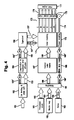
- Fig. 2 is a flow chart showing incorporation of preferred embodiments of
the invention into a Shakes masking system, e. g. such as disclosed in the earlier-mentioned
Garcia patent documents;
- Fig. 3 is a set of four views illustrating a preferred two-stage operation of
adaptive white-drop masking: in view A), a representative but exaggerated tonal
pattern of artifacts; in view B), a corresponding graph of density along the axis of the
view-A pattern, together with a representation of localized depletion applied to that
varying density as a first-stage adjustment; in view C), a tonal pattern corrected ideally
by that first-stage adjustment ― namely, a uniform field; and in view D), the same
tonal pattern after a second-stage ink-limit adjustment;
- Fig. 4 is a flow chart showing the double-branch pipeline in a preferred
embodiment of the eraser-plane form of the invention;
- Fig. 5 is a block diagram of a preferred embodiment of the basic white-drop-masking
form of the invention, including a print engine with scanning printheads;
- Fig. 6 is a bottom plan of a pagewide swath-height array for use instead of
one or more of the Fig. 5 scanning heads; and
- Fig. 7 is a top plan of a representative sheet of printing medium with two
swaths already printed by the Fig. 6 array, and with the array in position to print
another swath.
-
DETAILED DESCRIPTION
OF THE PREFERRED EMBODIMENTS
1. WHITE-DROP MASKING
(a) Constraints on conventional systems ―
-
Preferred embodiments of the
present invention aim at the root cause of the boundary artifacts problem: concentration
of ink coalescence at swath boundaries. If a full-color rectangle is printed,
visibly the ink dries in the center earlier than at the edges.
-
The beginning of a solution is to direct less ink to the edges ― that is, when
printing a given swath, to deposit less ink at the swath boundary, by a lesser use of the
end nozzles of the printhead. It can then be decided whether to make up for that ink
not fired.
-
Initially, the answer is yes: the end result should always be a so-called "full
mask". This means that, after all the passes, all the pixels on the printing grid have been
addressed the same number of times ― typically once, but more times if two or more
drops per pixel are defined.
-
In other words, the light work of any given nozzle is compensated by other
nozzles that also print on the same row but in a different pass. A full mask is extremely
desirable for light tones.
-
A few drops may be omitted when printing a fully-saturated area, and in fact
this is successfully implemented in the earlier-discussed depletion procedure ―
associated with the halftoning procedure. A white-banding line, however, appears if the
same is attempted on a light-colored area.
-
Since there seems to be a need for depletion only in saturated areas, it might be
supposed that the halftoning algorithm could decide where to apply this depletion. For
better or for worse, however, halftoning algorithms are totally ignorant of the printmode
parameters, not to mention where the swath boundary will occur.
-
Thus there is a need for a certain depletion, but localized at swath boundaries
and only for saturated-color areas. The sought-for algorithm must take into account
both halftoning and printmode information, so that printing masks are conveniently
depleted at the swath boundary but only if a significant amount of ink is present.
-
This would suggest designing printmasks that are halftone-dependent, but
conventional writing-systems architecture ordinarily allows only masks that tile over the
whole plot. It is difficult to think of all the implications of plot-dependent masking, in
terms of memory, CPU power and engineering.
(b) Multilayer masking and spare levels ―
-
Currently conventional printmasking,
however, does offer a narrow escape. To enable appreciation of that solution, first
this subsection describes some operational parts of the so-called "Shakes" printmasking
system.
-
That system is introduced and detailed in the previously mentioned Garcia documents.
The Shakes system is now routinely incorporated into incremental-printing data
pipelines.
-
Multilevel masks are, in a certain sense, plot-dependent ― because a different
number of mask layers is selected automatically, depending on the multibit value of
each pixel. The color value in each pixel discriminates between adjacent levels in the
printmasking structure.
-
To put it another way, the color value in each pixel discriminates among all the
available combinations of masks. The color value itself thereby invokes an appropriate
combination of masks to produce the necessary number of inkdrops for that pixel.
-
In the Shakes system, this is the situation just before printing:
- Binary masks A, B, C (not shown) have been generated
from multilayer Shakes masks (see sample tables below).
For instance, if the drop table reads "[0 1 2
4]", then mask A will specify the first drop, mask B
the second one, and mask C the third and the fourth
drops, as follows.
- If the two-bit code of a pixel is "00", no mask is
called up as the system should not print any drop.
- If the pixel code is "01", the system prints whatever
mask A specifies.
- If the code is "10", the system prints whatever is
specified in mask A and whatever is specified in mask
B (i. e., a Boolean "or" function, mask A + mask B).
- If "11", the system prints whatever is specified in
mask A plus (Boolean "or") whatever is specified in B,
plus ("or" again) whatever is specified in C (i. e.,
again in Boolean notation mask A + mask B + mask C).
-
In short, masks A, Band C are additive. Each mask
represents a number of drops to be fired ― and the
system selects the appropriate number of masks, based upon
the image contents.
-
Masks A, Band C are full masks. That is, if all the
pixels in a plot and data pipeline were "11", the same
number of drops would be fired onto all the pixels.
-
The Shakes drop-table contents and their implications
stated above are only an example. The implication of the
drop table specified, [0 1 2 4], can be summarized:
| level 00 | 0 drop |
| level 01 | 1 drop |
| level 10 | 2 drop |
| level |
| 11 | 4 drops. |
Ordinarily, however, the maximum number of drops used is
two ― particularly for printmodes of about three or
fewer passes or installments.
-
Therefore the last level "11" may be treated as a
spare level, available for special use. Exactly such a
diversion of level "11", for purposes of the present document,
is described in subsection (c) below.
-
Other uses of the Shakes notation heretofore, also by
way of example, include drop table [0 1 1 2], meaning:
| level 00 | 0 drop |
| level 01 | 1 drop |
| level 10 | 1 drop |
| level |
| 11 | 2 drops. |
-
A typical multilayer Shakes mask set for this pipeline
would be (for an eight-nozzle pen and four-pass printmode):
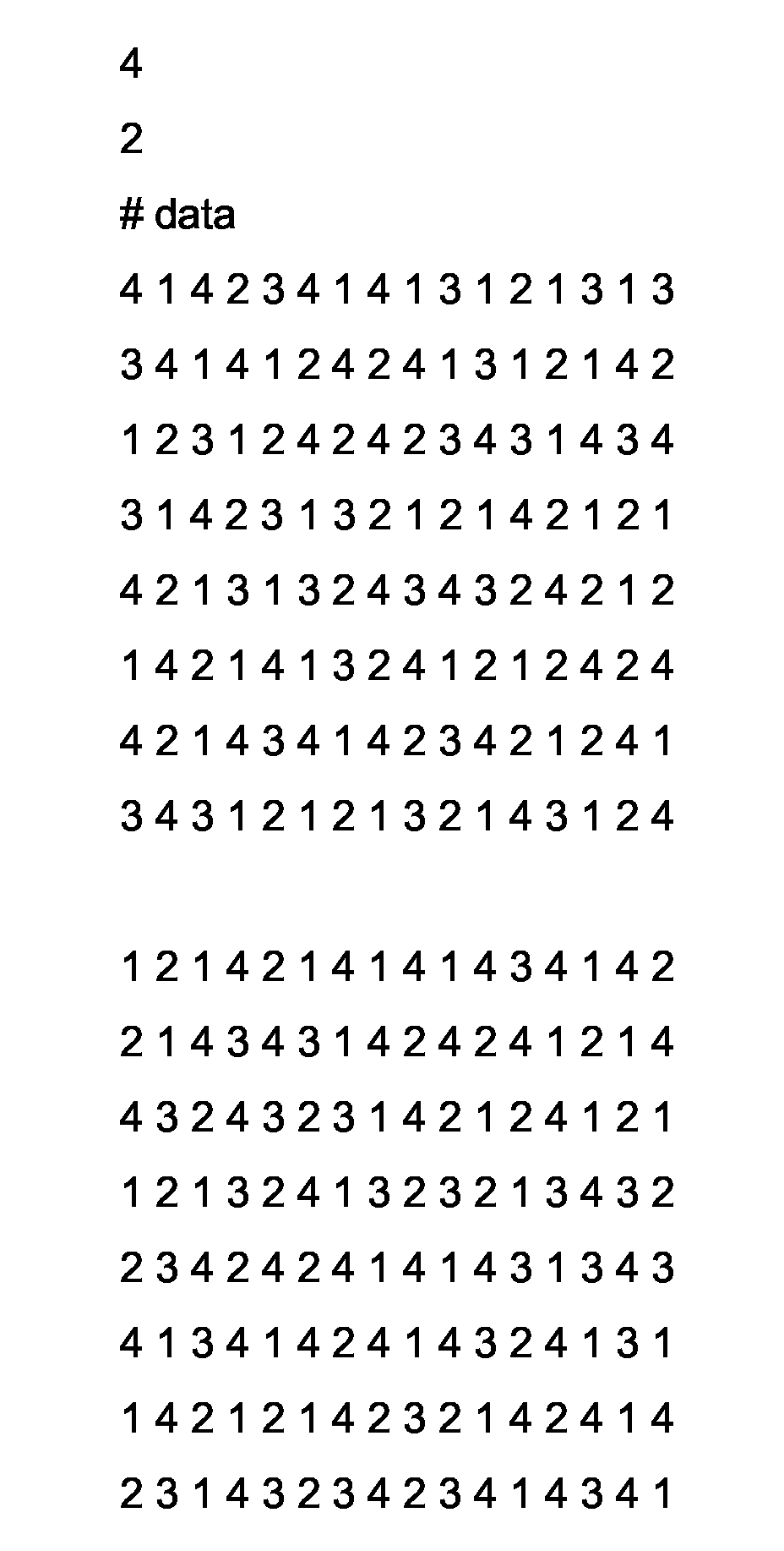
- for the first drop ―
| 4 | 1 | 4 | 2 | 3 | 4 | 1 | 4 | 1 | 3 | 1 | 2 | 1 | 3 | 1 | 3 |
| 3 | 4 | 1 | 4 | 1 | 2 | 4 | 2 | 4 | 1 | 3 | 1 | 2 | 1 | 4 | 2 |
| 1 | 2 | 3 | 1 | 2 | 4 | 2 | 4 | 2 | 3 | 4 | 3 | 1 | 4 | 3 | 4 |
| 3 | 1 | 4 | 2 | 3 | 1 | 3 | 2 | 1 | 2 | 1 | 4 | 2 | 1 | 2 | 1 |
| 4 | 2 | 1 | 3 | 1 | 3 | 2 | 4 | 3 | 4 | 3 | 2 | 4 | 2 | 1 | 2 |
| 1 | 4 | 2 | 1 | 4 | 1 | 3 | 2 | 4 | 1 | 2 | 1 | 2 | 4 | 2 | 4 |
| 4 | 2 | 1 | 4 | 3 | 4 | 1 | 4 | 2 | 3 | 4 | 2 | 1 | 2 | 4 | 1 |
| 3 | 4 | 3 | 1 | 2 | 1 | 2 | 1 | 3 | 2 | 1 | 4 | 3 | 1 | 2 | 4 |
- for the second drop ―
| 1 | 2 | 1 | 4 | 2 | 1 | 4 | 1 | 4 | 1 | 4 | 3 | 4 | 1 | 4 | 2 |
| 2 | 1 | 4 | 3 | 4 | 3 | 1 | 4 | 2 | 4 | 2 | 4 | 1 | 2 | 1 | 4 |
| 4 | 3 | 2 | 4 | 3 | 2 | 3 | 1 | 4 | 2 | 1 | 2 | 4 | 1 | 2 | 1 |
| 1 | 2 | 1 | 3 | 2 | 4 | 1 | 3 | 2 | 3 | 2 | 1 | 3 | 4 | 3 | 2 |
| 2 | 3 | 4 | 2 | 4 | 2 | 4 | 1 | 4 | 1 | 4 | 3 | 1 | 3 | 4 | 3 |
| 4 | 1 | 3 | 4 | 1 | 4 | 2 | 4 | 1 | 4 | 3 | 2 | 4 | 1 | 3 | 1 |
| 1 | 4 | 2 | 1 | 2 | 1 | 4 | 2 | 3 | 2 | 1 | 4 | 2 | 4 | 1 | 4 |
| 2 | 3 | 1 | 4 | 3 | 2 | 3 | 4 | 2 | 3 | 4 | 1 | 4 | 3 | 4 | 1 |
This means that, in the bottom-right pixel, the first drop
is to be fired in pass 4; and the second drop, pass 1. In
other words, if the pixel value is 11, a drop will be discharged
during passes 1 and 4. If the pixel value is 01
or 10, a drop is directed to this pixel location in pass 4
only. -
-
With this assignment of values, actually somewhat
preferred in some regards, levels "01" and "10" yield identical
operation. Hence either one of them may be eliminated
as an unused, spare level ― once again making room
for assignment of one level to a special purpose.
-
As a practical matter it will be understood that an
eight-nozzle pen is a thing of the past, and modern-day
pens ― and therefore masks ― typically have several
hundred or even more than a thousand nozzles. Moreover,
masks are typically some hundreds of pixels wide. The
principles under consideration, however, are independent
of absolute mask or pen size, and their discussion in
terms of an eight-nozzle pen is therefore entirely valid.
(c) Multilayer printmasking as a depletion discriminator,
with subtractive masking ―
-
Preferred embodiments
of the present invention introduce a new use of such a
spare level. In general it is preferable to rearrange the
drop-table contents if necessary so that the spare is the
highest-value level ― as it is in the first above example,
[0 1 2 4]. For instance rearrangement is necessary
if the starting configuration is considered to be the second
above example, [0 1 1 2].
-
As will shortly become more clear, such rearrangement
is desired because the previously spare level is then invoked
only in cases of maximum inking in the particular
color plane. The pixel color value itself then automatically
calls the desired special behavior as suggested in
subsection (b) above. For purposes of preferred embodiments
of the present invention, that special behavior is
to link the high level to a mechanism for mitigating
boundary artifacts or other kinds of image artifact.
-
The pixel color-value structure thus operates as a
discriminator, determining in turn when more and still
more ink is required ― and then, finally, when the
amount previously invoked may be too much. At least the
discriminator responds when that amount may be too much
for certain specific positions in the swath.
-
Thus the spare level is advantageously made to correspond
to a new, artifact-reducing use for, in particular,
mask C. This mask has several extraordinary attributes.
-
First, mask C does not add, but subtracts. Further,
it is not a full mask ― it shows only which drops called
by mask A or B must be disregarded (in a sense erased) for
a certain value of the print.
-
In this formulation mask C is called a "white-drop
mask". For comparison with the foregoing now-conventional
Shakes procedure with drop table [0 1 2 4], the system now
operates thus:
- Binary masks A and B have been generated out of multilayer
Shakes masks as before; and mask C, out of a
novel Shakes white-drop mask generator. For instance
if the drop table reads "[0 1 2 x]", then mask A will
specify the first drop, mask B the second one, and
mask C the "white" or subtractive virtual drops.
As to real drops, in effect the last value of
the drop table has been declared negligible. - If the two-bit code of a pixel is "00", as before the
system calls no mask and prints no drop.
- If "01", as before the system prints whatever mask A
specifies.
- If "10", as before the system prints whatever is
specified in A plus whatever is specified in B (Boolean
mask A + mask B).
- If "11", the system prints whatever is specified in
mask A plus (Boolean "or") whatever is specified in B
unless (Boolean "and not") mask C tells us otherwise:
(mask A "or" mask B) "and not" (mask C) = mask A +
mask B - mask C.
-
By default, mask C will have a value of zero, except
in some pixels close to the swath boundary. Bits are positioned
along the swath boundary in those mask-C pixels
known to be susceptible to boundary artifacts.
-
Then, by design, mask C affects only swath boundary
areas with high density of ink, without affecting low-density
ones ― in other words, just the desired areas
needing correction.
-
This white-drop masking protocol can be conceptualized
as providing a pen with white ink. The white ink is
applied when too much real ink would otherwise appear on
conflictive areas ― in this case, specifically, boundary
areas.
-
There seems to be a disadvantage, namely that the
conventional function for the last level of the drop table
has been lost. On the other hand, the system typically
can fire only as many drops per pixel as number of passes.
-
This preferred embodiment is of interest largely for
a printmode with a relatively small number of passes. As
such modes rarely fire more than two drops, the disadvantage
seldom comes into play.
(d) Graduated white-drop correction ―
-
If
preferred, white-drop masking can be provided in plural
masks. Swath boundary regions may be defined for each
pass differently than in other passes.
-
When each pass has its own respective boundary-banding
depletion mask, intensity of depletion can be varied
with precise position near the swath edge. It is not necessary
to be limited in depletion quantity to all drops or
none ― or to one drop or none. A depletion hierarchy is
readily established that echoes the known positionally
varying intensity of the banding itself.
-
Boundary artifacts themselves, as well as each other
type of artifact addressed in this document, are not
simple binary. Rather, each type appears in continuous
gradations arising from the variable degree of coalescence
or other underlying cause.
-
Thus a plural-bit pipeline is preferred to define a
white-drop mask. Normally, just as in the real-inkdrop
regime, two bits are used per pixel, providing three
nonzero levels: 01, 10 and 11.
(e) Leveraging preexisting systems ―
-
Preferred
embodiments of the invention are incorporated into the
masking pipeline in such a way as to minimize need for
hardware modification. Input data 111 (Fig. 2) are directed
to a conventional postscript rendition stage 112, in
which color signals defined in e. g. a graphics language
are used to generate corresponding color data 113 for use
in printing. These data are most typically eight bits per
pixel for each of four primary colorants cyan C, magenta
M, yellow Y and black K ― for a total of thirty-two bits
per pixel.
-
Also conventional is a Contone-to-halftone interface
("CHI") 114, whose operations include splitting the signal
for relatively dark chromatic colorants C and M to allow
more sensitive control of fine gradations, particularly in
image highlight regions. This splitting process yields
data 115 that include light cyan and magenta c, m ― now
at two bits per pixel for each of the total six colorants,
i. e. twelve bits overall. The CHI also halftones all of
the six resulting color planes.
-
The halftoned data next proceed to a writing-system
library 116, which selects and invokes configuration files
and other data ― as well as algorithms ― for an appropriate
printmasking regime. For instance data 121 from
the library may proceed to conventional masking 123, driven
by the Shakes master system 125, which ordinarily provides
a positive simple-binary mask 126 for each input
pixel value ― and for each colorant (i. e. each respective
nozzle array) in the system.
-
Alternatively data 122 from the library may proceed
to white-drop masking 124 in accordance with preferred
embodiments of the present invention, likewise driven by
the Shakes system 125. In this case the masking 127 produced
includes a positive simple-binary mask for each
input pixel value except the highest; plus a white-drop
(negative) mask for the highest value.
-
White-drop masks are autoselected in this way for
each of the six colorants independently; however, in some
embodiments the light colors are not depleted at all.
They are used primarily to avoid granularity in highlight
regions, where neither high inking nor the artifacts of
interest are usually problematic.
-
In the final output stage 128 the masks are applied
to the image data to generate firing-control signals for
individual nozzles in individual printing passes. It is
at this point that the subtractive character of the white-drop
mask comes into operation, deducting one or more bits
from one of the lower-value masks whenever the highest
pixel value appears.
-
It can now be seen that the data flow for white-drop
processing is substantially identical to that for conventional
operation, with the sole exception of the character
of the masking structure 127 provided from the masking
process 124 to the final output stage 128. Thus a major
advantage of preferred embodiments of the invention is
that departures from the conventional scheme are largely
limited to changes in drop tables, configuration files and
masks ― in other words, in very easily accessible data
formats rather than hardware and executable firmware.
-
Preferred embodiments of this boundary-banding form
of the invention are applicable in both a scanning printer
and a pagewide swath-height array. The problem of ink coalescence
at boundaries is roughly the same in both these
systems; however, adaptive artifact-correction forms of
the invention (discussed below) may be somewhat less powerful
in relation to pagewide swath arrays and the like,
because here each nozzle produces only an individual pixel,
not a row.
(f) Mask details ―
-
As explained above, it is
common for a Shakes system to have one spare level, or in
any event a level that can be declared to be a spare and
thereby diverted to purposes of preferred embodiments of
the present invention.
-
Some preferred white-drop embodiments map that spare
color-value level to a corresponding third level of masking,
which is zero by default. Bits in certain positions
of that level, however, are set to nonzero values ― and
these in turn are declared to correspond to so-called
"negative drops" .
-
Physically and literally speaking an inkdrop cannot
be negative. Real inkdrops have physical substance, which
is positive only.
-
Hence as earlier suggested the concept of negative or
virtual drops is no more than an intellectual construct;
it facilitates the manipulation of artifact correction or
mitigation, according to preferred embodiments of the
invention. In particular, a mask layer can be defined arbitrarily
for negative drops as well as for positive, and
such a layer can then be added as a correction or revision
to a real, positive drop layer. For instance:
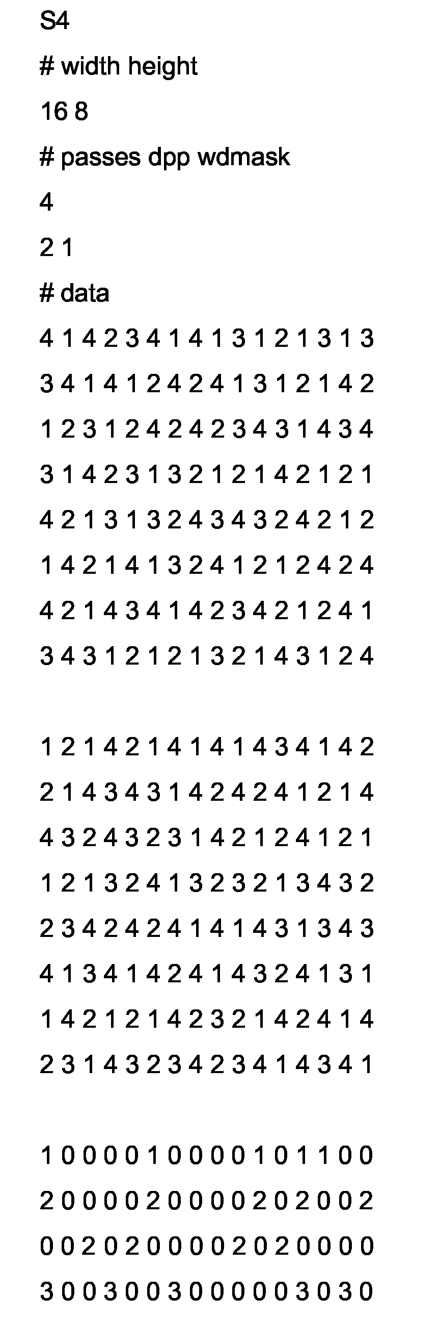
- white-drop mask ―
| 1 | 0 | 0 | 0 | 0 | 1 | 0 | 0 | 0 | 0 | 1 | 0 | 1 | 1 | 0 | 0 |
| 2 | 0 | 0 | 0 | 0 | 2 | 0 | 0 | 0 | 0 | 2 | 0 | 2 | 0 | 0 | 2 |
| 0 | 0 | 2 | 0 | 2 | 0 | 0 | 0 | 0 | 2 | 0 | 2 | 0 | 0 | 0 | 0 |
| 3 | 0 | 0 | 3 | 0 | 0 | 3 | 0 | 0 | 0 | 0 | 0 | 3 | 0 | 3 | 0 |
| 0 | 0 | 0 | 0 | 0 | 3 | 0 | 0 | 3 | 0 | 0 | 3 | 0 | 0 | 0 | 3 |
| 0 | 4 | 0 | 4 | 0 | 0 | 0 | 4 | 0 | 0 | 0 | 0 | 0 | 4 | 0 | 0 |
| 0 | 4 | 0 | 0 | 0 | 0 | 4 | 0 | 0 | 0 | 4 | 0 | 0 | 4 | 4 | 0 |
| 0 | 0 | 1 | 0 | 0 | 1 | 0 | 0 | 0 | 0 | 1 | 0 | 0 | 0 | 0 | 1 |
-
-
As this mask is considered to contain negative drops,
it can be called a "depletion mask" ― but it is separate
from the main mask (first-drop and second-drop masks).
Furthermore it is also separate from conventional depletion
masks in that, as will now be explained, it affects
the swath boundary only.
-
As with the examples taken up in subsection (b), this
example presupposes an eight-nozzle printhead, printing
four passes. The table is a so-called "shingle mask",
which by Shakes convention maps directly to a swath for
the first pass ― or, to encompass the case of a pagewide
swath-height array, the first inking installment.
-
For other installments, mask rotation or autorotation
brings different mask rows in turn to the swath boundaries
so that each swath receives boundary depletion. For pass
2 the swath boundaries are between the second and third
rows of the mask; for pass 3, between the fourth and fifth
rows; and for pass 4, the sixth and seventh. Such masking
is implemented through the conventional Shakes process of
generating from this shingle mask a corresponding number
of binary masks for application to the individual passes
respectively.
-
The shingle mask has entries "1" along the top and
bottom rows, indicating that some negative drops are to be
applied in pass 1, along those two boundaries. Thus pass
1 is depleted only in the first and last lines of the
mask, which correspond ― considered together ― to the
top and bottom swath boundary for that pass; and similarly
for the rest of the passes.
-
Even in those lines, the intention is not to deplete
the entirety of the inking ―but rather only the excess,
above nearby area-fill equivalent background, that is generated
by coalescence. Hence the "1" entries do not appear
in every pixel along either boundary, only in spaced
pixels that add up to ― in this particular example ―
some 25% to 31% of uniformly applied single-drop inking.
-
Preferably pass numbers in this mask are spaced irregularly
along their rows. Regular spacing could itself
generate repetitive patterns that would introduce moiré or
other artifacts.
-
For the sake of simplicity this reduced-size example
excludes negative drops along the left and right end boundaries.
In actual practice white-drop bits are included
there, especially if pagewide masks are in use facilitating
such placement, for printers that are particularly
susceptible to coalescence at the swath ends ― as boundary
artifacts can be quite conspicuous along the left and
right edges of the overall image. Even for narrower
masks, special left- and right-edge masks can be invoked
if the susceptibility to coalescence is severe.
-
For more-intense depletion requirements, plural-bit
white drops are also possible as mentioned above. In addition
the contour of the depletion region is not limited
to rows or columns exactly along the edge, but instead can
be made to extend two or more drops inward from the edge
of each swath. In the latter case, the average spacing
can be made progressively more sparse for pixels progressively
farther from the edge, to mirror the tendency of
coalescence to tail off progressively for regions of lower
surface tension.
-
Looking at the bottom-right pixel in the foregoing
tables
(i. e., including the two in subsection [b]), the
system behavior is now ― depending on the pixel value,
and recalling that the third mask works subtractively:
| pixel value | action |
| 00 | don't print |
| 01 | print first mask (i. e. place drop on pass 4) |
| 10 | print first and second masks (drops on pass 1, 4) |
| 11 | print first to third masks (drop on pass 4 only). |
As to the last line,
pass 1 has one drop before application
(
i. e., subtraction) of the white drop specified by
level 11, and zero drop after.
-
It could be proposed to just map
level 11 to the
first mask only, in hopes of achieving the same result ―
but this approach would not be valid. The result is different,
as the system is both position- and value-dependent.
The difference can be seen by shifting focus one
pixel to the left (still on the last row on the mask):
| pixel value | action |
| 00 | don't print |
| 01 | print first mask (i. e. place drop on pass 2) |
| 10 | print first and second masks (drops on pass 2, 4) |
| 11 | print first to third masks (drops on pass 2, 4). |
In this version, the third mask does not subtract any
drop. This example demonstrates that pixel subtraction
governed by the white-drop mask is:
- position-dependent for a given value: value 11 causes
one drop to be printed on the bottom-right
pixel, but two for its left-hand neighbor; and
- value-dependent for a given position: a certain color
may be halftoned to value 10, and get two
drops on that position, or to value 11, and get
only one drop on the same position.
-
-
Nonzero numbers in the white-drop mask correspond to
the same numbers that exist in either of the two real-drop
masks, not necessarily the first and not necessarily the
second. For instance, when value 11 must be printed in a
depletion-marked location, one drop will be fired there
instead of two ― but the subtracted drop is not
necessarily what is called "the second drop"; it is simply
that one drop is fired instead of two.
(g) Mask generation ―
-
Preferred embodiments of the
white-drop masking procedure are part of a program called
"ShakeSmall", a simplified version of Shakes developed to
run in the Hewlett Packard DesignJet 5500 printer. The
following explanation is simplified, in that it bypasses
other printmasking features (nozzle-out error hiding, and
printmask ramping) which are taken up in other patent
documents including some of those listed earlier.
-
The preferred procedure has four general steps, of
which the first two are part of Shakes and ShakeSmall:
- use rules to generate the real, positive-drop masks,
- retain those masks,
- define the rules for the white-drop mask, and
- run algorithm with those masks and rules as input.
The output for each color plane is a new mask, whose last
level corresponds to the negative drops. These steps will
be taken up in turn in the corresponding four subsections
(h) through (k) below.
(h) Generate real-drop masks ―
-
The above-depicted
masks have been created with the following script, due to
Joan-Manel Garcia.
(i) Retain masks ―
-
The result of running Shakes on
the above script yields the "positive" masks:
(j) Generate white-drop mask rules ―
-
For this
example the first and last nozzle of the swath will be
depleted by fifty percent. This fifty percent means that,
for each possible position to deplete, deciding whether to
actually deplete in a particular inking installment is
statistically equivalent to the toss of a coin.
-
As before, for this example the printhead has eight
nozzles:
- whiteRamp
nozzle: 1 value: 500 gamma: 1000
nozzle: 2 value: 0 gamma: 1000
nozzle: 7 value: 0 gamma: 1000
nozzle: 8 value: 500 gamma: 1000 - endWhiteRamp
The above syntax defines a depletion curve as a function
of the nozzle number. Rather than defining the function
for each nozzle, the protocol can define it by intervals.-
-
In the above example, values in the interval from
nozzle 2 through nozzle 7 are to be interpolated. The
parameter "gamma" sets the interpolation rules, but individually-defined
values (as for nozzles 1 and 8) override
gamma.
-
For this example the interval defined is flat; hence
all nozzles from 2 to 7 will have a value of 0 (i. e.,
they are not to be depleted). The maximum allowed value
is set to 1000, and to obtain the desired fifty-percent
depletion of nozzles 1 and 8 the value for those two nozzles
is set to 500 (500/1000 = 0.5).
-
Application of the desired fractional depletion is
only statistical. Therefore rather wide masks are needed
to achieve actual depletion very close to the desired
value, i. e. here fifty percent.
-
This "actual depletion" is, for the finished masks,
the ratio between the number of times a pass number appears
in a row, in mask 3, and the total number of times
that same pass number appears in the same row in masks 1
and 2 together. In this example, for moderate mask sizes
actual depletion values will be found in the range between
forty and sixty percent.
(k) Define and run new algorithm ―
-
This algorithm
takes as inputs the positive masks of subsection (i) and
the "whiteRamp"-script rules of subsection (j). The output
is a new mask, whose last level corresponds to the
"negative" drops:
-
So the system begins by feeding the file in subsection
(h) into a module called "Automatic Mask-Generation
algorithm" (which is the Shakes program), to output the
filing in subsection (i) ― the mask. Then subsections
(i) and (j), the white-drop definition, feed into a new
module, "White-Drop Mask Automatic Generation", and the
output is shown in this subsection (k).
-
The latter enters another new module, "Format Conversion",
that generates a binary pattern for the lower-level
masking algorithms. This binary pattern is finally combined,
in the usual manner of printmasking, with the two-bit
rasterized image ― and printed.
-
Typically, the files in (h) and (j) are kept in a
hard disc drive inside the printer, but any other kind of
nonvolatile memory can be used. Alternatively they can be
fed by the printer driver, attaching them to the header of
the file that is to be printed.
(l) Activation of white-drop masks ―
-
In the
configuration file for the master Shakes or ShakeSmall
program in the printer, a flag is to be set. It may be
called e. g. "whiteDrop 1".
-
If printmasks in use are less than full image width,
the left and right image edges usually are not treated for
boundary banding as such. Special masking for those positions
can be provided, but ordinarily this is not cost
effective.
-
For the top and bottom edges of each swath, within
ShakeSmall white-drop masking can be established in the
form of an end-of-nozzle ramp function. A function is
defined for each printhead in turn, the sequence being
CMYKcm:
- whiteRamp
nozzle: 1 value: 0 gamma: 1000
nozzle: 502 value: 0 gamma: 1000
nozzle: 503 value: 500 gamma: 1000
nozzle: 504 value: 0 gamma: 1000 - endWhiteRamp
- whiteRamp
nozzle: 1 value: 0 gamma: 1000
nozzle: 502 value: 0 gamma: 1000
nozzle: 503 value: 500 gamma: 1000
nozzle: 504 value: 0 gamma: 1000 - endWhiteRamp
- whiteRamp
nozzle: 1 value: 0 gamma: 1000
nozzle: 502 value: 0 gamma: 1000
nozzle: 503 value: 1000 gamma: 1000
nozzle: 504 value: 0 gamma: 1000 - endWhiteRamp
- whiteRamp
nozzle: 1 value: 500 gamma: 1000
nozzle: 2 value: 0 gamma: 1000
nozzle: 335 value: 0 gamma: 1000
nozzle: 336 value: 200 gamma: 1000
nozzle: 337 value: 0 gamma: 1000
nozzle: 503 value: 0 gamma: 1000
nozzle: 504 value: 1000 gamma: 1000 - endWhiteRamp
- whiteRamp
nozzle: 1 value: 0 gamma: 1000
nozzle: 502 value: 0 gamma: 1000
nozzle: 503 value: 500 gamma: 1000
nozzle: 504 value: 0 gamma: 1000 - endWhiteRamp
- whiteRamp
nozzle: 1 value: 0 gamma: 1000
nozzle: 502 value: 0 gamma: 1000
nozzle: 503 value: 500 gamma: 1000
nozzle: 504 value: 0 gamma: 1000 - endWhiteRamp
These values apply for a particular combination of printing
medium, ink and printmode ― and vary with each of
these parameters.-
-
One preferred arrangement is a three-pass mode,
printing with only 504 nozzles of a total 600. Typically
the next-to-last nozzle is depleted, so that the ink in
the last row can expand a bit more uniformly to the top
(where the depleted row is) and to the bottom (which is
dry).
-
That next-to-last row is usually half-depleted for
the C, M, c, and m pens, and fully depleted for Y. A
more-complex rule is adopted for the K head: half and
full depletion for the top and bottom respectively. Also
depleted is one of the intermediate rows that happens to
fall onto the swath boundary of the previous pass: for
total nozzle complement of 504 and printing-medium advance
of 168 rows, it is nozzle 504 - 168 = 336.
-
In most-effective practice of the invention, all the
settings are advantageously found on a trial-and-error
basis for each particular environment and combination of
medium, ink and printmode. Accordingly no definite explanation
or firm theory can be stated in terms of ink-to-media
behavior.
2. ADAPTIVE ARTIFACT COMPENSATION
(a) White-drop methods for other artifacts ―
-
White-drop masking, though initially developed to combat
boundary artifacts, has been found to be extremely
powerful beyond the removal of those particular artifacts.
-
The overall objective is not only to increase print
quality in fast, low-pass-number printmodes by reducing
boundary artifacts but also to reduce other horizontal
banding and other artifacts.
-
Such other banding arises in at least the two ways
outlined in the "BACKGROUND" section of this document,
namely printhead nozzle misdirections in the paper axis
and swath-height errors (SHE or SWE). These artifacts too
are effectively reduced through use of a compensation algorithm
based on white-drop mask generation.
-
As noted earlier, these are not intrinsically localized
with respect to all swaths ― for example, not a
priori in a coalescence-defined strip along each boundary
― as in the case of boundary artifacts. Once
established, however, as they derive from phenomena
associated with specific nozzles they are generally repetitive
in location with respect to a swath.
-
Similarly the intensity of each such artifact is not
known a priori. It is, however, often generally repetitive
over at least short times such as days or weeks.
(b) Adaptive white-drop correction ―
-
Accordingly
for these artifacts, as compared with boundary artifacts,
a principal point of departure is that an exact artifact
profile of intensity vs. location must first be discovered,
for each set of printheads in each printer, before
the artifacts can be corrected. Swath banding occurs in a
statistical pattern that depends mostly on heater firing
error, nozzle occlusion or misdirection, machine advance
error and ink-media effects (coalescence).
-
These causative factors as such need not be known;
only the present pattern is required. It can be readily
determined by preexisting calibration equipment and procedures
in at least high-end inkjet printers. Various alternative
techniques for making such determinations are
introduced in several of the earlier-listed related patent
documents, including e. g. to various degrees those of Baker,
Bockman, Borrell (serial '858), Soler and Subirada.
-
Two such procedures, for example, measure pen health
and printing-medium advance errors; these protocols are
easily invoked, and their measurement results straightforwardly
redirected to control of white-drop mask generation.
The overall procedure is adaptive in the sense that
it adapts printer operation to any current, arbitrary set
of artifact profiles ― including boundary artifacts, so
that ordinarily only the adaptive system need be operated.
-
Preferred embodiments thus include obtaining information
about current banding patterns ― or if desired a
simulation of the human perception of those patterns ―
and then, based on this information, controlling the generation
of printing masks.
-
The measurement and control loop can be operated at
the beginning of each plot, or each group of plots of a
different type from a preceding group, or each day or
week, etc. ― all depending upon the user's preferred
tradeoff between convenience and overall quality. As noted
above, most typically the machine conditions giving
rise to these types of banding are relatively stable over
periods of days and weeks; however, if machines are used
for hardcopies to be sold at professional prices ― or in
any event if fine-art results are expected ― recalibration
on a per-plot basis is probably justified.
-
With this information, the mask generator is able to
produce different white-drop masks for each pen, adjusting
the blank generation to the status of the pens and the cumulative
banding of the print mode. In other words, the
white-drop mask is adapted to the pen-to-pen, machine-to-machine
and printmode-to-printmode variability.
-
As to swath-height error, the effects of the previously
discussed variability between swath height and
print-medium advance are detected and measured by the calibration
process of the machine, for passage to the mask
generator. The result is to withdraw more ink (Fig. 1B)
or less ink (Fig. 1C) from the horizontal region, depending
on the case. Analogous correction occurs for internal
area-fill nonuniformity.
-
This approach avoids restrictions on operating modes,
and avoids time-consuming calibrations. It is necessary
only to scan one patch for each combination of colorant
and paper advance. The mask-generation procedures of section
1 above are readily adapted to this case ― the primary
difference being that the desired depletion profile
is found dynamically from the measurements rather than
specified based upon boundary-banding observations at the
factory or in development.
(c) Two-stage correction ―
-
Preferred embodiments
of the invention compensate banding for each pen
individually, through use of white-drop masks that can remove
ink from dark striations 142 (Fig. 3A) and medium-dark
striations 143 produced in a swath 140 by each colorant
independently. Thus preferred embodiments of the
present invention eliminate the previously discussed need
to find a very delicate compromise among requirements of
all the different pens.
-
The combination of all area-fill nonuniformities induces
sensitive changes from the optical-density average,
along the advance axis. When measured, these are usually
found to be highly correlated to certain discrete low and
high spatial-frequency bands.
-
Preferred embodiments of the invention measure these
ink density variations and from them determine an optimum
white-drop mask 144 (Fig. 3B) to compensate them. Again,
this compensation is performed for each pen separately,
not as a compromise.
-
This process produces a uniform area-fill profile
140" (Fig. 3C) at an ink density that is lower than nominal
(some ink has been removed). Hence, in order to
preserve the original color depth, in a second step 145
the ink limit is increased in proportion to (typically) an
average of the withdrawn ink.
-
If the input (Fig. 3A) was a uniform area fill, the
final result is a banding-corrected area fill 140"' (Fig.
3D). If the input was instead a desired image, the output
is a banding-corrected version of that image, with the
same two- stage corrections 144, 145 applied proportionally
throughout.
(d) Signed correction ―
-
In another mode of use,
banding is compensated through application of a signed
adjustment ― i. e. either negative or positive as appropriate
to counter the algebraic sign of the banding error.
Although this approach can deal with negative as well as
positive banding, and may seem more direct, and also
avoids the need for the second step just mentioned, it too
has limitations.
-
A relatively simple one is the need to carry at least
one additional bit to maintain the sign for each mask layer.
One advantageous way of doing this is to add, for
each operative mask layer, one additional mask layer for
the sign. Each color-bit adjustment layer is then operated
in accordance with the associated sign layer.
-
A more serious limitation is that for light striations
it can no longer be assumed that high colorimetric
values in the image ― automatically selecting
corresponding high mask layers ― identify the locations
where color adjustment is required. Hence the automatic
scaling of quantity of ink removal or addition to
underlying image intensity is absent.
-
As the assumed correlation with coalescence in heavy
color-saturation regions no longer holds in such cases,
inking must be adjusted independently of colorimetric saturation.
Ink may therefore sometimes be removed or added
in highlight regions of an image.
(e) Comparison with conventional depletion and propletion
―
-
The Borrell patent document mentions using the
printmasking function to divide up propletion as between
passes ― or alternatively to put all his propletion
drops in a separate pass from the conventional drops. He
does not, however, use the printmasking function to define
where (in which pixels) to position propletion drops.
-
In his system, that is determined by only the color
values represented in the basic image file. In this
regard his system is analogous to the earlier and more
broadly used depletion functions: both localize based on
image data alone.
-
Preferred embodiments of the present invention, to
the contrary, use one or more printmasks as inking-adjustment-defining
masks. Inserted bits do define exactly
where and how much depletion or augmentation is to be
applied, not merely in which pass. These embodiments
exploit the very extensive programming and storage infrastructure
established mainly for printmasking.
-
In some cases, the pattern of bits is positioned in
those masks at the factory. This corrective pattern reflects
foreknowledge of boundary-banding patterns and
magnitudes.
-
In other cases a current pattern of artifacts and
their magnitudes is instead acquired in the field by
printing and scanning a test plot ― through any of the
several techniques discussed in related patent documents
as mentioned earlier ― and then inverted to obtain the
corrective pattern. This correction pattern, as in the
case described in the preceding paragraph, is then inserted
into a mask or masks.
3. COMPOSITE-COLOR WHITE-DROP AND ADAPTIVE MASKING
(a) Limitations of the white-drop technique ―
-
As
pointed out in the "BACKGROUND" section, boundary artifacts
associated with composite colors heretofore are even more
difficult to remove than such artifacts associated with a
single primary colorant. More specifically, as can now be
appreciated, the white-drop masking and adaptive
corrections as described in the foregoing two subsections
cannot respond to composite colors as such.
-
They can respond only to high levels of inking specified
in each one of the colorants considered separately,
independently of the others. As the white-drop mask is
activated through the multibit value of each pixel in a
single color plane, it depends on the plane-specific output
value of the multilevel error diffusion algorithm ―
and thus affects only swath boundary areas with high density
of ink from a single pen.
-
White-drop masking as outlined above is excellent in
negating boundary artifacts and other artifacts that
happen to be visible in a single subtractive primary ―
and this is very common, accounting for a sizable fraction
of the artifact occurrences. Composite colors, however,
can be heavily inked in the aggregate without high saturation
in any single primary.
-
In short, high-value color signals can speak to the
white-drop masking system exclusively through just one
color-signal channel at a time. In this case, as no single
color channel has a high color signal, the high-saturation
composite color has no way to talk to the white-drop
masking system.
-
Consider the worst case, in which each pen in an N-pen-system
contributes a single drop to the same pixel.
Ordinarily one drop is not considered to cause enough coalescence
to produce boundary artifacts. Therefore, for
this particular highly saturated case (a total of N drops
has been deposited) no depletion will occur with the current
white-drop mask.
-
White-drop masking can properly correct boundary artifacts,
and the other artifacts, in composite-color areas
only when at least one channel has a high signal ― not
in general. Accordingly such masking still leaves the
artifacts uncured in a significant fraction of
occurrences.
-
A further limitation of the methods and systems just
detailed is that the last level of the drop table is lost
for a binary mask definition, as that level is diverted to
service as a placeholder for the white drop mask. Though
rarely more than two drops are fired in low-pass printmodes,
in some cases this restriction may become critical.
(b) New color plane, rather than mask layer ―
-
Other preferred embodiments of the invention, however, do
provide swath-localized ink depletion as a function of
total ink amount deposited in a region ― i. e., not only
for the primary colors as achieved with white-drop masking
but also for composite colors. These embodiments thus extend
the benefits of white-drop masking into the composite-color
regime, which is to say a sizable fraction of
the printer gamut.
-
The data pipeline in an incremental printer is a parallel
process. On one side 151-157 (Fig. 4) for example,
the image to be printed is preprocessed; and on the other
161-169 the printmasks are prepared for the specific
printing time, taking into account the nozzle health of
each pen.
-
The two paths converge in a final color-masking module
171 that applies the masks 169 to the data 157. Carried
along in parallel with the real color data and masks
in all this processing, for purposes of preferred embodiments
of the invention, are the "eraser" or "white-drop"
functions:
-
These are, in the imaging subpipe, the eraser plane
153', 155', 157'; and in the masking subpipe, the white-drop
mask 168, the eraser masking 172, and its application 174,
175 to the real color data. Preferably the eraser plane
contains data derived from total inking, i. e. from
consideration of all the real color planes as an aggregation
(rather than for each plane individually). Therefore
the eraser plane preferably responds to high inking in
composite colors.
-
Apart from those eraser/white-drop functions, the
system is substantially conventional: in the imaging
subpipeline, typically four planes of image data 151 pass
through the ink limiting and plane split processes 152,
and then proceed 153 as six planes of data (plus the eraser
plane), to the linearization and multilevel error diffusion
unit 154. All these data undergo superpixeling 156
and then proceed 157 to the color data masking block 171.
-
Meanwhile in the masking subpipe, a so-called "precooked
mask" 161 is held in nonvolatile memory ― as set
forth in the earlier-mentioned Garcia documents, particularly
the '556 patent. A current nozzle map 162 has been
acquired defining the state of health of each nozzle in
the machine, and is combined with the precooked mask 161
and a color ramp 163 in a so-called "reheating" process
165.
-
The resulting so-called "cooked color masks" 167 are
just as taught for the Shakes system and precooked masking
in the earlier documents ― except for inclusion of the
white-drop mask 168. All seven masks are passed 169, 169'
to the color data masking stage 171, to meet the image data
157 from the halftoning subpipe 151-157.
-
At that particular stage the white-drop mask 168 is
convolved with the eraser plane in an integrated eraser-masking
function 172. It is at precisely this point that
the system becomes capable of identifying high inking in
swath-localized artifact regions. Furthermore, because
the eraser plane responds to composite colors, the system
at this convergence point becomes capable of identifying
high composite-color inking in swath-localized artifact
regions.
-
In preferred embodiments, the color-masking stage
proper 172 and six real colorant data planes 173 analogously
depart from the conventional at the point of their
application 176 to the print engine 177. At that stage,
again in preferred embodiments, the innovation includes
the presence of the previously mentioned eraser-mask subtraction
stage 175.
-
As the foregoing basic white-drop details (sections 1
and 2 above) illustrate, an algorithm for localized banding
suppression can take into account both the halftoning
and the printmode information ― so that printmasks are
depleted at swath boundaries only if a high inking level
is present. The image pipeline considered alone is totally
ignorant of the printmode parameters: it has no
access to information about where swath boundaries will
occur; and conversely, the printmask system is ignorant of
inking for a particular image.
-
Preferred embodiments of basic white-drop masking
adopt a breakthrough philosophy, namely coordination of
information from the two parallel processes to enable
localized depletion. For preferred embodiments of a
composite-color extension as set forth in this section 3,
that basic white-drop philosophy of printmask manipulation
based upon inking levels is retained ―but applied at a
different tier in the pipeline.
-
Whereas basic white-drop details presented earlier
(section 1 and 2) focus on availability of a seldom-used
mask layer, preferred embodiments of the composite-color
extension abandon that formulation in favor of a wholly
new, artificial dimensionality in the machine color space.
One or more additional eraser color planes are introduced
153', 164, 166' into both the imaging and masking branches
of the pipeline, together with the typically six planes of
real color and masking data ― basically providing
bookkeeping pages in which to do the necessary accounting.
-
The added plane or planes ― rather than defining
(as do the conventional planes) what color is desired or
what ink must be provided to implement that color ―
instead define where and how much ink is to be withdrawn.
This definition is formulated depending on both the swath
positioning, known to the printmasking system; and the
information about the total ink amount that is otherwise
specified for a given position, known to the halftoning
system. Often the latter information is already available
within an ink-limiting (depletion) algorithm, which is a
part of the halftoning modules.
-
The point at which the eraser plane is introduced
into the pipeline is subject to competing considerations.
As with conventional color planes, data in the eraser
plane or planes pass through all processing stages downstream
from the eraser-plane introduction point to the
printing entry ― in both branches of the pipe. Consequently,
designing the introduction point to occur relatively
far upstream increases the computational load on
the system.
-
In the data pipelines of Hewlett Packard products,
computational burden after the printing-entry point 171,
172 (Fig. 4) is independent of the introduction-point selection
― because after printing entry each plane is
masked independently anyway.
-
Parallel to the eraser-plane introduction in the image
subpipe, as described above, an "eraser mask" (white-drop
mask) is introduced 164, 168 in the masking subpipe.
In a general way this introduction point is coordinated
with that of the eraser plane, and computational burden on
the masking side generally tracks the selection of introduction
point in the image side; however, as a general
rule the total computation in masking is a very small
fraction of that in image rendering.
-
Each candidate introduction point offers a different
compromise between processing time and memory management:
- Before 153 multilevel error-diffusion 154 ―
Introduction of the "eraser plane" at this level
is computationally less efficient, but offers a better
antipatterning robustness as the eraser-plane
data experience the error-diffusion process.
- After superpixeling and before printing ―
This option (not shown) is computationally more
efficient, because data in the new plane pass through
little or no further processing before printing; however,
it might be less stable with regard to patterning
as the previous one.
Just before printing, preferred embodiments of this form
of the invention have the six masked color planes 173 supplied
conventionally, plus at least one additional masked
eraser plane 174 that describes how much total ink to
withdraw at a given, printmode-dependent position.
(c) Subtractive application ―
-
At the end of the
pipeline, after the localized depletion profiles have been
defined as described above, the eraser plane 174 is subtracted
175 from the real color planes 173. That is, the
data sent to the printheads will not be those in the
masked color planes 173, but rather those minus the masked
eraser plane 174.
-
The eraser data, like the white-drop mask data discussed
earlier, are not necessarily simple binary. They
may instead be multilevel data, in keeping with the potential
desirability of graduated depletion ― all in accordance
with the character of the adaptive-correction measurement
results.
-
In this way, final data are generated dynamically
taking into account both position within a swath and the
total ink amount at that position. A favorable choice of
introduction point, for inserting the eraser plane into
the imaging and masking pipelines, is within the plane-split
and ink-limiting process 152.
(d) Overview ―
-
At the expense of some additional
processing time or memory usage, or both, preferred embodiments
of this form of the invention provide advantages
over the basic white-drop implementation detailed earlier.
The most important advantage is extension of white-drop
technique to composite colors. The basic ink-level-dependent,
swath-localized depletion can now be achieved
readily for composite colors as well as primaries.
-
Another advantage is introduction of a more flexible,
algorithmic ink-level dependence that is no longer tied to
the linearization thresholds of the multilevel error diffusion
process, and is therefore resolution independent.
Yet another is the extension or even replacement of conventional
depletion procedures.
-
Still another is preservation of the last level of
the drop table for conventional use. That level can be
returned to its native function of resolving highly saturated
colorimetric levels.
-
Further, preferred embodiments of this form of the
invention enable a reduced requirement of processing just
one white-drop mask, rather than one for each color. As
suggested earlier, plural eraser planes and plural white-drop
masks are within the scope of the invention ― and
in fact may be useful for artifacts of particular
chromatic character ―but are not necessary in
fundamental practice of the composite-color extension.
(e) Masking details ―
-
A multibit pipeline is
needed to define a white-drop mask. Normally, two bits
are used per pixel, which gives us three nonzero levels:
01, 10 and 11. These three levels are mapped to one or
two drops before entering the color masking module.
The previous mapping was:
| level 01 | 1 drop |
| level 10 | 1 drop |
| level |
| 11 | 2 drops. |
This yields an input of the color-masking algorithm in
drops per pixel for a real "color" plane (CLRMAT). For
example, now assuming a pen of only three nozzles and this
arbitrary pattern of bits for a sample image, the color
plane can be:
| 1 | 1 | 1 | 2 | 0 | 2 |
| 0 | 1 | 0 | 1 | 1 | 0 |
| 1 | 1 | 2 | 0 | 0 | 1 |
Using a simple checkerboard mask in a two-pass printmode
to illustrate the example:
- for the first drop (CLRMSK) ―
| 1 | 2 | 1 | 2 | 1 | 2 |
| 2 | 1 | 2 | 1 | 2 | 1 |
| 1 | 2 | 1 | 2 | 1 | 2; |
- for the second drop (complementary to the first drop
mask) ―
| 2 | 1 | 2 | 1 | 2 | 1 |
| 1 | 2 | 1 | 2 | 1 | 2 |
| 2 | 1 | 2 | 1 | 2 | 1. |
When sent to the printer pens in binary form, the foregoing
sample image masked by these masks produces these
inkings:
- for the first pass ―
| 1 | 0 | 1 | 1 | 0 | 1 |
| 0 | 1 | 0 | 1 | 0 | 0 |
| 1 | 0 | 1 | 0 | 0 | 0; |
- for the second pass ―
| 0 | 1 | 0 | 1 | 0 | 1 |
| 1 | 0 | 0 | 0 | 1 | 0 |
| 0 | 1 | 1 | 0 | 0 | 1. |
This means that, in the bottom-right pixel, the first drop
is going to be fired on pass 2, and the second one on pass
1. As the amount of drops to be fired is one, however, a
drop is deposited at this pixel location in pass 1 only.
At the top-right pixel, where the drop value is two, a
drop is deposited in both passes 1 and 2.-
-
Now, preferred embodiments of the white-drop expansion
for composite colors introduce an additional eraser
plane, which is built with a certain functional dependence
from the normal color planes. One very straightforward
function is the normalized sum of the Contone values v of
the several color planes, (v C + v M + v Y + v K + v LM + v LC)/6;
however, any dependence appears to be possible if the final
result is in effect normalized to the value range of
the Contone planes.
-
Once introduced, as pointed out earlier the eraser
plane undergoes the same processing as the real color
planes: linearization, multilevel error diffusion (halftoning),
and superpixeling. The final result is a matrix
containing the number of negative drops that are actually
to be subtracted at each pixel.
-
Following is an example of an eraser plane ― not
the white-drop mask or the final depletion matrix, but
rather only the eraser plane that establishes heavy-inking
locations. Although arbitrary, this example could in
principle be associated with the sample single color plane
shown above. The sample eraser plane shown here is the
input of the color-masking algorithm in drops per pixel:
- eraser plane (EPMAT) ―
| 1 | 0 | 1 | 1 | 0 | 2 |
| 0 | 1 | 0 | 2 | 1 | 0 |
| 0 | 1 | 1 | 0 | 0 | 0. |
-
-
From the printmode path of the pipeline a white-drop
mask is created for the eraser plane. Although this mask
could also be a multilevel one, for linear subtraction a
binary mask with only one plane is required that defines
the swath region from which ink is to be depleted. Here
is an example of such a mask:
- white mask (WDMSK) ―
| 1 | 1 | 1 | 1 | 1 | 1 |
| 1 | 0 | 1 | 0 | 1 | 0 |
| 0 | 0 | 0 | 0 | 0 | 0. |
This binary white-drop mask (WDMSK) is multiplied by the
eraser-plane matrix (EPMAT), and the product subtracted
from the real color plane matrix (CLRMAT):
-
-
The eraser-plane matrix holds information about the
number of drops that could be deleted; and the binary-white-drop
mask, information about positions at which to
delete them. The previous result is then sent to the
printer masked with the real color plane mask (CLRMSK),
which yields (CLRMAT - WDMSK*EPMAT)*CLRMSK:
- for the first pass ―
| 0 | 0 | 0 | 0 | 0 | 0 |
| 0 | 1 | 0 | 1 | 0 | 0 |
| 1 | 0 | 1 | 0 | 0 | 0; |
- for the second pass ―
| 0 | 1 | 0 | 1 | 0 | 0 |
| 0 | 0 | 0 | 0 | 0 | 0 |
| 0 | 1 | 1 | 0 | 0 | 1. |
This is only one preference for the functionality of plane
subtraction. Others can be considered.-
-
If the white-drop mask is not simple binary but instead
a multilevel mask like that for a real color plane,
a different arithmetic can be defined to offset the planes
from each other, e. g. (CLRMAT*CLRMSK - WDMSK*EPMAT). The
result (whether desired or undesired) of this approach is
to delete drops depending on the pass in which they are
fired.
-
For example one drop can be deposited in the first or
second pass, and erased from the first or second pass respectively.
Observing the arithmetic just stated, masking
will not operate if formulated to violate this rule ―
e. g. to erase in the second pass a drop deposited in the
first, or vice versa.
-
Such a drop will finally be deposited, not erased.
Interestingly, this behavior does not fully meet the initial
inventive intent; however, it does allow potentially
useful plane-dependent combinations between the masks.
-
If the white-drop mask is a multilevel mask and an
objective is to assure that a drop will always be deleted
when deletion is specified ― independently of the pass
in which it is fired ― then the white-drop mask must be
dependent on the real color mask. As there are different
real color masks, this implies that for this purpose a
white-drop mask should be associated with each real color
mask; this technique does work, though at the cost of
additional memory overhead.
4. HARDWARE FOR PREFERRED BASIC WHITE-DROP MASKING
-
Subsection 3(b) above describes processing hardware
for preferred embodiments of the eraser-plane form of the
invention. That section does not take up print-engine
details, which are substantially the same as described in
this section for preferred embodiments of basic white-drop
masking.
-
As preferred embodiments of the invention are amenable
to implementation in, or as, any one of a very great
number of different printer models of many different
manufacturers, little purpose would be served by illustrating
a representative such printer. If of interest,
however, such a printer and some of its prominent operating
subsystems can be seen illustrated in several other
patent documents of the assignee, Hewlett Packard ― such
as for example the previously mentioned document of Antoni
Gil Miquel, which particularly illustrates a large-format
printer-plotter model.
-
In some such representative printers, a cylindrical
platen 41 (Fig. 5) ― driven by a motor 42, worm and worm
gear (not shown) under control of signals from a digital
electronic processor 71 ― rotates to drive sheets or
lengths of printing medium 4A in a medium-advance direction.
Print medium 4A is thereby drawn out of a supply of
the medium and past the marking components that will now
be described.
-
A pen-holding carriage assembly 20 carries several
pens, as illustrated, back and forth across the printing
medium, along a scanning track ― perpendicular to the
medium-advance direction ― while the pens eject ink.
For simplicity's sake, only four pens are illustrated;
however, as is well known a printer may have six pens or
more, to hold different colors ― or different dilutions
of the same colors as in the more-familiar four pens. The
medium 4A thus receives inkdrops for formation of a desired
image.
-
A very finely graduated encoder strip 33, 36 is extended
taut along the scanning path of the carriage assembly
20 and read by a very small automatic optoelectronic
sensor 37 to provide position and speed information 37B
for one or more microprocessors 71 that control the operations
of the printer. One advantageous location for the
encoder strip, shown in earlier coowned patent documents
of the assignee, is immediately behind the pens.
-
A currently preferred position for the encoder strip
33, 36, however, is near the rear of the pen carriage ―
remote from the space into which a user's hands are inserted
for servicing of the pen refill cartridges. For
either position, the sensor 37 is disposed with its optical
beam passing through orifices or transparent portions
of a scale formed in the strip.
-
The pen-carriage assembly 20, 20' is driven in reciprocation
by a motor 31 ― along dual support and guide
rails (not shown) ― through the intermediary of a drive
belt 35. The motor 31 is under the control of signals
from the processor or processors 71.
-
Preferably the system includes at least four pens
holding ink of, respectively, at least four different colors.
Most typically the inks include yellow Y, then cyan
C, magenta M and black K ― in that order from left to
right as seen by the operator.
-
As a practical matter, chromatic-color and black pens
may be in a single printer, either in a common carriage or
plural carriages. Also included in the pen-carriage
assembly 20, 20' is a tray carrying various electronics.
-
Preferred embodiments of the invention are not limited
to practice with a scanning-pen system. They may instead
use a pagewide swath-height array 92 (Fig. 6), with
many nozzles 91. The printing medium 4A and the array 92
can undergo relative motion.
-
For instance the pagewide array ordinarily is successively
displaced in an advance direction 42' by a printing-medium
advance system ― or the array may be moved in
an opposite direction over the medium. Such a system can
be closely analogous to that shown in the print-engine
section of Fig. 5.
-
In this way the pagewide array 92 (Fig. 7) can print
in a plural-installment mode that deposits overlapped
swaths 93, 94, ... , to complete the image in areas 95
not yet reached by the array 92, or in a single-installment
mode with successive swaths abutted. Furthermore it
may operate in a plural-installment mode that fires plural
times between printing-medium advances, printmasked to
avoid presence of excess liquid all on the page at once.
-
Before further discussion of details in the block
diagram (Fig. 5), a general orientation to that drawing
may be helpful. Conventional portions of the apparatus
appear as the printing stage 20 through 51, and 4A, discussed
above, and also the final output-electronics stage
78 which drives that printing stage. This final-output
stage 78 in turn is driven by a printmasking stage 75,
which allocates printing of ink marks 18, 19 as among
plural passes of the carriage and pens 20, 20' across the
medium 4A.
-
Also generally conventional is a nonvolatile memory
77, which supplies operating instructions 66 (many of
which are novel and implement preferred embodiments of the
present invention) for all the programmed elements. Four-color
image data 70, at far left in the diagram, flow as
input signals 191 into the processor 71.
-
Features particularly related to preferred embodiments
of the apparatus aspect of the invention appear in
the central region of the diagram as elements 82 through
86, and 88, though features 87 are generally conventional.
All these will be detailed below. Given the statements
of function and the diagrams presented in this document, a
programmer of ordinary skill ― if experienced in this
field ― can prepare suitable programs for operating all
the circuits.
-
Conventional features also include test-pattern control
circuitry 80. This module is used for generating
test patterns for other calibration functions and the
like, as is a data path 82 for information that results
from reading of test patterns by a small colorimeter
sensor 51, or the like, that also travels on or with the
pen carriage. The use of the sensor output signal, however,
is part of preferred embodiments of the present invention
and will be detailed shortly.
-
The pen-carriage assembly is represented separately
at 20 when traveling to the left 16 while discharging ink
18, and at 20' when traveling to the right 17 while discharging
ink 19. Both callouts 20 and 20' represent the
same pen carriage, with the same pens.
-
The previously mentioned digital processor 71 provides
control signals 20B, 20'B to fire the pens with correct
timing, coordinated with platen drive control signals
42A to the platen motor 42, and carriage drive control
signals 31A to the carriage drive motor 31. The processor
71 develops these carriage drive signals 31A based partly
upon information about the carriage speed and position
derived from the encoder signals 37B provided by the encoder
37.
-
New image data 70 are received 191 into an image-processing
stage 73 ― which includes a contrast and color
adjustment or correction module 76 ― and a rendition
module 74 using dithering or error diffusion to determine
a tone value to be printed at each pixel. Additional conventional
processing stages may be included, and the drawings
are to be interpreted as showing such other conventional
stages such as ink limiting (e. g. conventional
depletion), color-saturation enhancement (e. g. propletion)
and various other forms of signal modification in
incremental printing, whether or not now known.
-
The integrated circuits 71 may be distributive ―
being partly in the printer, partly in an associated
computer, and partly in a separately packaged raster image
processor. Alternatively the circuits may be primarily or
wholly in just one or two of such devices.
-
These circuits also may comprise a general-purpose
processor (e. g. the central processor of a general-purpose
computer) operating software such as may be held for
instance in a computer hard drive, or operating firmware
(e. g. held in a ROM 77 and for distribution 66 to other
components), or both; and may comprise application-specific
integrated circuitry. Combinations of these may be
used instead.
-
Now as to nonconventional details: data from the
scanning sensor 51 pass to a test-pattern interpretation
algorithm 83, for use in determining positions and intensities
of artifacts relative to basic swaths. These artifact
data in turn are used in a module 84 that directly
generates corrective bitmap patterns.
-
As to data taken in the field, these patterns may be
representative of artifacts other than boundary artifacts;
and the boundary artifacts patterns may be found at the
factory or in the laboratory as part of the printer design
process. Alternatively, the boundary artifact patterns
too may be determined in the field.
-
The corrective bits are stored in a mask layer 88
that is most preferably the high-level mask ―e. g. a
level "11" mask as discussed previously. This mask layer
88 is regarded as signed, i. e. as containing negative
drops so that the contents of this mask layer essentially
subtract from the contents of the two layers.
-
This single mask layer thereby becomes the heart of
the depletion-unit establishing means 86, introduced earlier.
It, together with the four-state drop table and
arithmetic implied thereby, accomplishes both the discrimination
function and the correction function.
-
The other, lower masks 87, however, are not part of
the depletion-unit establishing means at all ― they are
entirely conventional printmasks in both form and function.
As will now be startlingly clear, preferred embodiments
of basic white-drop masking accomplish a remarkably
large task with a remarkably little resource: typically
just one third of a three-level printmask.
-
This is a very elegant and powerful technique.
-
The above disclosure is intended as merely exemplary,
and not to limit the scope of the invention ― which is
to be determined by reference to the appended claims.