BACKGROUND OF THE INVENTION
The present invention is related to a multi -component
analyzing apparatus, particularly, to a mixed-refrigerant
analyzing apparatus capable of analyzing refrigerant
components contained in a mixed refrigerant in a separate
manner.
Generally speaking, so-called "fluorocarbon" is
conventionally used as refrigerants which are employed in
refrigerating apparatus (cooling machines) such as,
refrigerators and air conditioners. As to fluorocarbon, there
is an HFC series of new refrigerants in addition to a CFC series
and an HCFC series of old refrigerants. These series of
fluorocarbon own various problems as to destruction of the ozone
layer, and global warming trends in earth temperatures, so that
there are duties to collect and recycling-use the
above-described fluorocarbon. Also, such fluorocarbon which
cannot be recycling-used must be firmly destroyed.
On the other hand, the fluorocarbon of R410A, R407C, R404A,
and R507A which is typically known as the new refrigerants,
corresponds to such mixed refrigerants which are formed by
mixing several sorts of single-component fluorocarbon (R32,
R125, R134a, R143a etc.) with each other in predetermined ratios .
In addition, there is fluorocarbon R502 of the old refrigerant
as the mixed refrigerant. On the other hand, in the case that
a mixing ratio of collected fluorocarbon is not proper since
fluorocarbon is collected in an erroneous manner, if this
collected fluorocarbon is directly recycling-used, then there
is a risk that performance of refrigerating apparatuss is
deteriorated, or these refrigerating apparatuss are destroyed.
As a consequence, after fluorocarbon collecting
industries have collected fluorocarbon, the collecting
industries are required to confirm as to whether or not the
collected fluorocarbon can be recycling-used by using such a
fluorocarbon meter as described in Japanese Laid-open Patent
Application No. Hei-2-124448, and then, are required to judge
as to whether the collected fluorocarbon is recycle-used, or
destroyed. In other words, concentration of fluorocarbon must
be measured before, or after collections of the fluorocarbon
in order to prevent erroneous collections and/or erroneous uses
when the fluorocarbon is collected and recycling-used.
As means capable of measuring the above-described
fluorocarbon concentration, the NDIR method has been proposed
in, for example, the above-explained patent publication 1. In
order to perform analysis of mixed refrigerants by using this
NDIR method, such a mixed-refrigerant analyzing apparatus is
employed. In this mixed-refrigerant analyzing apparatus,
while an infrared light source is provided on one side of a cell
to which a mixed refrigerant containing a plurality of
refrigerant components is applied as sample gas, both a
plurality of bandpass filters and a plurality of detectors are
provided on the other side of this cell. The plural bandpass
filters may pass therethrough infrared light (infrared rays)
having wavelengths which are fitted to infrared absorption
spectra of the above-explained refrigerant components among
infrared light which has passed through this cell. The plural
detectors measure intensity of infrared light which has passed
through these bandpass filters.
In this case, in order that a plurality of refrigerant
components which constitute the mixed refrigerant may be
individually detected in higher precision, infrared light
transmission wavelength ranges of these bandpass filters which
are provided in correspondence with the respective refrigerant
components must be set in proper range conditions. In the
conventional mixed-refrigerant analyzing apparatus, central
wave numbers (namely, inverse numbers of wavelengths) of the
above-explained bandpass filters have been determined by mainly
considering such a wavelength band that infrared absorptions
in the respective refrigerant components are large. For
example, in the case that the single component fluorocarbon of
R143a, R125, R134a, R32, R115, R12, and R22 is analyzed, as
indicated in the below-mentioned table 1, the central wave
numbers of the respective bandpass filters have been set.
| unit: cm-1 |
| | R143a | R125 | R134a | R32 | R115 | R12 | R22 |
| central wave number | 1235 | 1215 | 1187 | 1107 | 981 | 920 | 1117 |
However, in the above-described conventional
mixed-refrigerant analyzing apparatus, as represented in the
below-mentioned table 2, measurement errors of the respective
refrigerant components are very large. More specifically, as
to the fluorocarbon of R32 and R22, measurement error thereof
are large.
| R143a | R125 | R134a | R32 | R115 | R12 | R22 |
| less than 1% | 1.5% | less than 1% | 2.6% | less than 1% | 1.5% | 3.9% |
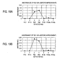
Fig. 19A and Fig. 19B indicate 100% absorbances of the
fluorocarbon R32 and R22. As apparent from these graphic
representations, such a fact can be revealed. That is, the
absorbance of the fluorocarbon R32 is influenced by the
fluorocarbon R22, and conversely, the absorbance of the
fluorocarbon R22 is influenced by the fluorocarbon R32. In
other words, these fluorocarbon R32 and R22 may have a so-called
"mutual interference relationship" by which the fluorocarbon
R32 and R22 may give interference influences to each other.
Also, Fig. 20 is a graphic diagram for representing both
infrared absorption spectra of seven refrigerant components
R143a, R125, R134a, R32, R115, R12, and R22, and also infrared
transmission characteristics of the respective bandpass
filters in a comparison manner. In this drawing, curves
indicated by symbols "A1" to "A7" show the infrared absorption
spectra of the above-described seven refrigerant components
R143a, R125, R134a, R32, R115, R12, and R22, whereas curves
denoted by symbols "B1" to "B7" represent the infrared
transmission characteristics of the bandpass filters. As
previously explained, in the conventional mixed-refrigerant
analyzing apparatus, since the central wave numbers of the
bandpass filters used to detect the respective refrigerant
components have been set to the large infrared absorptions,
namely have been set by mainly considering the low wavelength
range of the infrared absorption spectra, the central wave
numbers of the bandpass filters for the refrigerant components
R32 and R22 have been set to such positions (values) where these
central wave numbers are located in the vicinity of each other,
as indicated in the curves "B4" and "B7" in Fig. 5. As a result,
the measuring precision of these refrigerant components R32 and
R22 is mutually deteriorated.
On the other hand, the Inventors of the present invention
have filed U.S. Patent Application No. 10/207, 783 (Publication
2003-0034454-A1) by which the simultaneous equations capable
of correcting the mutual interference of the multiple
components contained in the sample gas are solved so as to
acquire the component ratios in such a similar case that a
plurality of refrigerant components contained in a mixed
refrigerant are analyzed. In such a calculation process
operation is carried out, the following setting operation may
constitute a very important aspect. That is, the infrared
transmission wavelength ranges in the bandpass filters used to
detect the refrigerant components corresponding to the
measuring-subject components are set in such a manner that the
desirable analysis results may be obtained.
In this measuring method, assuming now that a total number
of measuring-subject components is "n", the intensity of the
infrared light having the wavelength range fitted to the
infrared absorption spectra of the respective
measuring-subject components of the infrared light which has
passed through the measuring-subject sample is measured by the
non-dispersion type infrared gas analyzing meter (NDIR gas
analyzing meter) having "n" pieces of the measuring devices.
Then, in this non-dispersion type infrared gas analyzing meter,
the absorbances "y1" to "yn" are calculated based upon the
measurement values of the respective measuring devices, and
then, the analyzing operation is carried out by employing the
respective absorbances "y1" to "yn", so that the respective
concentration "x1" to "xn" can be calculated.
It should be understood that since the above-explained
absorbances "y1" to "yn" are defined as a logarithm of such a
value obtained by subtracting measurement values of the
respective detectors acquired when, for example, a
measuring-subject sample is measured from measurement values
acquired when zero gas is measured, attenuations of absorbances
occurred by mixing the respective measuring-subject components
with each other can be expressed by an addition, and thus, the
subsequent calculation process operations can be carried out
in a simple manner. As a result, since measurement values by
the respective measuring devices may be sometimes obtained as
logarithmically-calculated absorbances, it is so assumed that
measurement values acquired by the respective measuring devices
express the absorbances "y1" to "yn" in the below-mentioned
descriptions. However, the present invention is not limited
to this point.
The below-mentioned formula (1) corresponds to linear
simultaneous equations which indicates one example of
simultaneous equations employed so as to analyze the
concentration "x
1" to "x
n", and represents a summation of
one-dimensional equations corresponding to the concentration
"x
1" to "x
n" of the respective measuring-subject components.
In other words, since the linear simultaneous equations are
solved, the respective concentration "x
1" to "x
n" can be
analyzed based upon the measurement values "y
1" to "y
n" obtained
by the respective measuring devices:
It should be noted that the linear simultaneous equations are
made of "n" pieces (i=1 to "n") of simultaneous equations.
Symbol "i" shows a number of a detector, symbol "j" indicates
a number of a measuring-object component, symbols "y
1" to "y
n"
represent measurement values obtained from "n" pieces of the
detectors which detect transmission light having different
wavelength ranges from each other, symbols "x
1" to "x
n" show
concentration as to "n" pieces of components, and symbol "a
ij"
denotes a constant.
Also, in the simultaneous equations indicated in the
above-explained formula (1), in such a case that there is no
linear relationship between each of the component concentration
"x
1" to "x
n" and a dependent variable (measurement values y
1 to
y
n), and the respective component concentration x
1 to x
n cannot
be approximated to the dependent variable in a linear manner,
as represented in a formula (2), such non-linear simultaneous
equations with employment of a polynomial higher than, or equal
to a quadratic equation may be employed:
It should also be noted that symbols a
ij, b
ij, c
ij, ... show
constants, symbol "i" shows a number of a detector, and symbol
"j" represents a number of a measuring-subject component.
However, since the above-described measurement values
"'y1" to "yn" acquired by the respective detectors are obtained
in such a way that after such a infrared light having a
predetermined wavelength range has been selectively penetrated
by employing, for example, a plurality of optical filters among
the infrared light which has passed through the
measuring-subject sample, the respective detectors detect
intensity of the infrared light which has passed through the
respective optical filters, there is no way capable of avoiding
such an event that several widths are produced in the
wavelengths of the transmission light due to the filter
characteristics of the optical filters. Then, the
relationship between the filter characteristics of the optical
filters and the infrared absorption spectra of the respective
measuring-subject components may constitute an important
element capable of establishing the relationship of the
above-explained formulae (1) and (2).
However, as shown in Fig. 12, the infrared absorption
spectra of the respective measuring-subject components own the
wavelength dependent characteristics even in narrow ranges of
the respective optical filters, and is overlapped with each
other. As a result, such an adverse influence for distorting
the filter characteristics of the above-explained optical
filters is received by the infrared absorptions of other
measuring-subject components mixed with each other, so that the
absorbances which have been converted into the logarithms
cannot become completely equal to such absorbances obtained by
adding the absorbances to each other obtained by the respective
measuring-subject components. Thus, there are some
possibilities that errors caused by the interference influences
may occur in the measurement values "y1" to "yn" detected by
the respective detectors. It should be understood that in Fig.
12, symbols "Aa" to "Ag" represent infrared absorption spectra
of the respective measuring-subject components, and symbols
"Ba" to "Bg" show infrared transmittance characteristics of the
optical filters.
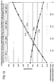
Fig. 13 is a diagram for graphically indicating
differences between calculation values of absorbances and
measurement values of the absorbances, while these calculation.
values of absorbances obtained by substituting concentration
of the respective measuring-subject components for the
multi-dimensional (three-dimensional) simultaneous equations
shown in the above-explained formula (2) when a mixing ratio
of the fluorocarbon R125 and the fluorocarbon R134a as one
example of the measuring-subject components is changed from 0%
to 100%.
In Fig. 13, symbols "C125" and "C139a" represent calculation
values of absorbances which are calculated every detector
corresponding to each or the measuring-subject components by
substituting concentration corresponding to a mixing ratio of
the fluorocarbon R125 to the fluorocarbon R134a for the
simultaneous equations . On the other hand, symbols "D125" and
"D134a" indicate measurement values detected by the respective
detectors when such a mixed gas of the fluorocarbon R125 and
the fluorocarbon R134a is actually measured. As can be
understood from Fig. 13, the largest differences between the
calculation value C125 and the measurement value D125, and between
the calculation value C134a and the measurement value D134a may
appear when both the fluorocarbon R125 and the fluorocarbon
R134a are mixed with each other in the ratio of 50 weight %.
Also, a difference between the values C125 and D125 of the
above-described absorbances is on the order of 0. 008 at maximum,
and is on the order of 2.7% with respect to the magnitude (0.30)
of the absorbance.
In other words, as shown in the above-explained formula
(2), in such a case that even when the quadratic equation, or
higher polynomial is employed, there are mutually interference
influences in the measured wavelengths of the respective
components, there are some changes in outputs due to the
component concentration which may cause the interference.
Thus, even if the simultaneous equations as indicated in the
formula (2) are solved, there are some possibilities that errors
of several % happen to occur.
However, very recently, higher precision less than 1% is
required for such multi-component analyzing apparatus capable
of calculating concentration ratios of fluorocarbon, so that
the conventional multi-component analyzing apparatus could not
be suitably used in such higher precision.
Furthermore, specifically, in such multi-component
analyzing apparatus, when a measurement is made of a standard
sample constituted by single components, and also, another
measurement is made of such a standard sample which is
constituted by mixing a plurality of measuring-subject
components with each other in predetermined concentration,
higher precision may be required. Since a plurality of these
measuring-subject components are mixed with each other in the
preselected concentration, the measuring-subject components
may mutually interfere with each other. As a result, there is
no way to avoid such a fact that errors are increased.
SUMMARY OF THE INVENTION
The present invention has been made to solve the
above-described problems, and therefore, has an object to
provide a multi-component analyzing apparatus capable of
improving calculation precision in each of component ratio
calculations, for instance, with respect to a fluorocarbon
concentration measuring apparatus which may measure component
ratios of new/old mixed refrigerants (fluorocarbon) used in
refrigerating/air conditioning machines.
Another object is to provide a mixed-refrigerant
analyzing apparatus capable of analyzing a plurality of
refrigerant components corresponding to measuring-subject
components in high precision, while mutual interference of
these plural refrigerant components may be suppressed as much
as possible.
To achieve the above-described object, a multi-component
analyzing apparatus, according to the present invention, is
featured by such a multi-component analyzing apparatus in which
infrared light is irradiated to a measuring-subject sample
which is constituted by either measuring-subject components
whose sorts or quantities are limited or by a mixed article made
of the measuring-subject components; intensity of infrared
light having respective wavelength ranges which are fitted to
infrared absorption spectra of the respective
measuring-subject components among such infrared light
penetrated through the measuring-subject sample is measured by
employing a plurality of detectors corresponding thereto; and
the multi-component analyzing apparatus is comprised of a
calculation processing unit for analyzing the infrared light
intensity of the respective wavelength ranges so as to acquire
concentration of the respective measuring-subject components;
in which the calculation processing unit is capable of executing
an analyzing process program for executing analysis operations
of the concentration of the respective measuring-subject
components by solving simultaneous equations which are
constituted by equations having mutual interference correction
terms used to correct interference adverse influences occurred
among the respective measuring-subject components.
In the above-described analyzing process program, since
the analyzing process operation is carried out by solving the
simultaneous equations which are constituted by the equations
having the mutual interference correction terms used to correct
the interference adverse influences occurred among the
respective measuring-subject components, even in such a case
that the interference adverse influences are mutually given to
each other in the measuring wavelength ranges of the respective
measuring-subject component gas, the high-precision
calculation can be carried out. Since the above-described
mutual interference correction terms are employed in the
analyzing calculation, the errors can be reduced to
approximately 0.2 to 0.3 weight %, so that the precision of the
analyzing calculation operation may be furthermore improved.
In addition, even when such interference adverse
influences such as an overlapping phenomenon are given in the
infrared absorption spectra of the respective
measuring-subject components, the calculation processing unit
analyzes the simultaneous equations having the mutual
interference correction terms, the interference adverse
influences can be firmly canceled. As a result, as to bandpass
filters mounted on the respective detectors, the half-value
widths thereof are no longer made unnecessarily narrow in order
to avoid the partially overlapping effects of the infrared
absorption spectra of the respective measuring-subject
components. In other words, it is possible to provide such a
low-cost multi-component analyzing apparatus whose
performance does not depend upon the performance of the bandpass
filters.
Also, sorts of measuring-subj ect components (namely, gas
sorts) are not limited unless the infrared absorption spectra
of the measuring-subject components are completely overlapped
with each other over the entire range of the measurement wave
numbers. In fact, with respect to any of measuring-subject
samples constituted by mixing a plurality of measuring-subject
components in which gas sorts and a total number of gas
components to be handled have been previously limited,
concentration ratios of these respective measuring-subject
components may be calculated.
In the case that the mutual interference correction term
includes a product made by multiplying a product of
concentration of at least two measuring-subject components by
one, or more mutual interference correction coefficients, since
the simultaneous equations having the mutual interference
correction term are solved, the mutual interference can be
precisely corrected. This mutual interference correction term
is made by multiplying a product of constants by the product
of the concentration of at least two measuring-subject
components.
As the simultaneous equations employed in the
above-described analyzing calculation operation, for example,
as indicated in the below-mentioned formula (3), such an idea
may be conceived. That is, a product between concentration of
a measuring-subject sample and a constant is multiplied plural
times as a term which is added to a multi-dimensional
(approximately three-dimensional) equation as a basic equation.
It should be noted that the basic equation of the present
invention is not limited only to the three-dimensional equation,
but also not limited to such an equation to which a correction
term is added:
Note that in this formula (3), symbol "i" indicates a number
of a detector, symbol "j" represents a number of a
measuring-subject component, symbol "k" represents a number of
a measuring-subject component which may interfere with a j-th
measuring-subject component, symbol "n" shows a total number
of measuring-subject components, and symbol "d
ijk" denotes a
mutual interference correction coefficient, and when j=k, this
mutual interference correction coefficient "d
ijk" is equal to
zero.
It should be noted that the above-described invention
indicates that the mutual interference correction term owns the
product of the concentration of at least two measuring-subject
components, but the present invention is not limited thereto.
In other words, in such a case that the above-described mutual
interference correction term is made by multiplying the product
of the concentration of the two measuring-subject components
by the mutual interference correction coefficient, the
calculation processing unit can perform the analyzing operation
in high precision by executing the analyzing calculation
operation with employment of necessary minimum numbers of
simultaneous equations, so that the calculation speed may be
improved while sufficiently higher precision may be realized.
Also, since the mutual interference correction term is
limited by such a product of the concentration of the two
measuring-subject components, the above-described formula (3)
may be simplified as indicated in, for example, the following
formula (4):
In the case that the mutual interference correction
coefficient is such a value obtained by dividing a difference
by the product of the concentration of the two measuring-subject
components, while the difference is calculated between a
measurement value obtained by measuring a calibration-purpose
sample formed by mixing two measuring-subject components with
each other in a preselected ratio, and such a value obtained
by substituting the concentration of the two measuring-subject
components for such equations from which the mutual
interference correction terms have been eliminated among the
equations, the mutual correction coefficient may be easily
calculated.
Also, in such a case that the equations are
multi-dimensional equations; and the analyzing process program
executes a stepwise calculation processing operation by which
the concentration of the respective measuring-subject
components is analyzed by employing simultaneous equations
which are arranged by one-dimensional equations other than the
multi-dimensional equations so as to calculate approximated
values as to the concentration of the respective
measuring-subject components, and the multi-dimensional
simultaneous equations are converged by employing the
approximated values, the calculation speed can be increased
even when the analyzing operation is carried out in high
precision.
In other words, the above-explained multiple stepwise
calculating process operation implies that such a portion that
the multi-dimensional equation of the present invention cannot
be expressed by employing the one-dimensional equation may be
compensated by the higher-order terms, while utilizing such a
fact that the coefficient of the first-order term may become
a large value capable of giving the highest influence. As a
consequence, in such a case that the non-linear simultaneous
equations are solved by using the Newton' s method which is known
as the numerical solving method of the equation, an approximated
value is obtained from the one-dimensional equation, so that
a solution may be converged in a very high speed.
In such a case that the above-explained calculation
processing unit owns a standard sample correction coefficient
which corresponds to either a ratio or a difference between
measurement values of the respective detectors obtained by that
while either standard samples made of single measuring-subject
components or standard samples formed by mixing a plurality of
measuring-subject components in predetermined concentration
is employed, the respective standard samples are measured, and
calculation values obtained by substituting the concentration
of the standard samples for the simultaneous equations, and the
standard sample correction coefficient has been stored in
relation to each of the standard samples in order to further
correct the simultaneous equations; and also the analyzing
process program executes the analyzing process operation in the
case that while the concentration of the respective
measuring-subject components acquired by the analyzing process
operation is compared with the concentration of the standard
sample, when the relevant standard sample is present, the
standard sample correction coefficient related to the relevant
standard sample is employed so as to execute the analyzing
process operation, if a one-point calibration is carried out
in the vicinity of the concentration ratio of the standard
sample, then such a precision lower than, or equal to 0.1 weight %
may be expected.
According to the second aspect of the invention, a
mixed-refrigerant analyzing apparatus employs the
below-mentioned means.
In other words, a mixed-refrigerant analyzing apparatus,
as recited in Claim 1 of the present invention, is featured by
such a mixed-refrigerant analyzing apparatus comprising: a cell
to which a mixed refrigerant containing a plurality of
refrigerant components is supplied as sample gas; an infrared
light source for irradiating infrared light to the cell; a
plurality of bandpass filters for -penetrating there through
infrared light having wavelengths which are fitted to infrared
absorption spectra of the respective refrigerant components
among infrared light which has penetrated the cell; and a
plurality of detectors for measuring intensity of the infrared
light which has penetrated the respective bandpass filters; in
which at least two bandpass filters are provided among such
bandpass filters, the infrared transmission central wave
numbers of which are set to 1222 to 1235 cm-1, 1205 to 1220 cm-1,
1180 to 1192 cm-1, 1065 to 1088 cm-1, 981 to 1000 cm-1, 908 to
933 cm-1 and 798 to 820 cm-1, respectively.
Also, a mixed-refrigerant analyzing apparatus of the
present invention is featured by such a mixed-refrigerant
analyzing apparatus comprising: a cell to which a mixed
refrigerant containing a plurality of refrigerant components
is supplied as sample gas; an infrared light source for
irradiating infrared light to the cell; a plurality of bandpass
filters for penetrating therethrough infrared light having
wavelengths which are fitted to infrared absorption spectra of
the respective refrigerant components among infrared light
which has penetrated the cell; and a plurality of detectors for
measuring intensity of the infrared light which has penetrated
the respective bandpass filters; in which at least two bandpass
filters are provided among such bandpass filters, the infrared
transmission central wave numbers of which are set to 1263 to
1269 cm-1, 1137 to 1151 cm-1, 1180 to 1192 cm-1, 1065 to 1088 cm-1,
981 to 1000 cm-1, 908 to 933 cm-1, and 798 to 820 cm-1,
respectively.
Also, a mixed-refrigerant analyzing apparatus of the
present invention is featured by such a mixed-refrigerant
analyzing apparatus comprising: a cell to which a mixed
refrigerant containing a plurality of refrigerant components
is supplied as sample gas; an infrared light source for
irradiating infrared light to the cell; a plurality of bandpass
filters for penetrating therethrough infrared light having
wavelengths which are fitted to infrared absorption spectra of
the respective refrigerant components among infrared light
which has penetrated the cell; and a plurality of detectors for
measuring intensity of the infrared light which has penetrated
the respective bandpass filters; in which at least two bandpass
filters are provided among such bandpass filters, the infrared
transmission central wave numbers of which are set to 1222 to
1235 cm-1, 1137 to 1151 cm-1, 1180 to 1192 cm-1, 1065 to 1088 cm-1,
981 to 1000 cm-1, 908 to 933 cm-1, and 798 to 820 cm-1,
respectively.
Furthermore, a mixed-refrigerant analyzing apparatus of
the present invention, is featured by such a mixed-refrigerant
analyzing apparatus comprising: a cell to which a mixed
refrigerant containing a plurality of refrigerant components
is supplied as sample gas; an infrared light source for
irradiating infrared light to the cell; a plurality of bandpass
filters for penetrating therethrough infrared light having
wavelengths which are fitted to infrared absorption spectra of
the respective refrigerant components among infrared light
which has penetrated the cell; and a plurality of detectors for
measuring intensity of the infrared light which has penetrated
the respective bandpass filters; in which at least two bandpass
filters are provided among such bandpass filters, the infrared
transmission central wave numbers of which are set to 1263 to
1269 cm-1, 1205 to 1220 cm-1, 1180 to 1192 cm-1, 1065 to 1088 cm-1,
981 to 1000 cm-1, 908 to 933 cm-1 and 798 to 820 cm-1, respectively.
In any of the above-described mixed-refrigerant
analyzing apparatus with employment of the arrangements, since
the infrared transmission wavelength ranges of the bandpass
filters used to detect the respective plural refrigerant
components are set based upon such a condition that the S/N is
increased and interference influences caused by the own
refrigerant component are not given to other refrigerant
components, this mixed-refrigerant analyzing apparatus can
analyze the respective refrigerant components of the mixed
refrigerant in higher precision while suppressing the mutual
interference caused by the plural refrigerant components as
much as possible.
BRIEF DESCRIPTION OF DRAWINGS
Fig. 1 is a diagram for indicating an entire arrangement
of a multi-component analyzing apparatus of the present
invention;
Fig. 2 is a diagram for showing an example of an inspection
apparatus for calibrating the multi-component analyzing
apparatus;
Fig. 3 is a diagram for showing a relationship between
concentration of R125 and an absorbance detected by a second
detector;
Fig. 4 is a diagram for indicating a relationship between
concentration of R134a and an absorbance detected by the second
detector;
Fig. 5 is a diagram for showing a relationship between
concentration of R125 and an absorbance detected by a third
detector;
Fig. 6 is a diagram for indicating a relationship between
concentration of R134a and an absorbance detected by the third
detector;
Fig. 7 is a diagram for indicating an example of operations
of an analyzing process program;
Fig. 8 is a diagram for indicating a display example of
an analysis result;
Fig. 9 is a diagram for indicating a display example of
an analysis result;
Fig. 10 is a diagram for indicating a display example of
an analysis result;
Fig. 11 is a diagram for confirming precision of
simultaneous equations employed in the multi-component
analyzing apparatus of the present invention;
Fig. 12 is a diagram for comparing transmittances of light
of the respective measuring-subject components and
characteristics of the respective bandpass filters;
Fig. 13 is a diagram for confirming the errors occurred
in the simultaneous equations employed in the conventional
multi-component analyzing apparatus;
Fig. 14 schematically indicates an example of an
arrangement of a mixed-refrigerant analyzing apparatus
according to the present invention;
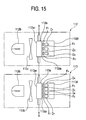
Fig. 15 schematically represents an arrangement of an
analyzing unit of the infrared gas analyzing meter;
Figs. 16A and 16B schematically show an arrangement of
a detecting unit of the infrared gas analyzing unit;
Fig. 17 is a diagram for indicating an example of infrared
transmittances and infrared transmission characteristics of
respective bandpass filters, employed in the mixed-refrigerant
analyzing apparatus;
Fig. 18 is a diagram for indicating another example of
infrared transmittances and infrared transmission
characteristics of respective bandpass filters, employed in the
mixed-refrigerant analyzing apparatus;
Figs. 19A to 19D are diagrams for explaining mutual
interference occurred in the refrigerant components R32 and
R22; Fig. 19A and Fig. 19B are diagrams for representing
absorbances of the refrigerant components R32 and R22 when the
conventional mixed-refrigerant analyzing apparatus is used;
and Fig. 19C and Fig. 19D are diagrams for representing
absorbances of the refrigerant components R32 and R22 when the
mixed-refrigerant analyzing apparatus is employed; and
Fig. 20 is a diagram for indicating the infrared
transmittances and the infrared transmission characteristics
of the respective bandpass filters, employed in the
conventional mixed-refrigerant analyzing apparatus.
DETAILED DESCRIPTION OF THE PREFERRED EMBODIMENTS
First Embodiment
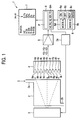
Fig. 1 is a schematic diagram for indicating an overall
arrangement of a fluorocarbon concentration measuring
apparatus functioning as an example of a multi-component
analyzing apparatus according to the present invention. In Fig.
1, reference numeral 2 indicates a measuring cell used to
conduct the fluorocarbon "S" which has been collected as one
example of a measuring subject sample, and reference numeral
3 indicates an infrared light source for irradiating infrared
light to the measuring cell 2. Also, reference numeral 4
indicates a detector for detecting transmission light of the
infrared light, which has passed through the measuring cell 2.
Reference numeral 5 shows an amplifier for amplifying a
detection output from the detector 4. Reference numeral 6
represents a calculation processing unit which executes an
analyzing process program "P" so as to perform an analyzing
operation. In accordance with this analyzing process program
P, intensity of transmission light amplified by the amplifier
5 is calculated/processed so as to acquire concentration (for
example, weight %) the respective measuring-subject components.
Reference numeral 7 shows a display unit for displaying thereon
a measurement result, and reference numeral 8 indicates a
keyboard used to enter operations by an operator.
On the keyboard 8, manual mode selecting buttons 8d and
8e are provided in addition to, for example, a power supply
ON-button 8a, a power supply OFF-button 8b, and a measuring
button 8c.
The measuring cell 2 of this example has, for instance,
a flow inlet 2a of the fluorocarbon S and a flow outlet 2b of
the fluorocarbon S . Then, in this fluorocarbon concentration
measuring apparatus 1, the fluorocarbon S which has been
collected into Bombe (not shown in this drawing) is acquired
and conducted from the flow inlet 2a into the measuring cell
2. Under such a condition that the fluorocarbon S is filled
into the measuring cell 2, concentration of this filled
fluorocarbon S is measured.
It should be understood that while such a
measuring-subject sample "S" whose concentration component is
varied moment by moment is supplied to flow through the
measuring cell 2, the multi-component analyzing apparatus 1 of
the present invention may measure concentration components of
this measuring-subject sample S in real time. In this
alternative case, the multi-component analyzing apparatus 1 may
be provided as a monitor within a fluid flowing path.
Also, while the multi-component analyzing apparatus 1 of
the present invention is combined with a flow rate meter, a
change contained in concentration of fluorocarbon which has
been collected as the measuring-subject sample S is recorded
and this recorded concentration change is integrated with a flow
rate of this collected fluorocarbon, so that the
multi-component analyzing apparatus 1 may measure a total
amount of the collected fluorocarbon. Also, in the case that
boiling points of respective single-component fluorocarbon
which constitutes collected fluorocarbon are different from
each other, even when the fluorocarbon is derived under
vaporization state, a concentration ratio of fluorocarbon
stored in Bombe may be correctly calculated.
Furthermore, since this example indicates such an example
that the measuring-subject sample S is the fluorocarbon, the
following description will be made as follows: That is, the
multi-component analyzing apparatus is employed as a
fluorocarbon concentration measuring apparatus 1, and the
measuring-subject sample is employed as fluorocarbon "S".
However, the present invention is not limited only to such a
condition that the measuring-subject sample corresponds to the
fluorocarbon S.
The above-described infrared light source 3 is, for
example, a thin-film light source, and reference numeral 3a
corresponds to a light source control unit of this thin-film
light source 3. Then, while the light source control unit 3a
supplies electric power to the thin-film light source 3 in an
intermittent manner, the thin-film light source 3 irradiates
infrared rays in the intermittent manner in connection with the
supply of electric power from the light source control unit 3a,
so that such a detector as a pyroelectric type detector may be
employed. This pyroelectric type detector produces a signal
which is directly proportional to a change of incident infrared
rays. Also, the thin-film light source 3 can be made not only
compact as well as can be operated in small power consumption,
as compared with a general-purpose infrared light source, but
also can emit the infrared rays in the interrupted manner in
combination with the above-described light source control unit
3a. As a result, a chopper having a mechanical drive unit is
no longer provided.
In other words, in the non-dispersion type infrared gas
analyzing apparatus, since the above-described arrangement is
employed, the infrared gas analyzing apparatus can be made
compact, and the manufacturing cost thereof can be reduced.
Further, warming-up operation of this infrared gas analyzing
apparatus can be eliminated, so that easy operations thereof
can be achieved, and also a content amount of the fluorocarbon
S may be measured, while an operation may have a sense of a tester.
In addition, since the mechanically operating member is omitted,
the operation of this infrared gas analyzing apparatus can be
carried out under stable condition, and also, occurrences of
malfunction thereof can be suppressed.
The detector 4 contains 9 sorts of bandpass filters "9a"
to "9i", and pyroelectric type detectors "4a" to "4i" which are
employed in correspondence with the respective bandpass filters
9a to 9i. Since the pyroelectric type detectors 4a to 4i are
employed as the detector in this embodiment mode, each of light
receiving areas of these detectors can be made very small, for
example, on the order of 0.1 to 1 mm2, and a large number of
these pyroelectric type detectors 4a to 4i and also a large
number of these bandpass filters 9a to 9i can be provided in
the array form. Seven sorts of bandpass filters 9a to 9g among
the 9 sorts of bandpass filters 9a to 9i may limit wavelengths
of infrared rays which may pass through these seven bandpass
filters to a predetermined range in order to be fitted to
infrared absorption spectra of 7 sorts of single components
contained in the fluorocarbon S.
As apparent from the foregoing description, this does not
imply that the respective single components contained in the
collected fluorocarbon S are limited only to 7 sorts of single
components in the multi-component analyzing apparatus 1 of the
present invention. Even when how many single components of
fluorocarbon are contained in the fluorocarbon S, a total number
of bandpass filters 9a to 9i and also a total number of
pyroelectric type detectors 4a to 4i may be set in accordance
with a single component number of fluorocarbon S to be handled.
The total number of these bandpass filters and pyroelectric type
detectors are equal to at least a total number of single
components contained in fluorocarbon S to be handled.
In this example, since the bandpass filters and the
pyroelectric type detectors are employed as a reference purpose
in order to correct light amount variations of the light source
by employing such a wavelength range where infrared absorptions
of the respective single components do not occur, and also are
employed so as to measure concentration of lubricating oil mixed
into refrigerants and also to perform the HC measurement for
judging as to whether or not fluorocarbon can be recycling-used,
the total number of these bandpass filters and of pyroelectric
type detectors are selected to be larger than the total number
of fluorocarbon components by 2.
In other words, the multi-component analyzing apparatus
1 of the present invention employs as the detector 4, plural
sets of bandpass filters and pyroelectric type detectors, the
total numbers of which are larger than, or equal to at least
a total number of measuring gas sorts and of realizing reference
purpose. It should be noted that since a total number of the
measuring-subject components is seven sorts in this example,
measurement values thereof may be represented as seven
variables '"YZ1" to "YZ7", "YS1", and "YS7".
Then, the above-described calculation processing unit 6
contains a storage unit "6m". This storage unit 6m stores
thereinto characteristics of the respective detectors 4a to 4i,
characteristics of the respective bandpass filters 9a to 9i,
and furthermore, respective coefficients (constants) "aij",
"bij", "cij", "dijk", "rli", "a'ij", and so on (will be explained
later). Also, since the calculation processing unit 9 executes
the analyzing process program P, this calculation processing
unit 6 executes a calculation processing operation by employing
the measurement values YZ1 to YZ7, YS1, to YS7, which are entered
from the respective detectors 4a to 4g, and also, respective
coefficients stored in the storage unit 6m in order to calculate
concentration (weight %) of the fluorocarbon S every single
component thereof.
The below-mentioned formula (5) shows such a formula
capable of converting the above-described measurement values
YZ1 to YZ7, YS1 to YS7 into absorbances "Y1" to "Y7". In other
words, the absorbances "y1" to "y7" are assumed as logarithms
of values obtained by subdividing the measurement values YS1
to YS7 to the measurement values YZ1 to YZ7, while the measurement
values YS1 to YS7 are derived from the respective detectors 4a
to 4g when the measuring-subject sample S is measured, and the
measurement values YZ1 to YZ7 when the zero gas is measured:
yi = -log10 (YSi/YZi)
It should be noted that symbol "i" indicates a number of a
detector, and i = 1 to 7.
Referring now to the below-mentioned formula (6),
simultaneous equations which are employed in analyzing process
operation by way of the analyzing process program P will be
explained. The simultaneous equations correspond to such
equations to which a mutual interference correction term
between two components is added, while this mutual interface
correction term is obtained by multiplying a three-dimensional
polynomial by a mutual interference correction coefficient
"d
ijk". The three-dimensional polynomial passes through a zero
point as an analytical curve segment of each of the
measuring-subject components:
It should also be noted that the content of the
above-explained formula (6) is such a content obtained by
expanding a content of a summation "∑" of the above-described
formula (4); a term for multiplying the coefficients aij, bij,
Cij corresponds to a portion which constitutes the conventional
nonlinear simultaneous equations shown in the above-explained
formula (2) in the multi-dimensional polynomial; and a term for
multiplying the respective mutual interference correction
coefficient "dijk" corresponds to the mutual interference
correction term.
In the above-described formula (6), while the mutual
interference correction coefficient "dijk" owns three affixes
"i", "j ", and "k", the affix "i" indicates the numbers of the
detectors 4a to 4g; the affix "j" shows a number of a
measuring-subject component which is mainly measured by each
of the detectors 4a to 4g; and the affix "k" represents a number
of such a refrigerant which may mutually interfere with a j-th
measuring-subject component. Also, symbol "fi (x1, x2, ..., x7)"
indicates a function provided with respect to each of the
detectors 4a to 4g in order to calculate the absorbances y1 to
y7 from the concentration x1, x2, ..., x7 of the respective
components . It is so assumed that any of these values "i", "j",
"k" is defined as a value selected from 1 to 7.
The below-mentioned formula (7) corresponds to such a
formula having standard sample correction coefficients "r11"
to "r17" which are calculated every standard sample in order
to obtain further correct values when a measurement is carried
out as to the fluorocarbon R143a, R125, R134a, R22, R32, R115,
R12 of the concentration 100 weight % as high-purity standard
samples, and also another measurement is carried out with
respect to mixed refrigerants of R404A, R407C, R407E, R410A,
R507A, which are made by mixing a plurality of fluorocarbon with
each other in defined concentration as standard samples:
yi = r1ixfi (x1, x2, ..., x7)
It should be understood that symbol "i" is equal to 1 to 7. Also,
symbol "l" shows the number of standard sample, and is equal
to, for example, 12 sorts (l = 1 to 12) of the above-explained
single refrigerants (7 sorts) and the above-explained mixed
refrigerants (5 sorts).
Furthermore, the following formula (8) corresponds to
such a linear simultaneous equation which has been separatedly
calculated in order to acquire an initial value of each of the
concentration x1 to x7 when the non-linear simultaneous
equations shown in the above-explained formula (6) are solved:
yi = a'i1x1+a'i2x2+ ··· +a'i7x7
Note that symbol "i" is equal to 1 to 7.
The above-explained coefficients aij, bij, cij, dijk, rli,
a'ij etc. of the respective formulae (6) to (8) may be determined
by a calibration executed every multi-component analyzing
apparatus 1 in order that these coefficients become such values
fitted to, for instance, the characteristics of the respective
units of each of the multi-component analyzing apparatus 1.
This coefficient calibration is carried out by executing three
calibration steps which are performed with respect to each of
the multi-component analyzing apparatus 1, and then, the
calibrated coefficients are stored in the storage unit 6m
employed in the calculation processing unit 6.
Fig. 2 is an explanatory diagram for explaining a method
of calibrating the above-explained multi-component analyzing
apparatus 1. In Fig. 2, reference numeral 10 indicates an
inspection apparatus of the multi-component analyzing
apparatus 1. The inspection apparatus contains Bombe 11a to
Bombe 11g used to fill, for example, single-component
fluorocarbon of purity 100 weight %; Bombe 11z used to fill
nitrogen gas as zero gas; and a dividing device 12 for selecting
gas supplied from the respective Bombe 11a to 11g and 11z, or
for mixing gas supplied from the respective Bombe 11a to 11g
and 11z with each other in a proper ratio.
Then, the inspection apparatus 10 controls the dividing
device 12 so as to supply proper gas to the multi-component
analyzing apparatus 1, and also outputs measurement values
(absorbances) y1 to y7 derived from the respective detectors
when infrared light is caused to pass through the gas supplied
to the multi-component analyzing apparatus 1 so as to obtain
these measurement values. In other words, since the
measurement values y1 to y7 are substituted for the
above-described formulae (6) to (8), the inspection apparatus
10 may calculate the above-described coefficients aij, bij, cij,
dijk, rli, a'ij etc, which are specific to this multi-component
analyzing apparatus 1.
It should also be understood that for the sake of simple
explanations in this example, one set of the multi-component
analyzing apparatus 1 is connected to the inspection apparatus
10 so as to calibrate this single set of multi-component
analyzing apparatus 1. In an actual case, while a plurality
of multi-component analyzing apparatus are connectable to this
inspection apparatus 10, it is preferable that a plurality of
multi-component analyzing apparatus 1 may be calculated by the
inspection apparatus 10 at the same time.
The multi-dimensional polynomial of this example is the
three-dimensional polynomial having the three coefficients of
aij, bij, cij. As a consequence, three-dimensional basic
analytical curves must be acquired every 7 sorts of fluorocarbon.
Thus, first of all, as a first step of the calibration operation,
for example, while the nitrogen gas is employed as the base,
a single component of fluorocarbon S which has been mixed in
each concentration of 20 weight %, 40 weight %, 60 weight %,
80 weight %, and 100 weight % is supplied to the multi-component
analyzing apparatus 1. Then, when the respective
single-component fluorocarbon S is measured, the inspection
apparatus 10 of this example calculates the absorbances "y1"
to "y7" .
In this case, the coefficients aij, bij, cij contained in
the formula ( 6) may be calculated by employing the least squares
method from, for example, measurement values at 6 points
involving the concentration 0%. In other words, since the 7
sorts of refrigerants are measured at 5 points, the coefficients
aij, bij, cij, specific to this multi-component analyzing
apparatus 1 may be specified (calibrated).
Fig. 3 to Fig. 6 are diagrams for indicating relationships
between the absorbances "y2" and "y3" which are measured by the
detectors 4b and 4c via the bandpass filters 9b and 9c, and the
concentration "x2" and "x3" of the fluorocarbon R125 and R134a
as one example.
It should also be noted that since the analytical curve
constituting the base is expressed by the three-dimensional
equation in this example, the three coefficients aij, bij, cij
must be acquired, and thus, the respective coefficients are
obtained by performing the least squares method of the six
points involving the origin. However, according to the present
invention, the degree of the analytical curve constituting the
base is not limited only to the three-dimensional equation. In
other words, in order to execute a measuring operation in higher
precision, while an order of an analytical curve may be
increased, concentration is changed in more precise steps, so
that the respective coefficients aij, bij, ... may be obtained.
Conversely, in the case that the analytical curve constituting
the base may be approximated by a two-dimensional analytical
curve, the concentration is changed in larger steps so as to
obtain the coefficients aij, bij, so that time required for the
calibration operation may be shortened.
Also, the coefficient a'ij contained in the
above-described formula (8) may also be obtained at the same
time. As indicated in Fig. 3 to Fig. 6, although the
relationships between the absorbances and the concentration are
more or less curved in this example, since the relationships
are changed in substantially linear manners, this coefficient
a'ij may become nearly equal to the value of the coefficient
aij. It should be noted that these coefficients a'ij, aij, bij,
..., are stored in the storage unit 6m of the multi-component
analyzing apparatus 1.
Next, as a second step of the calibration operation, two
sorts of fluorocarbon selected from seven sorts of single
fluorocarbon are mixed with each other in such a manner that
a weight ratio of the fluorocarbon may become, for example,
40:60, and then, measurement values "y1" to "y7" are obtained
under such a condition that this mixed fluorocarbon is supplied
to the multi-component analyzing apparatus 1. Then, as
represented in the following formula (9), a calculation is made
of a difference between each of these measurement values "y1"
to "y7" and a logic value obtained from the above-explained basic
analytical curve, and this difference is divided by a product
of concentration of the respective fluorocarbon, so that the
above-explained mutual interference correction coefficient
"dijk" is obtained. That is to say, the logic value corresponds
to such a value obtained by substituting the concentration of
the above-described two measuring-subject components for such
an equation defined by eliminating the mutual interference
correction term from the equations indicated in the formula (6):
dijk = (yijk-(aij*Sj+bij*sj 2+cij*sj 3)
-(aik*sk+bik*sk 2+cik+sk 3)) / (sj*sk)
It should be noted that symbol "yijk" denotes an output
(after being converted into absorbance) from an i-th detector
when single-component fluorocarbon "j" is mixed with
single-component fluorocarbon "k" in a ratio of sj:sk. Symbols
"sj" and "sk" represent concentration of the fluorocarbon "j"
and "k".
As to this mutual interference correction coefficient
"'dijk", the calibration operation may be carried out plural times
which are equal to, for example, a total combination number of
7 sorts of fluorocarbon. For instance, since the calibration
operation is carried out 21 times, all of the mutual
interference correction coefficients dijk may be obtained.
Then, the mutual interference correction coefficients dijk are
stored in the storage unit 6m.
Next, as a third step of the calibration operations, while
standard fluorocarbon is employed which is constituted by 7
sorts of single-component fluorocarbon of 100 weight % and
mixed-component fluorocarbon (5 sorts of R404A, R407C, R407E,
R410A, and R507A), the coefficient "r
ii" (standard sample
correction coefficient) of the above-explained formula (7) is
calculated. A table 1 represents a relationship of weight %
between the above-explained fluorocarbon of the mixed
components as one example of the standard sample, and each of
the measuring-subject component (single fluorocarbon):
| | R404A | R407C | R407E | R410A | R507A |
| R32 | - | 23.0 | 25.0 | 50.0 | - |
| R125 | 44.0 | 25.0 | 15.0 | 50.0 | 50.0 |
| R134a | 4.0 | 52.0 | 60.0 | - | - |
| R143a | 52.0 | - | - | - | 50.0 |
Under such a condition that the above-explained
respective fluorocarbon is supplied to the multi-component
analyzing apparatus 1, measurement values "y1" to "y7" are
obtained. Then, as shown in the below-mentioned formula (10),
while such values obtained by substituting predetermined
concentration of each of the fluorocarbon for the
multi-dimensional equation fi(x1, x2, ···, x7) indicated in the
above-described formula (6), a ratio of this value to each of
the measurement values "y1" to "y7" is calculated as the standard
sample correction coefficient "rli":
rli = yi/fi(x1, x2, ..., x7)
Note that symbol "1" is equal to 1 to 12, and symbol "i"
is equal to 1 to 7.
Subsequently, the calculated standard sample correction
coefficiency rli is stored into the storage unit 6m. The
standard sample correction coefficient "rli" calculated in this
case is substantially equal to 1, and may finally correct such
a very small error which could not be corrected by the
above-explained mutual interference correction term, and
further, this standard sample correction coefficient rli
corresponds to such a correction coefficient which may become
effective in order to measure defined fluorocarbon whose mixing
ratio is determined in higher precision.
This example indicates that in the above-explained
formula (10), the ratio of the measurement values "y1" to "y7"
to the multi-dimensional equation fi(x1, x2, ..., x7) is used
as the standard sample correction coefficient rii. However, the
present invention is not limited only to this point. In other
words, as shown in the below-mentioned formula (11), a
difference between the measurement values "y1" to "y7" and the
multi-dimensional equation fi(x1, x2, ..., x7) may be used as
a standard sample correction coefficient "mli" becomes
substantially equal to zero:
mli = yi-fi (x1, x2, ..., x7)
Note that symbol "1" is equal to 1 to 12, and symbol "i"
is equal to 1 to 7.
Alternatively, a correction using the standard sample
correction coefficient "mli" may be carried out in accordance
with the below-mentioned formula (12)
yi = fi (x1, x2, ..., x7)+mli
Note that symbol "l" is equal to 1 to 12, and symbol "i"
is equal to 1 to 7.
Furthermore, in this example, while the above-described
formula (4) is employed as the base, since the calculation is
carried out by mainly using the formula (6) obtained by
expanding the formula (4), the method for calculating the
respective coefficients aij, bij, cij, dijk, rli (or mli), and a'ij
has been explained as the above-explained method. However, the
present invention is not limited only to this method. In other
words, in such a case that while the above-explained formula
(3) is employed as the base, such a formula obtained by expanding
this formula (3) is employed, although contents of coefficients
are different from the above-explained coefficients, there is
no large difference between the calculation methods of both
cases.
Since the above-explained calibration is carried out, all
of the coefficients required to perform the correct measuring
operations for the multi-component analyzing apparatus 1 can
be obtained. In other words, while the multi-component
analyzing apparatus 1 is separated from the inspection
apparatus 10, unknown measuring-subject sample "S" can be
measured.
Fig. 7 is a flow chart for describing an example of process
operations of the analyzing process program P executed by the
above-described calculation processing unit 6. In Fig. 7, a
step "S1" indicates a step for inputting outputs YZ1 to YZ7,
YS1 to YS7 of the respective detectors. It should be understood
that symbols XZ1 to YZ7 show outputs from the respective
detectors 4a to 4g when the zero gas is measured, symbols YS1
to YS7 denote outputs from the respective detectors 4a to 4g
when the measuring-subject sample S is measured.
A step "S2" is a step for calculating absorbances based
upon the respective outputs YZ1 to YZ7, YS1 to YS7. In this step
S2, the logarithmic calculation indicated in the
above-explained formula (5) is carried out, so that the
respective absorbances y1 to y7 can be calculated.
A step "S3" corresponds to a step in which concentration
x1 to x7 of the respective measuring-subject components is
calculated by executing the calculation operations defined in
the above-explained formulae (8) and (6). In other words, in
this step S3, approximated values as to the concentration x1
to x7 are firstly calculated by employing the formula (8)
constructed of the linear equation, and thereafter, the
non-linear simultaneous equations defined in the
above-explained formula (8) are analyzed in accordance with the
Newton's method by employing the approximated values of the
concentration x1 to x7. Then, the values of the concentration
x1 to x7 are corrected by way of a proportional calculation in
such a manner that a total value of the calculated concentration
x1 to x7 becomes equal to "1". It should be noted that since
a minus value among the concentration x1 to x7 is mainly caused
by noise and the like, the detection levels of which are lower
than, or equal to detection limit values, this minus value is
calculated as "0".
In other words, since a stepwise calculating operation
is carried out with respect to the calculations of the
concentrations x1 to x7 instead of such a calculating operation
that the concentration x1 to x7 is calculated by using the
multi-dimensional simultaneous equations defined by the
above-explained formula (8) from the beginning step, the
analyzing process operation using the Newton's method and the
like may be carried out in a high speed. That is, in this
stepwise calculating process operations, the simultaneous
equations of the formula (6) constructed of the one-dimensional
equations are firstly employed so as to perform analyzing
operation, so that the approximated values of the concentration
as to the respective measuring-subj ect components are obtained.
Then, such an analyzing calculation capable of converging the
above-explained multi-dimensional simultaneous equations is
carried out by employing these approximated values.
A step "S4" corresponds to such a step for judging as to
whether or not a standard sample made of single components, or
mixed components is present. In this standard sample, the
respective component ratios of the concentration x1 to x7 of
the respective measuring-subject components which have been
acquired by the analyzing operation of the above-described
formula (8) are made coincident with each other within the range
of shifts of 0.1. in this step S4, when such a judgement is
made that the relevant standard sample is not present, the
process operation jumps to another step S5.
That is to say, this step "S5" corresponds to such a step
for directly displaying on the display unit 7, the respective
component concentration x1 to x7 of the mixed fluorocarbon which
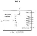
does not correspond to the standard sample. Fig. 8 is a diagram
for indicating a display example in the case that the relevant
standard sample is not present. In Fig. 8, reference numeral
13 shows a calculation mode display unit, reference numeral 14
indicates a display portion of the relevant refrigerant,
reference numeral 15 represents a display portion indicative
of concentration of the respective refrigerants, and reference
numeral 16 shows a display portion of a message supplied from
the multi-component analyzing apparatus 1.
In the case shown in Fig. 8, the mode display portion 13
displays a display result obtained by the B mode . Also, since
there is no relevant refrigerant, such a symbol "---" is
displayed on the display portion 14, and none of relevant
fluorocarbon name is displayed. Also, the display portion 15
displays thereon weight % of the respective fluorocarbon
containing amounts larger than, or equal to a predetermined
amount. It should be noted that symbol "**" shows a component
lower than, or equal to a detection limit. In addition, a
display content "CONTAMINATED" of the message display portion
16 indicates such a message that the measuring-subject sample
S is contaminated by other components.
A step "S6" corresponds to a step which is executed when
it is so judged in the previous step S4 that there is such a
standard sample whose component ratios are made coincident with
each other with the range of the shift of 0.1. In this step,
the above-explained standard sample correction coefficient rli
may be selected from the number 1 of the selected standard sample,
and concentration x1 to x7 of the respective components is again
calculated by executing the calculation defined in the
above-explained formula (7). Then, the values of the
concentration x1 to x7 are corrected by executing the
proportional calculation in such a manner that a total value
of the calculated concentration x1 to x7 becomes equal to 1.
Also, a minus value of the concentration x1 to x7 is calculated
as "0".
A step "S7" corresponds to such a step for judging as to
whether or not such a standard sample made of either the single
components or the mixed components is present in which the
respective component ratios of the calculated concentration x1
to x7 are made coincident with each other within the range of
the shifts of 0.02. In this step, when it is so judged that
the relevant standard sample is not present, the process
operation jumps to a step S8.
In other words, the step S8 is such a step in which the
respective component concentration x1 to x7 of the mixed
fluorocarbon is directly displayed on the display portion 7.
It should be noted that in Fig. 9, the calculation mode display
portion 13 indicates a measurement result obtained by the B mode,
and the refrigerant display portion 14 displays a name of such
a sample ("R407C" in this example) which is selected at the
previous step 4 and resembles the relevant standard sample at
the highest degree.
On the other hand, a step "S9" corresponds to a step for
displaying respective component concentration x1 to x7 on the
display unit 7 in such a case that it is so judged in the previous
step S7 that the component ratio is identical to that of the
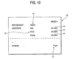
standard sample. Fig. 10 is a diagram for indicating an example
of a screen displayed in the step S9. In Fig. 10, reference
numeral 17 indicates a display portion which displays thereon
weight % of other components, very small amounts of which are
contained in the standard sample. In this example, this display
portion 17 indicates that these very small amounts are
substantially equal to detection limit amounts. Also, the
calculation mode display portion 13 indicates a measurement
result acquired by the A mode, and also indicates that the
analyzing operation by the multi-component analyzing apparatus
1 could be carried out in the highest precision.
As indicated in Fig. 10, at such a stage that the
measurement result could be acquired in the A mode in the highest
precision, the mode display is arbitrarily switched between the
B mode and the A mode by using the manual switching buttons 8e
and 8d shown in Fig. 1, so that the concentration of the
respective components may be confirmed.
Fig. 11 is a diagram for indicating such an example as
to both measurement values (absorbances) y2, y3, and calculation
values f2(0, x2, x3, 0, 0, 0, 0), and f3(0, x2, x3, 0, 0, 0, 0).
That is, in the above-described example, the measurement values
y2 and y3 are actually measured while concentration of
fluorocarbon (R125, R134a) of two components is varied, and
these calculation values f2 and f3 are obtained by substituting
the concentration x2 and x3 for the formula (6).
In Fig. 11, symbol "X" shows an actually-measured value
of the absorbances y2; symbol "*" denotes an actually-measured
value of the absorbance y3; symbol "◆" which is substantially
overlapped with the symbol "X" represents a value of the
calculation formula (containing mutual interference
correction) f2(0, x2, x3, 0, 0, 0, 0) ; and also, symbol "▪" which
is substantially overlapped with the symbol "X" shows a value
of the calculation formula (containing mutual interference
correction) f3(0, x2, x3, 0, 0, 0, 0). Also, curves "C125" and
"C134a" in Fig. 9 correspond to such curves made by connecting
the respective points of the above-explained calculation values
f2(0, x2, x3, 0, 0, 0, 0) and f3(0, x2, x3, 0, 0, 0, 0), whereas
curves "D125" and "D134a" correspond to such curves formed by
connecting the respective points of the measurement values y2
and y3.
As indicated in Fig. 11, the actually-measured values of
the measurement values y2 and y3 are essentially overlapped with
the values of the calculation formulae f2(0, x2, x3, 0, 0, 0,
0) and f3(0, x2, x3, 0, 0, 0, 0) , and also, substantially no error
is present between these values. As apparent from a comparison
result between Fig. 11 and Fig. 13, the analyzing precision of
the present invention 10 times, or higher than that of the prior
art can be improved. In other words, while the complexness of
the analyzing calculation is kept in minimum degree, the
sufficiently high precision can be achieved.
Precisely speaking, since the calculation using the
above-described formula (6) is carried out, the magnitudes of
errors can be reduced from several weight % (prior art) to
approximately 0.2 to 0.3 weight % (present invention), which
represents that the measuring operation can be carried out in
considerably high precision, as compared with the measurement
precision of the prior art. In addition, since the calculation
using the above-explained formula (7) is carried out, the errors
can be further decreased, and thus, may be reduced smaller than,
or equal to 0.1 weight %.
Furthermore, the calculation is carried out by employing
such a formula obtained by expanding the formula (3) instead
of the calculation using the above-described formula (6), so
that resulting precision may be furthermore improved. In this
case, for example, various modifications may be conceived, for
instance, higher dimensional terms higher than, or equal to the
three-dimensional term may be omitted.
In any of these cases, there is such a common point
arranged in the multi-component analyzing apparatus 1 of the
present invention. That is, the calculating process unit 6 may
execute the analyzing process program P capable of executing
the above-described analyzing operation by solving the
simultaneous equation (formula (3), formula (4) etc.) which are
constituted by such equations having the mutual interference
correction terms used to correct the interference adverse
influences among the respective measuring-subject components.
Also, even when another simultaneous equations different from
the above-explained formulae (3) and (4) are employed, since
the mutual interference correction term is provided, a similar
effect to that of the above-explained example may be achieved.
As previously explained, in accordance with the
multi-component analyzing apparatus of the present invention,
even in such a case that the measuring-subject components which
mutually may give the interference adverse influences to each
other are mixed with each other, the analyzing operation can
be carried out in very high precision. Thus, the
multi-component analyzing apparatus whose calculation
precision is considerably improved can be provided.
Second Embodiment
Referring now to drawings, a mixed-refrigerant analyzing
apparatus of the present invention will be described in detail.
Fig. 14 to Fig. 16 indicates one embodiment mode of the present
invention. First, Fig. 14 schematically shows a structural
example of a mixed-refrigerant analyzing apparatus according
to the present invention. In this drawing, reference numeral
101 shows Bombe which has stored thereinto a mixed refrigerant
functioning as sample gas "S", and reference numeral 102
represents a Bombe valve. Reference numeral 103 indicates a
sample gas supplying path used to connect Bombe 101 to a
mixed-refrigerant analyzing apparatus 105 (will be discussed
later). This sample gas supplying path 103 is equipped with
a pressure control device 104.
Reference numeral 105 shows a mixed-refrigerant
analyzing apparatus 105. This mixed-refrigerant analyzing
apparatus 105 is arranged as follows. That is, for instance,
reference numerals 106 and 107 represent a gas inlet and a gas
outlet, respectively, which are formed in the mixed-refrigerant
analyzing apparatus 105. A downstream end of the sample gas
supplying path 103 is connected to the gas inlet 106. Reference
numeral 108 represents a gas path formed between the gas inlet
106 and the gas outlet 107. The sample gas S supplied from the
gas inlet 106 passes through this gas path 108. A flow-rate
controlling needle valve opening/closing-valve 109, an oil
filter 110, a three-way electromagnetic valve 111, a gas
analyzing unit 112, and another gas analyzing unit 113 are
provided in this order from an upperstream side of the gas path
108. The three-way electromagnetic valve 111 is interposed in
the gas path 108 in such a manner that a first port 111a which
is closed when the power supply is turned OFF is connected to
the oil filter 110, and a normally-open second port 111b is
connected to the gas analyzing unit 112. It should be noted
that reference numeral 114 shows a gas ejection (discharge) path
connected to the gas outlet 107, and a downstream side of this
gas ejection path 114 is connected to a properly-provided gas
collecting unit (not shown).
The above-described gas analyzing units 112 and 113
analyze ratios of respective refrigerant components contained
in a mixed refrigerant by utilizing the NDIR method, and are
arranged as shown in, for example, Fig. 15. In other words,
one gas analyzing unit 112 is arranged by a cell 112a, an infrared
light source 112b and a chopper 112c, which are provided on the
side of one window 112a1 of this cell 112a, and also a detecting
unit 112d provided on the side of the other window 112a2 of the
cell 112a. The other gas analyzing unit 113 is arranged by a
cell 113a, an infrared light source 113b and a chopper 113c,
which are provided on the side of one window 113a1 of this cell
113a, and also a detecting unit 113d provided on the side of
the other window 113a2 of the cell 113a.
Then, the cell 112a of the above-explained one gas
analyzing unit 112 is series-connected to the cell 113a of the
other gas analyzing unit 113. The sample gas S is supplied via
the three-way electromagnetic valve 111 to one cell 112a.
positioned on an upperstream side, whereas the sample gas S is
supplied via this cell 112a to the other cell 113a which is
series-connected to the cell 112a in such a manner that this
cell 113a is located on the downstream side of this cell 112a.
Also, the above-described detecting units 112d and 113d
are arranged in order that for example, 7 pieces (7 sorts) of
refrigerant components which are contained in the mixed
refrigerant employed as the sample gas S can be detected by these
two detecting units 112d and 113d. That is to say, in one
detecting unit 112d, three pyroelctric detectors "D1" to "D3"
and three bandpass filters "F1" to "F3" constitute pairs in
correspondence with three sorts of refrigerant components
(R143a, R125, R134a) among seven sorts of the above-described
refrigerant components, and furthermore, as indicated in Fig.
16A, are arranged in such a manner that the circumference is
equally divided by 3. Then, in the other detecting unit 113d,
the four pyroelectric detectors "D4" to "D7" and four bandpass
filters "F4" to "F7" constitute pairs in correspondence with
the remaining four sorts of refrigerant components (R32, R115,
R12, R22) among seven sorts of the above-described refrigerant
components, and furthermore, as indicated in Fig. 16B, are
arranged in such a manner that a circumference is equally
divided by 4.
Then, the seven bandpass filters F
1 to F
7 employed in the
above-described detecting
units 112d and 113d are set in such
a manner that infrared transmission wavelength ranges thereof
are not adversely influenced by interference caused by other
refrigerant components and S/N ratio is large. Also, the seven
bandpass filters "F
1" to "F
7" are subdivided into two filter
groups in response to absorbances of refrigerant components
corresponding to the measuring subject components detected by
the respective bandpass filters F
1 to F
7. Thus, the bandpass
filters F
1 to F
3 corresponding to such refrigerant components
whose absorbances are large are stored into the detecting
unit
112d, whereas the bandpass filters F
4 to F
7 corresponding to
such refrigerant components whose absorbances are small are
stored into the detecting
unit 113d. Furthermore, as to the
seven bandpass filters F
1 to F
7, transmission central wave
numbers thereof are set as shown in, for example, the
below-mentioned table 4 in correspondence with the infrared
absorption spectra of the seven refrigerant components.
| unit : cm-1 |
| | R143 | R125 | R134a | R32 | R115 | R12 | R22 |
| central wave number | 1235 | 1215 | 1187 | 1083 | 981 | 920 | 813 |
Returning back to Fig. 14, reference numeral 115
indicates a zero gas inlet formed in the mixed-refrigerant
analyzing apparatus 105. A zero gas supplying path 116 is
formed between this zero gas inlet 115 and a third port 111c
which is opened when the power supply of the three-way
electromagnetic valve 111 is turned OFF. A filter 117 and a
suction pump 118 are provided in this order within this zero
gas supplying path 116. Then, this zero gas supplying path 116
supplies zero gas "Z" to the cells 112a and 113a of the gas
analyzing units 112 and 113 having the above-described
structures via the three-way electromagnetic valve 111. In
this embodiment mode, the mixed-refrigerant analyzing
apparatus 105 is arranged in such a manner that air "A" is
conducted from the zero gas inlet 115, this conducted air A is
filtered by the filter 117 to become clean air, and then, this
clean air may become the zero gas Z.
Although not shown in the drawing, a calculation control
apparatus (for example, personal computer) is provided in the
above-described mixed-refrigerant analyzing apparatus 105,
while this calculation control apparatus may sequentially
control the respective structural units of this analyzing
apparatus 105, and may perform concentration calculations
(component ratio calculations) of a plurality (seven
refrigerant components in this example) of refrigerant
components based upon gas analysis results outputted from the
gas analyzing units 112 and 113.
A description will now be made of measuring operations
of a mixed refrigerant with employment of the mixed-refrigerant
analyzing apparatus 105 with employment of the above-explained
arrangement. The measurement key of the calculation control
apparatus is manually turned ON so as to turn ON the three-way
electromagnetic valve 111. Then, under this condition, the
Bombe value 102 is manually opened in order to supply a mixed
refrigerant stored in Bombe 101 as the sample gas "S" to the
mixed-refrigerant analyzing apparatus 105 of this embodiment
mode of the present invention. The sample gas S supplied to
the mixed-refrigerant analyzing apparatus 105 is entered
through the needle valve 109, the oil filter 110, and the
three-way electromagnetic valve 111 to the cell 112a of the gas
analyzing unit 112 provided on the upperstream side. Then, the
sample gas S which has passed through this cell 112a is entered
into the cell 113a of the gas analyzing unit 113 provided on
the downstream side. In these gas analyzing units 112 and 113,
while the sample gas S is supplied to the cells 112a and 113a,
the analyzing operation of the sample gas S is carried out.
Since this sample gas analyzing operation is carried out, a
sensor signal rises, and thereafter, the respective gas
analyzing units 112 and 113 execute sampling operations of data.
As a consequence, a measurement signal "s" is obtained every
refrigerant component from each of the gas analyzing units 112
and 113. Then, the sample gas S outputted from the gas analyzing
unit 113 provided on the downstream side is entered from the
gas outlet 107 into the gas ejection path 114, and thereafter,
is collected. Also, after the three-way electromagnetic valve
111 has been turned ON for a predetermined time duration, this
three-way electromagnetic valve 111 is turned OFF. After this
three way electromagnetic valve 111 has been turned OFF, and
further, a certain time has elapsed, the Bombe valve 102 is
manually closed.
Then, when the suction pump 118 is turned ON, the zero
gas Z is entered from the zero gas supplying path 116 via the
three-way electromagnetic valve 111 to the cell 112a of the gas
analyzing unit 112 provided on the upper stream side, and the
zero gas Z which has passed through this cell 112a is entered
into the cell 113a of the gas analyzing unit 113 provided on
the downstream side, and also, the sensor signal which has rised
falls downwardly. In the gas analyzing units 112 and 113, while
the zero gas Z is supplied to the cells 112a and 113a, a zero
measuring operation based upon the zero gas "Z" is carried out.
As a result, a zero signal "z" is obtained every refrigerant
component from each of the gas analyzing units 112 and 113. Then,
the zero gas Z which has sequentially flown through the gas
analyzing units 112 and 113 is entered from the gas outlet 107
to the gas ejection path 114, and thereafter, is collected.
Then, in the calculation control apparatus, a ratio of
the plural refrigerant components contained in the sample gas
S may be obtained by, for example, calculating a ratio [log
(s/z)] based upon the measurement signals "s(s2 to s7)"
outputted from a plurality of pyroelectric detectors D1 to D7
which are provided in correspondence with a plurality of
refrigerant components acquired when the sample gas is measured,
and also, the zero signals "z(z1 to z7))" derived from the
pyroelectric detectors D1 to D7, which are acquired when the
zero measuring operation is carried out.
As previously explained, in the mixed-refrigerant
analyzing apparatus of this embodiment mode, the infrared
transmission central wave numbers of the seven bandpass filters
F1 to F7 are set as indicated in the above-described table 4,
and are employed so as to detect the seven sorts of refrigerant
components R143a, R125, R134a, R32, R115, R12, and R22 contained
in the sample gas S. As a consequence, as shown in Fig. 17,
infrared absorption spectra (namely, curves denoted by symbols
"A1" to "A7" in this drawing) of the above-explained seven
refrigerant components may mutually correspond to infrared
transmission characteristics (namely, curves indicated by
symbols "B1" to "B7" in this drawing) of the respective bandpass
filters F1 to F7. Accordingly, deferent from the conventional
mixed-refrigerant analyzing apparatus, the mixed-refrigerant
analyzing apparatus of the embodiment mode can analyze the
plural refrigerant components of the mixed refrigerant in
higher precision while suppressing the mutual interference
caused by the plural refrigerant components as much as possible.
Also, as indicated in Fig. 19C and Fig. 19D, the respective
absorbances of the refrigerant components R32 and R22 do not
receive the adverse influences from each other, so that such
absorbance characteristics having clear steep degrees can be
obtained.
Measurement errors produced when the infrared
transmission central wave numbers of the seven bandpass filters
F
1 to F
7 are set to those shown in the above-described table
4 are given as shown in the below-mentioned table 5.
| | R143a | R125 | R134a | R32 | R115 | R12 | R22 |
| Prior art | less than 1% | 1.5% | less than 1% | 2.6% | less than 1% | 1.5%. | 3.9% |
| embodiment | less than 1% | less than 1% | less than 1% | less than 1% | less than 1% | less than 1% | less than 1% |
In the above table 5, numerals of an upper stage are equal
to those of the table 2 which are again described. As easily
understood from this table 5, the mutual interference degrees
caused by the seven refrigerant components can be suppressed
as many as possible, and the respective refrigerant components
can be analyzed in higher precision.
It should be noted that the central wave numbers of the
seven bandpass filters F
1 to F
7 are not limited only to the
central wave numbers shown in the above-described table 4.
Alternatively, as to the respective central wave numbers, for
example, a slight allowable range may be provided as indicated
in the below-mentioned table 6.
| unit: cm-1 |
| | R143a | R125 | R134a | R32 | R115 | R12 | R22 |
| upper limit value of central wave number | 1235 | 1220 | 1192 | 1088 | 1000 | 933 | 820 |
| lower limit value of central wave number | 1222 | 1205 | 1180 | 1065 | 981 | 908 | 798 |
On the other hand, in the above-described embodiment mode,
the mutual interference occurred in the refrigerant components
R32 and R22 has been described. In particular, the central wave
numbers of the bandpass filters F
4 and F
7 corresponding to these
refrigerant components R32 and R22 have been changed to be again
set. Alternatively, as to other refrigerant components R143a
and R125, the central wave numbers of the bandpass filters F
1
and F
4 corresponding to these refrigerant components may be
changed to be again set. The below-mentioned table 7 indicates
an example of upper limit values and lower limit values as to
the central wave numbers of the seven bandpass filters F
1 to
F
7 in this alternative case.
| uni t : cm-1 |
| | R143a | R125 | R134a | R32 | R115 | R12 | R22 |
| upper limit value of central wave number | 1269 | 1151 | 1192 | 1088 | 1000 | 933 | 820 |
| lower limit value of central wave number | 1263 | 1137 | 1180 | 1065 | 981 | 908 | 798 |
Since the infrared transmission central wave numbers of
the seven bandpass filters F1 to F7 are set as indicated in the
above-described table 7, and are employed so as to detect the
seven sorts of refrigerant components R143a, R125, R134a, R32,
R115, R12, and R22, as shown in Fig. 18, infrared absorption
spectra (namely, curves denoted by symbols "A1" to "A7" in this
drawing) of the above-explained seven refrigerant components
may mutually correspond to infrared transmission
characteristics (namely, curves indicated by symbols "B1" to
"B7" in this drawing) of the respective bandpass filters F1 to
F7. Therefore, the mixed-refrigerant analyzing apparatus of
the embodiment mode can analyze the plural refrigerant
components of the mixed refrigerant in higher precision while
suppressing the mutual interference caused by the plural
refrigerant components as much as possible.
Alternatively, both the upper limit values and the lower
limit values of the central wave numbers of the bandpass filters
F1 and F2 used to detect the refrigerant components R143a and
R125 may be set as follows. That is to say,
(1) as to the refrigerant component R143a, the upper limit
value and the lower limit value of the bandpass filter F1 are
set to 1222 to 1235 cm-1, whereas with respect to the refrigerant
component R125, the upper limit value and the lower limit value
of the bandpass filter F2 are set to 1137 to 1151 cm-1.
Otherwise, (2) as to the refrigerant component R143a, the
upper limit value and the lower limit value of the bandpass
filter F1 are set to 1263 to 1269 cm-1, whereas with respect to
the refrigerant component R125, the upper limit value and the
lower limit value of the bandpass filter F2 are set to 1205 to
1220 cm-1.
Then, in any one of the above-described alternative cases
(1) and (2), both the upper limit values and the lower limit
values of the central wave numbers of the bandpass filters F3
to F7 used to detect other five refrigerant components (R134a,
R32, R115, R12, R22) are made equal to those shown in either
the table 6 or the table 7.
In any one of these alternative cases, the infrared
absorption spectra of the plural refrigerant components may
mutually correspond to the infrared transmission
characteristics of the respective bandpass filters, so that
these plural refrigerant components may be analyzed in higher
precision, while the mutual interference may be suppressed as
much as possible.
It should be noted that in the mixed-refrigerant
analyzing apparatus with employment of the above-explained
arrangement, both the bandpass filters F1 to F7 and the detectors
D1 to D7, which correspond to the respective refrigerant
components, are classified into two groups in response to the
absorbances of the respective refrigerant components, and also,
the cells 112a and 113a having the different cell lengths in
correspondence with the respective groups . In this case, the
cell length of the cell 112a corresponding to the detecting unit
112d may be made shorter than the cell length of the cell 113a
corresponding to the detecting unit 113d so as to control the
absorbance levels between the respective groups, while the
detecting unit 112d stores thereinto the bandpass filters F1
to F3 and the detectors D1 to D3, which are employed so as to
detect the refrigerant components having the large absorbances,
whereas the detecting unit 113d stores thereinto the bandpass
filters F4 to F7 and the detectors D4 to D7 which are employed
so as to detect the refrigerant components having the small
absorbances. In such a case, linearity of the measuring
sensitivities as to all of the refrigerant components may be
maintained within a necessary range. As a result, measurement
results may be obtained in higher precision.
It should also be noted that in the above-described
embodiment mode, such an example has been exemplified that the
seven refrigerant components are present in the mixed
refrigerant, and all of these seven refrigerant components are
analyzed. However, the present invention is not limited only
to this exemplified example, but may be modified. For example,
a mixed refrigerant may be constituted by two, or more sorts
of refrigerant components. Also, in the above-explained
embodiment mode, the mixed-refrigerant analyzing apparatus 105
is arranged by a plurality of gas analyzing units 112 and 113.
Instead of this arrangement, as a single gas analyzing unit,
a single cell having a plurality of cell lengths may be employed
in this gas analyzing unit.
As previously explained, in accordance with the
mixed-refrigerant analyzing apparatus of the present invention,
a plurality of refrigerant components corresponding to the
measuring-subject components can be analyzed in higher
precision, while the mutual interference caused by these plural
refrigerant components can be suppressed as much as possible.