EP1398572A2 - Dual-mode nozzle assembly with passive tip cooling - Google Patents
Dual-mode nozzle assembly with passive tip cooling Download PDFInfo
- Publication number
- EP1398572A2 EP1398572A2 EP03076978A EP03076978A EP1398572A2 EP 1398572 A2 EP1398572 A2 EP 1398572A2 EP 03076978 A EP03076978 A EP 03076978A EP 03076978 A EP03076978 A EP 03076978A EP 1398572 A2 EP1398572 A2 EP 1398572A2
- Authority
- EP
- European Patent Office
- Prior art keywords
- nozzle
- passageway
- dual
- cooling fluid
- sleeve
- Prior art date
- Legal status (The legal status is an assumption and is not a legal conclusion. Google has not performed a legal analysis and makes no representation as to the accuracy of the status listed.)
- Granted
Links
Images

Classifications
-
- F—MECHANICAL ENGINEERING; LIGHTING; HEATING; WEAPONS; BLASTING
- F23—COMBUSTION APPARATUS; COMBUSTION PROCESSES
- F23R—GENERATING COMBUSTION PRODUCTS OF HIGH PRESSURE OR HIGH VELOCITY, e.g. GAS-TURBINE COMBUSTION CHAMBERS
- F23R3/00—Continuous combustion chambers using liquid or gaseous fuel
- F23R3/28—Continuous combustion chambers using liquid or gaseous fuel characterised by the fuel supply
- F23R3/286—Continuous combustion chambers using liquid or gaseous fuel characterised by the fuel supply having fuel-air premixing devices
-
- F—MECHANICAL ENGINEERING; LIGHTING; HEATING; WEAPONS; BLASTING
- F23—COMBUSTION APPARATUS; COMBUSTION PROCESSES
- F23D—BURNERS
- F23D2214/00—Cooling
-
- F—MECHANICAL ENGINEERING; LIGHTING; HEATING; WEAPONS; BLASTING
- F23—COMBUSTION APPARATUS; COMBUSTION PROCESSES
- F23D—BURNERS
- F23D2900/00—Special features of, or arrangements for burners using fluid fuels or solid fuels suspended in a carrier gas
- F23D2900/00008—Burner assemblies with diffusion and premix modes, i.e. dual mode burners
Definitions
- This invention relates generally to the field of fuel nozzles and, more particularly, to a dual-mode flame holding, tip-cooled combustion engine fuel nozzle.
- Combustion engines are machines that convert chemical energy stored in fuel into mechanical energy useful for generating electricity, producing thrust, or otherwise doing work. These engines typically include several cooperative sections that contribute in some way to this energy conversion process.
- gas turbine engines air discharged from a compressor section and fuel introduced from a fuel supply are mixed together and burned in a combustion section. The products of combustion are harnessed and directed through a turbine section, where they expand and turn a central rotor.
- the rotor produces shaft horsepower or torque; this output shaft may, in turn, be linked to devices such as an electric generator to produce electricity.
- DLN dry, low-NO x
- DLN combustors typically provide lowered amounts of unwanted emissions by lowering the burning temperature and by premixing fuel and air providing independent flows of fuel to two or more discrete groups or “stages” of combustors, with each stage contributing in a different manner to the overall combustion process.
- Two common stages found in DLN arrangements are the "pilot" and “main” stages. Quite often, the pilot stage is a "diffusion" nozzle capable of holding a flame.
- Diffusion-type nozzles are quite stable, but they inherently include fuel-rich regions which provide a source of combustion hot spots that lead to the formation of unwanted NOx emissions.
- typically only one diffusion nozzle is used in a given combustor.
- the main stage nozzles operate in a "premix" mode, producing a mixture of fuel and air that burns through interaction with other flames, such as the fuel-rich flame produced by the pilot stage.
- This arrangement is stable and produces relatively-low NOx emissions, when compared to earlier approaches.
- the diffusion-type pilot nozzle produces localized regions of high temperature or "hot spots" and remains a source of unwanted NOx emissions, making this approach unsuitable for some settings.
- a dual-mode, flame-stable nozzle that provides tip cooling and selectively dispense diffusion fuel or a mixture of fuel and air in a simplified manner.
- the nozzle should transmit cooling air passively, through a dedicated passage that eliminates the need for complex valve arrangements.
- the nozzle should also include discrete fluid-guiding conduits that are sealed in a leak-resistant manner with reduced reliance upon sliding joints and bellows arrangements.
- the instant invention is a dual-mode, flame-holding nozzle for a gas turbine combustion engine that provides passive tip cooling and selective dispersion of diffusion fuel or mixed fuel and air.
- the nozzle includes several elongated sleeves that cooperatively form discrete passageways adapted to transmit fluids through the nozzle.
- the nozzle includes conduits that allow fuel and cooling air to reach designated fuel and cooling passageways without mixing. This arrangement advantageously ensures that air used to cool the nozzle does not become flammable, thereby reducing the chances of unwanted flashback occurrences.
- Portions of the nozzle sleeves are also strategically arranged to transmit fluids in a manner that provides substantially-uniform thermal expansion, thereby reducing the need for sliding joints and/or bellows arrangements.
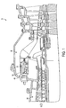
- the nozzle 10 of the present invention is especially suited for use in a combustion system 36 using nozzles that operate in a dual-mode arrangement, but could have application as a single-mode nozzle, as well.
- the nozzle 10 resembles an elongated cylinder having several substantially-concentric tubes 12, 14, 15, 16, 18 that cooperatively form a collection of annular chambers 20, 22, 23, 24, 26 which facilitate controlled flow of fluids through the nozzle.
- the nozzle 10 is characterized by a first end 40 and an opposite second end 42, with fluids flowing generally from the first end to the second end during operation.
- the nozzle 10 also includes conduit groups 28, 30 that advantageously allow fuel 32 and tip cooling air 34 to reach designated passageways within the nozzle. More particularly, the first conduit group 28 allows fuel 32 to move from the second passageway 22 into the first passageway 20, to interact with air 52 located therein.
- the second conduit group 30 beneficially allows cooling air 34 to reach the third passageway 24 from a location radially outward of the fuel-containing second passageway 22, without allowing fuel 32 to contaminate the cooling air.
- Third passageway exits 60 allow cooling air 34 to leave the third passageway exits 60 and cool the nozzle second end 42.
- a supplemental passageway 23 disposed between the second and third passageways 22,24 supplies supplemental diffusion fuel 74 to the nozzle tip 42.
- the conditions within an associated combustor 46 at the nozzle second end 42 ensure the flame is maintained/self-stable.
- fuel is supplied through diffusion holes 61 at a velocity range conducive to stable conditions.
- the fuel injected through the holes 61 mixes with the air passing through the annulus 20 combustion immediately downstream of nozzle tip 42.
- the outer shroud 12 may diverge outward, as it extends downstream beyond tip 42, forming a cone that aides in stabilizing the flame.
- fuel is injected through holes 58 into the air stream 52. This fuel/air mixture flows through passageway 20 and enters the flame front immediately downstream of the nozzle tip 42. Adequate velocity is maintained in passageway 20 to prevent the flame from proceeding upstream.
- the nozzle 10 will now be described in further detail.
- the nozzle 10 of the present invention is especially suited for use as a flame-holding, dual-mode nozzle capable of operating in a premix mode and a diffusion mode.
- Premix fuel 32 travels from a source of fuel (not shown) through apertures 50 at the upstream end 40 of the nozzle 10 and enters a nozzle second passageway 22.
- the fuel 32 flows through the second passageway 22 and travels into the first passageway 20, where it forms a flammable mixture with air 52 located therein.
- the flammable mixture flows toward the nozzle second end 42; combustion may be initiated by an igniter 76 that is positioned in a nozzle inner passageway 26 or located remotely.
- the inner passageway 26 may be plugged or adapted to transmit a fluid to the nozzle tip 42.
- the nozzle also contains a supplemental passageway 23 through which supplemental fuel 74 may be transmitted to the nozzle second end 42 to permit diffusion-style combustion.
- Tip cooling air 34 passes through the third passageway and prevents tip melting, as described below.
- the nozzle 10 includes a fluid supply hub 70 includes three groups of apertures 48, 49, and 50 that allow premix air 52 and premix fuel 32, and supplemental diffusion fuel 74 respectively, to pass through the flange and enter corresponding passageways, or chambers, formed by the nozzle sleeves 14,15,16, and 18. More particularly, the first set of apertures 48 facilitates entry of premix air 52 into the nozzle first passageway 20. Similarly, the second set of apertures 50 allows premix fuel 32 to enter the nozzle second passageway 22, and the set of supplemental apertures 49 allows diffusion fuel to reach the supplemental passageway 23.
- conduits 28,30 beneficially allow premix fuel 32 and cooling air 34, respectively, to flow between portions of the nozzle 10 without becoming co-mingled.
- the first group of conduits 28 includes fuel injection members 54 that are each characterized by an entrance 56 in fluid communication with the second passageway 22 and an exit 58 in fluid communication with the first passageway 20.
- the fuel injection members 54 are hollow and include a group of exit holes 58. With this arrangement, the fuel injection members 54 transmit premix fuel 32 into the first passageway 20, where it mixes with premix air 52 and creates a flammable mixture of fuel and air.
- the fuel injection members 54 may be adapted to increase the turbulence within the first passageway 20 by, for example, having a substantially-airfoil-shaped cross-section.
- Other mixing or turbulence-increasing elements including, discrete swirler vanes or other suitable components, may also be provided as desired.
- first set of conduits 28 need not include fuel injection members 54, and may take a variety of forms that permit fuel to travel from the second passageway 22 to the first passageway 20.
- premix fuel 32 fuel may be dispersed directly through the first sleeve 14.
- the fuel 32 may exit the second passageway 22 from a variety of axially-different locations.
- the outer wall 12 is not required for operation; the first passageway 20 may be bounded by the first sleeve 14 and a supplemental sleeve or partition, such as the combustor wall 82 or other suitable boundary, as seen in Figure 1.
- the second group of conduits 30 provide dedicated paths through which air 34 reaches the third passageway 24.
- the air 34 in the third passage acts as cooling air, flowing downstream and through third passageway exits 60 to cool the nozzle tip or second end 42.
- Each of the conduits 30 in the second conduit group includes an entrance 62 in fluid communication with a source of cooling air (such as a compressor 80 coupled with the associated combustion turbine engine 38, seen in Figure 1) and an opposite exit 64 in fluid communication with the third passageway 24.
- a source of cooling air such as a compressor 80 coupled with the associated combustion turbine engine 38, seen in Figure 1
- the second conduit entrances 62 are in fluid communication with compressor discharge air 66
- the second group of conduits 30 directs a portion of the compressor discharge air into the third passageway 24 to, as noted above, cool the nozzle second end 42.
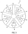
- each of the cooling air conduits 30 is oriented radially within the fluid supply hub 70.
- the cooling fluid conduits 30 lie between the premix air, supplemental fuel, and premix fuel apertures 48, 49, and 50, which extend longitudinally through the fluid supply hub 70.
- this arrangement advantageously allows the entrances 62 of the cooling fluid conduits 30 to be located radially-outboard of the fuel 32 and the cooling fluid conduit exits 64 to be located radially-inboard of the premix fuel.
- the cooling fluid conduit entrances 62 are located upstream of the locations where fuel 32 joins the compressor discharge air 66.
- This arrangement advantageously allows one source of air 66 to provide air for several purposes, while safely ensuring that the air 34 used for cooling is fuel-free and not flammable.
- sliding interface 59 permits relative motion at the second end of the nozzle 42, thereby accommodating thermal growth differences during operation. With this arrangement, air, and not fuel, flows within passageway 34. This advantageously ensures that fluid which may emanate from the interface 59 is not flammable.
- cooling fluid conduits 30 need not be radially arranged; any suitable orientation that allows the cooling air 34 to enter the third passageway 24 from a location upstream of the premix fuel 32 would suffice. Radial arrangement of the cooling fluid conduits 30 does, however, provide enhanced manufacturability. It is also noted that the cooling fluid conduits 30 need not be located in a fluid supply hub 70; other locations may be used as desired. For example, the cooling fluid conduits 30 may extend through a component that supports the nozzle 10, such as a mounting flange (not shown).
- compressor discharge air 66 substantially surrounds the nozzle first end 40, and that such air may enter the first passageway by travelling around the nozzle first end and flowing between the outer wall 12 and first sleeve 14, thereby eliminating the need for the first group of apertures 48.
- the cooling fluid passageway exits 60 are in fluid communication with the first passageway 20, and a pressure drop across the first passageway helps move the flow of cooling air 34 through the third passageway 24 and exit 60.
- the pressure difference also beneficially prevents the air/fuel mixture from entering passage 24.
- the nozzle 10 of the present invention provides a passive tip cooling system that employs a dedicated, air-only cooling fluid, eliminating the need for flows of purge fluid or fuel-blocking members.
- the nozzle 10 of the present invention has been described as diverting a portion of the compressor discharge air 66 into the third passageway 24 to provide cooling air 34, other arrangements may be used.
- the entrances 62 of the cooling fluid conduits 30 may be in fluid connection with other sources of cooling air, including a cooling air manifold (not shown).
- cooling air 34 may be motivated through the third passageway 24 by a pump (not shown) or other suitable flow-inducing components.
- the first and second sleeves 14,16 are each exposed to compressor discharge air 66 and premix fuel 32.
- the thermal expansion exhibited by the first sleeve 14 is substantially, if not identically, the same as the thermal expansion exhibited by the second sleeve 16.
- the first sleeve 14 may advantageously be connected to the second sleeve 16 in a rigid manner, without a flexible connection or slip-fit arrangement. This advantageously makes the nozzle 10 more reliable, increases the nozzle life span, and makes the nozzle less likely to leak.
- the supplemental sleeve 15 is exposed only to fuel and expands differently than the first and second sleeves 14,16.
- a bellows element 84 disposed in the supplemental sleeve accommodates thermal expansion differences between the sleeves without stressing the nozzle.
Landscapes
- Engineering & Computer Science (AREA)
- Chemical & Material Sciences (AREA)
- Combustion & Propulsion (AREA)
- Mechanical Engineering (AREA)
- General Engineering & Computer Science (AREA)
- Spray-Type Burners (AREA)
- Turbine Rotor Nozzle Sealing (AREA)
Abstract
Description
Claims (17)
- A dual-mode fuel nozzle for a combustion engine, said nozzle comprising:an elongated first sleeve characterized by an upstream end and an opposite downstream end;a supplemental sleeve disposed radially inward of said first sleeve, said first and supplemental sleeves defining a first fuel passageway therebetween, said first fuel passageway including an inlet and an exit, said inlet being adapted for fluid communication with a source of fuel;a second sleeve disposed radially inward of said supplemental sleeve, said supplemental and second sleeves defining a supplemental fuel passageway therebetween, said supplemental fuel passageway including an inlet and an exit, said an inlet being adapted for fluid communication with a source of fuel;a third sleeve disposed radially inward of said second sleeve, said second and third sleeves defining a cooling fluid passageway therebetween, said cooling fluid passageway having an inlet and an exit; anda cooling fluid conduit adapted to fluidly connect said cooling fluid passageway with a source of cooling fluid, said conduit having a conduit entrance located upstream of said fuel passageway exit and a conduit exit in fluid communication with said cooling fluid passageway inlet,whereby said cooling fluid conduit, said cooling fluid passageway, and said fuel passageways cooperatively ensure that cooling fluid passing through said cooling fluid passageway exit is substantially fuel-free during operation.
- The dual-mode fuel nozzle of Claim 1, wherein said cooling fluid is air discharged from a compressor operatively associated with said combustion engine.
- The dual-mode fuel nozzle of Claim 1, wherein said first sleeve cooperatively forms an outer passageway with an outer boundary member spaced radially outward from said first sleeve, said outer passageway being in fluid communication with said fuel passageway exit, said outer passageway including an upstream entrance and a downstream exit, said entrance being adapted for fluid communication with a source of air.
- The dual-mode fuel nozzle of Claim 3, wherein said outer boundary member is an outer wall disposed around a portion of said first sleeve.
- The dual-mode fuel nozzle of Claim 3, further including a mixing member disposed within said outer passageway, said mixing member being adapted to at least partially produce said pressure drop.
- The dual-mode fuel nozzle of Claim 3, wherein said cooling fluid is motivated through said cooling fluid passageway substantially by a pressure drop between said cooling fluid conduit entrance and said cooling fluid exit.
- The dual-mode fuel nozzle of Claim 6, wherein said cooling fluid includes air discharged from a compressor operatively associated with said combustion engine.
- The dual-mode fuel nozzle of Claim 6, wherein said pressure drop is at least partially induced by a mixing member disposed within said outer passageway.
- The dual-mode fuel nozzle of Claim 6, wherein said outer wall and said first sleeve are oriented to at least partially induce said pressure drop.
- The dual-mode fuel nozzle of Claim 9, wherein said pressure drop is at least partially induced by a mxing member disposed within said outer passageway.
- The dual-mode fuel nozzle of Claim 3, wherein:said first sleeve and said second sleeve is each characterized by a first surface and an opposite second surface, each of said first surfaces being arranged for contact with a first fluid having a first temperature and each of said second surfaces being arranged for contact with a second fluid having a second temperature, wherein said contact produces substantially-equal thermal expansion in said first and second sleeves.
- The dual-mode fuel nozzle of Claim 11, wherein:said first and second sleeves are joined together in a rigid relationship, whereby said substantially-equal thermal expansion facilitates said rigid relationship.
- The dual-mode fuel nozzle of Claim 3 further comprising a bellows member disposed within said supplemental sleeve.
- The dual-mode fuel nozzle of Claim 3 further comprising a mounting flange adjacent an upstream end of said nozzle, said cooling fluid conduit being disposed in said mounting flange.
- The dual-mode fuel nozzle of Claim 14 wherein said cooling fluid conduit is oriented in a substantially-radial relationship with respect to a longitudinal axis of said nozzle.
- The dual-mode fuel nozzle of Claim 3 further comprising a fluid transfer member adjacent an upstream end of said nozzle, said cooling fluid conduit being disposed in said fluid transfer member.
- The dual-mode fuel nozzle of Claim 16 wherein said cooling fluid conduit is oriented in a substantially-radial relationship with respect to a longitudinal axis of said nozzle.
Applications Claiming Priority (2)
| Application Number | Priority Date | Filing Date | Title |
|---|---|---|---|
| US10/241,352 US6786046B2 (en) | 2002-09-11 | 2002-09-11 | Dual-mode nozzle assembly with passive tip cooling |
| US241352 | 2002-09-11 |
Publications (3)
| Publication Number | Publication Date |
|---|---|
| EP1398572A2 true EP1398572A2 (en) | 2004-03-17 |
| EP1398572A3 EP1398572A3 (en) | 2010-07-21 |
| EP1398572B1 EP1398572B1 (en) | 2016-11-30 |
Family
ID=31887752
Family Applications (1)
| Application Number | Title | Priority Date | Filing Date |
|---|---|---|---|
| EP03076978.0A Expired - Lifetime EP1398572B1 (en) | 2002-09-11 | 2003-06-26 | Dual-mode nozzle assembly with passive tip cooling |
Country Status (2)
| Country | Link |
|---|---|
| US (1) | US6786046B2 (en) |
| EP (1) | EP1398572B1 (en) |
Cited By (2)
| Publication number | Priority date | Publication date | Assignee | Title |
|---|---|---|---|---|
| EP2182290A4 (en) * | 2007-08-29 | 2014-06-18 | Mitsubishi Heavy Ind Ltd | COMBUSTION CHAMBER FOR GAS TURBINE |
| US8991188B2 (en) | 2011-01-05 | 2015-03-31 | General Electric Company | Fuel nozzle passive purge cap flow |
Families Citing this family (28)
| Publication number | Priority date | Publication date | Assignee | Title |
|---|---|---|---|---|
| JP3495730B2 (en) * | 2002-04-15 | 2004-02-09 | 三菱重工業株式会社 | Gas turbine combustor |
| US7117675B2 (en) * | 2002-12-03 | 2006-10-10 | General Electric Company | Cooling of liquid fuel components to eliminate coking |
| US20060191268A1 (en) * | 2005-02-25 | 2006-08-31 | General Electric Company | Method and apparatus for cooling gas turbine fuel nozzles |
| US20070193272A1 (en) * | 2006-02-21 | 2007-08-23 | Woodward Fst, Inc. | Gas turbine engine fuel injector |
| US7690203B2 (en) * | 2006-03-17 | 2010-04-06 | Siemens Energy, Inc. | Removable diffusion stage for gas turbine engine fuel nozzle assemblages |
| US7762070B2 (en) * | 2006-05-11 | 2010-07-27 | Siemens Energy, Inc. | Pilot nozzle heat shield having internal turbulators |
| US20080078182A1 (en) * | 2006-09-29 | 2008-04-03 | Andrei Tristan Evulet | Premixing device, gas turbines comprising the premixing device, and methods of use |
| EP2179222B2 (en) * | 2007-08-07 | 2021-12-01 | Ansaldo Energia IP UK Limited | Burner for a combustion chamber of a turbo group |
| US7966820B2 (en) * | 2007-08-15 | 2011-06-28 | General Electric Company | Method and apparatus for combusting fuel within a gas turbine engine |
| US7578130B1 (en) * | 2008-05-20 | 2009-08-25 | General Electric Company | Methods and systems for combustion dynamics reduction |
| US8281595B2 (en) * | 2008-05-28 | 2012-10-09 | General Electric Company | Fuse for flame holding abatement in premixer of combustion chamber of gas turbine and associated method |
| US8240150B2 (en) * | 2008-08-08 | 2012-08-14 | General Electric Company | Lean direct injection diffusion tip and related method |
| US20100281872A1 (en) * | 2009-05-06 | 2010-11-11 | Mark Allan Hadley | Airblown Syngas Fuel Nozzle With Diluent Openings |
| US8607570B2 (en) | 2009-05-06 | 2013-12-17 | General Electric Company | Airblown syngas fuel nozzle with diluent openings |
| US20100281869A1 (en) * | 2009-05-06 | 2010-11-11 | Mark Allan Hadley | Airblown Syngas Fuel Nozzle With Diluent Openings |
| US8079218B2 (en) * | 2009-05-21 | 2011-12-20 | General Electric Company | Method and apparatus for combustor nozzle with flameholding protection |
| US8522554B2 (en) * | 2010-01-05 | 2013-09-03 | General Electric Company | Fuel nozzle for a turbine engine with a passive purge air passageway |
| US20110314827A1 (en) * | 2010-06-24 | 2011-12-29 | General Electric Company | Fuel nozzle assembly |
| US20120125004A1 (en) * | 2010-11-19 | 2012-05-24 | General Electric Company | Combustor premixer |
| US20120151928A1 (en) * | 2010-12-17 | 2012-06-21 | Nayan Vinodbhai Patel | Cooling flowpath dirt deflector in fuel nozzle |
| KR101470774B1 (en) * | 2011-03-30 | 2014-12-08 | 미츠비시 쥬고교 가부시키가이샤 | Nozzle, gas turbine combustor and gas turbine |
| US8950188B2 (en) | 2011-09-09 | 2015-02-10 | General Electric Company | Turning guide for combustion fuel nozzle in gas turbine and method to turn fuel flow entering combustion chamber |
| US9243803B2 (en) | 2011-10-06 | 2016-01-26 | General Electric Company | System for cooling a multi-tube fuel nozzle |
| US20130180248A1 (en) * | 2012-01-18 | 2013-07-18 | Nishant Govindbhai Parsania | Combustor Nozzle/Premixer with Curved Sections |
| US9677766B2 (en) * | 2012-11-28 | 2017-06-13 | General Electric Company | Fuel nozzle for use in a turbine engine and method of assembly |
| WO2014137409A1 (en) | 2013-03-07 | 2014-09-12 | Rolls-Royce Corporation | Flexible bellows igniter seal for a gas turbine with a ceramic combustion liner |
| US20150285502A1 (en) * | 2014-04-08 | 2015-10-08 | General Electric Company | Fuel nozzle shroud and method of manufacturing the shroud |
| KR102607178B1 (en) * | 2022-01-18 | 2023-11-29 | 두산에너빌리티 주식회사 | Nozzle for combustor, combustor, and gas turbine including the same |
Family Cites Families (11)
| Publication number | Priority date | Publication date | Assignee | Title |
|---|---|---|---|---|
| CH672541A5 (en) * | 1986-12-11 | 1989-11-30 | Bbc Brown Boveri & Cie | |
| US4850196A (en) | 1987-10-13 | 1989-07-25 | Westinghouse Electric Corp. | Fuel nozzle assembly for a gas turbine engine |
| US5259184A (en) | 1992-03-30 | 1993-11-09 | General Electric Company | Dry low NOx single stage dual mode combustor construction for a gas turbine |
| IT1263683B (en) * | 1992-08-21 | 1996-08-27 | Westinghouse Electric Corp | NOZZLE COMPLEX FOR FUEL FOR A GAS TURBINE |
| US5307635A (en) | 1992-10-29 | 1994-05-03 | United Technologies Corporation | Fuel nozzle with combined radial and axial bellows |
| US5408830A (en) * | 1994-02-10 | 1995-04-25 | General Electric Company | Multi-stage fuel nozzle for reducing combustion instabilities in low NOX gas turbines |
| US5722230A (en) * | 1995-08-08 | 1998-03-03 | General Electric Co. | Center burner in a multi-burner combustor |
| US5685139A (en) | 1996-03-29 | 1997-11-11 | General Electric Company | Diffusion-premix nozzle for a gas turbine combustor and related method |
| US6598383B1 (en) * | 1999-12-08 | 2003-07-29 | General Electric Co. | Fuel system configuration and method for staging fuel for gas turbines utilizing both gaseous and liquid fuels |
| US6363724B1 (en) * | 2000-08-31 | 2002-04-02 | General Electric Company | Gas only nozzle fuel tip |
| EP1255080B1 (en) * | 2001-04-30 | 2008-09-03 | ALSTOM Technology Ltd | Catalytic burner |
-
2002
- 2002-09-11 US US10/241,352 patent/US6786046B2/en not_active Expired - Lifetime
-
2003
- 2003-06-26 EP EP03076978.0A patent/EP1398572B1/en not_active Expired - Lifetime
Cited By (2)
| Publication number | Priority date | Publication date | Assignee | Title |
|---|---|---|---|---|
| EP2182290A4 (en) * | 2007-08-29 | 2014-06-18 | Mitsubishi Heavy Ind Ltd | COMBUSTION CHAMBER FOR GAS TURBINE |
| US8991188B2 (en) | 2011-01-05 | 2015-03-31 | General Electric Company | Fuel nozzle passive purge cap flow |
Also Published As
| Publication number | Publication date |
|---|---|
| US6786046B2 (en) | 2004-09-07 |
| US20040045296A1 (en) | 2004-03-11 |
| EP1398572B1 (en) | 2016-11-30 |
| EP1398572A3 (en) | 2010-07-21 |
Similar Documents
| Publication | Publication Date | Title |
|---|---|---|
| US6786046B2 (en) | Dual-mode nozzle assembly with passive tip cooling | |
| US6698207B1 (en) | Flame-holding, single-mode nozzle assembly with tip cooling | |
| EP0554325B1 (en) | Gasturbine combustion chamber and method of operation thereof | |
| US8240150B2 (en) | Lean direct injection diffusion tip and related method | |
| CN101672483B (en) | Gas turbine | |
| CN1763434B (en) | Low cost dual fuel combustor and related methods | |
| JP7337497B2 (en) | Axial fuel staging system for gas turbine combustors | |
| EP1143201B1 (en) | Cooling system for gas turbine combustor | |
| CN101713548B (en) | Tubular fuel injector for secondary fuel nozzle | |
| US6397602B2 (en) | Fuel system configuration for staging fuel for gas turbines utilizing both gaseous and liquid fuels | |
| EP2405201B1 (en) | Injection nozzle for a turbomachine | |
| KR101576452B1 (en) | Method for mixing a dilution air in a sequential combustion system of a gas turbine | |
| CN109804200B (en) | Swirler, combustor assembly, and gas turbine with improved fuel/air mixing | |
| JP2005098678A (en) | Method and apparatus for reducing gas turbine engine emissions | |
| JP7242277B2 (en) | Thimble assembly for introducing cross-flow into the secondary combustion zone | |
| EP2824391A1 (en) | Air-cooled swirler-head | |
| EP2551598B1 (en) | Method of operating a turbomachine | |
| CN106066048B (en) | Premix pilot nozzle | |
| JP2016118201A (en) | System and method for utilizing cooling air within combustor | |
| CN101629719A (en) | Coanda injection system for axially staged low emission combustors | |
| CN106066049A (en) | There are the system and method for fuel nozzle | |
| CN206973617U (en) | Guide's pre-mixing nozzle and fuel nozzle assembly | |
| US20220018542A1 (en) | Combustor nozzle assembly and gas turbine combustor including same | |
| CN107091485A (en) | Only gas tubular elements for premixer fuel nozzle | |
| CN105705863A (en) | Liquid fuel cartridge for a fuel nozzle |
Legal Events
| Date | Code | Title | Description |
|---|---|---|---|
| PUAI | Public reference made under article 153(3) epc to a published international application that has entered the european phase |
Free format text: ORIGINAL CODE: 0009012 |
|
| AK | Designated contracting states |
Kind code of ref document: A2 Designated state(s): AT BE BG CH CY CZ DE DK EE ES FI FR GB GR HU IE IT LI LU MC NL PT RO SE SI SK TR |
|
| AX | Request for extension of the european patent |
Extension state: AL LT LV MK |
|
| RAP1 | Party data changed (applicant data changed or rights of an application transferred) |
Owner name: SIEMENS POWER GENERATION, INC. |
|
| RAP1 | Party data changed (applicant data changed or rights of an application transferred) |
Owner name: SIEMENS ENERGY, INC. |
|
| PUAL | Search report despatched |
Free format text: ORIGINAL CODE: 0009013 |
|
| AK | Designated contracting states |
Kind code of ref document: A3 Designated state(s): AT BE BG CH CY CZ DE DK EE ES FI FR GB GR HU IE IT LI LU MC NL PT RO SE SI SK TR |
|
| AX | Request for extension of the european patent |
Extension state: AL LT LV MK |
|
| 17P | Request for examination filed |
Effective date: 20110119 |
|
| AKX | Designation fees paid |
Designated state(s): DE FR GB IT |
|
| 17Q | First examination report despatched |
Effective date: 20110408 |
|
| GRAP | Despatch of communication of intention to grant a patent |
Free format text: ORIGINAL CODE: EPIDOSNIGR1 |
|
| INTG | Intention to grant announced |
Effective date: 20160627 |
|
| GRAS | Grant fee paid |
Free format text: ORIGINAL CODE: EPIDOSNIGR3 |
|
| GRAA | (expected) grant |
Free format text: ORIGINAL CODE: 0009210 |
|
| AK | Designated contracting states |
Kind code of ref document: B1 Designated state(s): DE FR GB IT |
|
| REG | Reference to a national code |
Ref country code: GB Ref legal event code: FG4D |
|
| REG | Reference to a national code |
Ref country code: DE Ref legal event code: R096 Ref document number: 60349653 Country of ref document: DE |
|
| REG | Reference to a national code |
Ref country code: FR Ref legal event code: PLFP Year of fee payment: 15 |
|
| PGFP | Annual fee paid to national office [announced via postgrant information from national office to epo] |
Ref country code: GB Payment date: 20170619 Year of fee payment: 15 Ref country code: FR Payment date: 20170623 Year of fee payment: 15 |
|
| PGFP | Annual fee paid to national office [announced via postgrant information from national office to epo] |
Ref country code: IT Payment date: 20170627 Year of fee payment: 15 |
|
| REG | Reference to a national code |
Ref country code: DE Ref legal event code: R097 Ref document number: 60349653 Country of ref document: DE |
|
| PLBE | No opposition filed within time limit |
Free format text: ORIGINAL CODE: 0009261 |
|
| STAA | Information on the status of an ep patent application or granted ep patent |
Free format text: STATUS: NO OPPOSITION FILED WITHIN TIME LIMIT |
|
| PGFP | Annual fee paid to national office [announced via postgrant information from national office to epo] |
Ref country code: DE Payment date: 20170821 Year of fee payment: 15 |
|
| 26N | No opposition filed |
Effective date: 20170831 |
|
| REG | Reference to a national code |
Ref country code: DE Ref legal event code: R119 Ref document number: 60349653 Country of ref document: DE |
|
| GBPC | Gb: european patent ceased through non-payment of renewal fee |
Effective date: 20180626 |
|
| PG25 | Lapsed in a contracting state [announced via postgrant information from national office to epo] |
Ref country code: FR Free format text: LAPSE BECAUSE OF NON-PAYMENT OF DUE FEES Effective date: 20180630 Ref country code: GB Free format text: LAPSE BECAUSE OF NON-PAYMENT OF DUE FEES Effective date: 20180626 Ref country code: IT Free format text: LAPSE BECAUSE OF NON-PAYMENT OF DUE FEES Effective date: 20180626 Ref country code: DE Free format text: LAPSE BECAUSE OF NON-PAYMENT OF DUE FEES Effective date: 20190101 |