EP1398478A2 - Fuel injection system for internal combustion engine - Google Patents
Fuel injection system for internal combustion engine Download PDFInfo
- Publication number
- EP1398478A2 EP1398478A2 EP03018845A EP03018845A EP1398478A2 EP 1398478 A2 EP1398478 A2 EP 1398478A2 EP 03018845 A EP03018845 A EP 03018845A EP 03018845 A EP03018845 A EP 03018845A EP 1398478 A2 EP1398478 A2 EP 1398478A2
- Authority
- EP
- European Patent Office
- Prior art keywords
- fuel injection
- injection
- upstream
- downstream
- valve
- Prior art date
- Legal status (The legal status is an assumption and is not a legal conclusion. Google has not performed a legal analysis and makes no representation as to the accuracy of the status listed.)
- Granted
Links
Images


Classifications
-
- F—MECHANICAL ENGINEERING; LIGHTING; HEATING; WEAPONS; BLASTING
- F02—COMBUSTION ENGINES; HOT-GAS OR COMBUSTION-PRODUCT ENGINE PLANTS
- F02D—CONTROLLING COMBUSTION ENGINES
- F02D41/00—Electrical control of supply of combustible mixture or its constituents
- F02D41/30—Controlling fuel injection
- F02D41/3094—Controlling fuel injection the fuel injection being effected by at least two different injectors, e.g. one in the intake manifold and one in the cylinder
-
- F—MECHANICAL ENGINEERING; LIGHTING; HEATING; WEAPONS; BLASTING
- F02—COMBUSTION ENGINES; HOT-GAS OR COMBUSTION-PRODUCT ENGINE PLANTS
- F02D—CONTROLLING COMBUSTION ENGINES
- F02D31/00—Use of speed-sensing governors to control combustion engines, not otherwise provided for
- F02D31/001—Electric control of rotation speed
- F02D31/007—Electric control of rotation speed controlling fuel supply
- F02D31/009—Electric control of rotation speed controlling fuel supply for maximum speed control
-
- F—MECHANICAL ENGINEERING; LIGHTING; HEATING; WEAPONS; BLASTING
- F02—COMBUSTION ENGINES; HOT-GAS OR COMBUSTION-PRODUCT ENGINE PLANTS
- F02D—CONTROLLING COMBUSTION ENGINES
- F02D41/00—Electrical control of supply of combustible mixture or its constituents
- F02D41/30—Controlling fuel injection
- F02D41/32—Controlling fuel injection of the low pressure type
- F02D41/34—Controlling fuel injection of the low pressure type with means for controlling injection timing or duration
-
- F—MECHANICAL ENGINEERING; LIGHTING; HEATING; WEAPONS; BLASTING
- F02—COMBUSTION ENGINES; HOT-GAS OR COMBUSTION-PRODUCT ENGINE PLANTS
- F02M—SUPPLYING COMBUSTION ENGINES IN GENERAL WITH COMBUSTIBLE MIXTURES OR CONSTITUENTS THEREOF
- F02M69/00—Low-pressure fuel-injection apparatus ; Apparatus with both continuous and intermittent injection; Apparatus injecting different types of fuel
- F02M69/04—Injectors peculiar thereto
- F02M69/042—Positioning of injectors with respect to engine, e.g. in the air intake conduit
- F02M69/043—Positioning of injectors with respect to engine, e.g. in the air intake conduit for injecting into the intake conduit upstream of an air throttle valve
-
- F—MECHANICAL ENGINEERING; LIGHTING; HEATING; WEAPONS; BLASTING
- F02—COMBUSTION ENGINES; HOT-GAS OR COMBUSTION-PRODUCT ENGINE PLANTS
- F02M—SUPPLYING COMBUSTION ENGINES IN GENERAL WITH COMBUSTIBLE MIXTURES OR CONSTITUENTS THEREOF
- F02M69/00—Low-pressure fuel-injection apparatus ; Apparatus with both continuous and intermittent injection; Apparatus injecting different types of fuel
- F02M69/04—Injectors peculiar thereto
- F02M69/042—Positioning of injectors with respect to engine, e.g. in the air intake conduit
- F02M69/044—Positioning of injectors with respect to engine, e.g. in the air intake conduit for injecting into the intake conduit downstream of an air throttle valve
-
- F—MECHANICAL ENGINEERING; LIGHTING; HEATING; WEAPONS; BLASTING
- F02—COMBUSTION ENGINES; HOT-GAS OR COMBUSTION-PRODUCT ENGINE PLANTS
- F02D—CONTROLLING COMBUSTION ENGINES
- F02D2200/00—Input parameters for engine control
- F02D2200/02—Input parameters for engine control the parameters being related to the engine
- F02D2200/023—Temperature of lubricating oil or working fluid
-
- F—MECHANICAL ENGINEERING; LIGHTING; HEATING; WEAPONS; BLASTING
- F02—COMBUSTION ENGINES; HOT-GAS OR COMBUSTION-PRODUCT ENGINE PLANTS
- F02D—CONTROLLING COMBUSTION ENGINES
- F02D2200/00—Input parameters for engine control
- F02D2200/02—Input parameters for engine control the parameters being related to the engine
- F02D2200/04—Engine intake system parameters
- F02D2200/0404—Throttle position
-
- F—MECHANICAL ENGINEERING; LIGHTING; HEATING; WEAPONS; BLASTING
- F02—COMBUSTION ENGINES; HOT-GAS OR COMBUSTION-PRODUCT ENGINE PLANTS
- F02D—CONTROLLING COMBUSTION ENGINES
- F02D2200/00—Input parameters for engine control
- F02D2200/02—Input parameters for engine control the parameters being related to the engine
- F02D2200/04—Engine intake system parameters
- F02D2200/0406—Intake manifold pressure
-
- F—MECHANICAL ENGINEERING; LIGHTING; HEATING; WEAPONS; BLASTING
- F02—COMBUSTION ENGINES; HOT-GAS OR COMBUSTION-PRODUCT ENGINE PLANTS
- F02D—CONTROLLING COMBUSTION ENGINES
- F02D2200/00—Input parameters for engine control
- F02D2200/02—Input parameters for engine control the parameters being related to the engine
- F02D2200/04—Engine intake system parameters
- F02D2200/0414—Air temperature
-
- F—MECHANICAL ENGINEERING; LIGHTING; HEATING; WEAPONS; BLASTING
- F02—COMBUSTION ENGINES; HOT-GAS OR COMBUSTION-PRODUCT ENGINE PLANTS
- F02D—CONTROLLING COMBUSTION ENGINES
- F02D2200/00—Input parameters for engine control
- F02D2200/50—Input parameters for engine control said parameters being related to the vehicle or its components
- F02D2200/501—Vehicle speed
-
- F—MECHANICAL ENGINEERING; LIGHTING; HEATING; WEAPONS; BLASTING
- F02—COMBUSTION ENGINES; HOT-GAS OR COMBUSTION-PRODUCT ENGINE PLANTS
- F02D—CONTROLLING COMBUSTION ENGINES
- F02D37/00—Non-electrical conjoint control of two or more functions of engines, not otherwise provided for
- F02D37/02—Non-electrical conjoint control of two or more functions of engines, not otherwise provided for one of the functions being ignition
-
- F—MECHANICAL ENGINEERING; LIGHTING; HEATING; WEAPONS; BLASTING
- F02—COMBUSTION ENGINES; HOT-GAS OR COMBUSTION-PRODUCT ENGINE PLANTS
- F02D—CONTROLLING COMBUSTION ENGINES
- F02D41/00—Electrical control of supply of combustible mixture or its constituents
- F02D41/24—Electrical control of supply of combustible mixture or its constituents characterised by the use of digital means
- F02D41/2406—Electrical control of supply of combustible mixture or its constituents characterised by the use of digital means using essentially read only memories
- F02D41/2409—Addressing techniques specially adapted therefor
- F02D41/2422—Selective use of one or more tables
-
- Y—GENERAL TAGGING OF NEW TECHNOLOGICAL DEVELOPMENTS; GENERAL TAGGING OF CROSS-SECTIONAL TECHNOLOGIES SPANNING OVER SEVERAL SECTIONS OF THE IPC; TECHNICAL SUBJECTS COVERED BY FORMER USPC CROSS-REFERENCE ART COLLECTIONS [XRACs] AND DIGESTS
- Y02—TECHNOLOGIES OR APPLICATIONS FOR MITIGATION OR ADAPTATION AGAINST CLIMATE CHANGE
- Y02T—CLIMATE CHANGE MITIGATION TECHNOLOGIES RELATED TO TRANSPORTATION
- Y02T10/00—Road transport of goods or passengers
- Y02T10/10—Internal combustion engine [ICE] based vehicles
- Y02T10/40—Engine management systems
Definitions
- the present invention relates to a fuel injection system for an internal combustion engine, and more particularly to a fuel injection system in an internal combustion engine in which respective fuel injection valves on the upstream and downstream sides have been arranged with a throttle valve interposed therebetween.
- the volumetric efficiency is improved because heat is taken from intake air when injection fuel vaporizes. Therefore, the engine output can be increased as compared with when the fuel injection valve is provided downstream from the throttle valve.
- Fig. 11 is a cross-sectional view showing a major portion of a conventional internal combustion engine in which two fuel inj ection valves have been arranged, and with the throttle valve 52 of the intake pipe 51 interposed, there have been arranged a first fuel injection valve 50a on the downstream side and a second fuel injection valve 50b on the upstream side.
- the present invention is characterized in that in a fuel inj ection system for an internal combustion engine equipped with an intake pipe equipped with a throttle valve, an upstream fuel injection valve provided upstream from the throttle valve and a downstream fuel inj ection valve provided downstream from the throttle valve, the following means have been employed.
- FIG. 1 is a general block diagram showing a fuel inj ection system according to one embodiment of the present invention, and on a combustion chamber 21 of the engine 20, there are opened an intake port 22 and an exhaust port 23.
- Each port 22 and 23 is provided with an intake valve 24 and an exhaust valve 25 respectively, and an ignition plug 26 is provided.
- a throttle valve 28 for adjusting intake air quantity in accordance with its opening ⁇ TH, a throttle sensor 5 for detecting the opening ⁇ TH and a vacuum sensor 6 for detecting intake manifold vacuum PB.
- an air cleaner 29 At a terminal of the intake passage 27, there is provided an air cleaner 29. Within the air cleaner 29, there is provided an air filter 30, and open air is taken into the intake passage 27 through this air filter 30.
- an engine speed sensor 4 for detecting engine speed NE on the basis of a rotation angle of a crank.
- a vehicle speed sensor 7 for detecting vehicle speed V.
- a water temperature sensor 3 for detecting cooling water temperature TW representing the engine temperature.
- An ECU (Engine Control Unit) 1 includes a fuel injection control unit 10 and an ignition timing control unit 11.
- the fuel injection control unit 10 outputs, on the basis of signals (process values) obtained by detecting by each of the above-described sensors, injection signals Qupper and Qlower to each injection valve 8a, 8b on the upstream and downstream sides.
- Each of these injection signals is a pulse signal having pulse width responsive to the injection quantity, and each injection valve 8a, 8b is opened by time corresponding to this pulse width to inject the fuel.
- the ignition timing control unit 11 controls ignition timing of an ignition plug 26.
- Fig. 2 is a functional block diagram for the fuel injection control unit 10, and the same symbols as in the foregoing represent the same or equal portions.
- a total injection quantity determination unit 101 determines a total quantity Qtotal of fuel to be injected from each fuel injection valve 8a, 8b on the upstream and downstream sides on the basis of the engine speed NE, the throttle opening ⁇ TH and intake pressure PB.
- An injection rate determination unit 102 refers to an injection rate table on the basis of the engine speed NE and throttle opening ⁇ TH to determine an injection rate Rupper of the upstream injection valve 8a.
- An injection rate Rlower of the downstream injection valve 8b is determined as (1 - Rupper).
- Fig. 3 is a view showing an example of the injection rate table, and in the present embodiment, an injection rate map is constituted with 15 items (Cne00 to Cnel4) as a reference as the engine speed NE, and with 10 items (Cth0 to Cth9) as a reference as the throttle opening ⁇ TH, and the injection rate Rupper of the upstream inj ectionvalve 8a is registered in advance at each combination of each engine speed NE and the throttle opening ⁇ TH.
- the injection rate determination unit 102 determines an injection rate Rupper corresponding to the engine speed NE and the throttle opening ⁇ TH that have been detected, by means of the four-point interpolation on the injection rate map.
- a correction factor calculation unit 103 calculates a manifold air pressure correction factor Kpb, an intake temperature correction factor Kta and cooling water temperature correction factor Ktw and the like on the basis of process values such as the manifold air pressure PB, the intake temperature TA and the cooling water temperature TW, and further calculates a total correction factor Ktotal by integrating these all correction factors.
- an accelerated increase in quantity correction unit 1041 increases and corrects the injection quantity of the downstream inj ection valve 8b for acceleration during acceleration.
- An injection quantity restriction unit 1042 restricts fuel injection due to each of the fuel injection valves 8a, 8b when the process values such as the vehicle speed and the engine speed have reached or approached predetermined upper limit values.
- an upstream injection quantity determination unit 1051 determines injection quantity Qupper of the upstream injection valve 8a on the basis of the injection rate Rupper and the total injection quantity Qtotal.
- a downstream injection quantity determination unit 1052 determines the injection quantity Qlower of the downstream injection valve 8b on the basis of the upstream injection quantity Qupper and the total injection quantity Qtotal.
- This handling is executed by interruption due to a crank pulse in a predetermined stage.
- a step S1 the process values such as the engine speed NE, the throttle opening ⁇ TH, manifold air pressure PB, intake temperature TA and cooling water temperature TW are detected by each of the sensors.
- a step S2 in the total injection quantity determination unit 101, total quantity Qtotal of fuel to be injected from each fuel injection valve 8a, 8b on the upstream side and on the downstream side is determined on the basis of the engine speed NE, the throttle opening ⁇ TH and the intake pressure PB.
- an injection rate table is referred to on the basis of the engine speed Ne and the throttle opening ⁇ TH, and an injection rate Rupper of the upstream injection valve 8a is determined.
- step S4 when the vehicle speed has approached a predetermined upper limit speed, "High-rotation high-vehicle speed fuel cut (FC) handling" for restricting fuel injection of the upstream and downstream fuel injection valve 8a, 8b is executed.
- FC fuel cut
- Fig. 5 is a flowchart showing a procedure of the "High-rotation high-vehicle speed FC handling" , which is mainly executed by the injection quantity restriction unit 1042.
- step S401 the present speed reducing ratio NEV (NE/V) is calculated on the basis of the engine speed NE and the vehicle speed V.
- step S402 the present gear position (or gear ratio) Pgear is discriminated on the basis of the speed reducing ratio NEV.
- the upstream injection cut map (not shown) is referred to on the basis of the discrimination result of the gear position Pgear, and an upstream injection cut first number of revolutions NEuppfc1 corresponding to the present gear position Pgear is retrieved.
- the upstream injection cut first number of revolutions NEuppfc1 has been set in such a manner that as the gear position becomes higher, it becomes lower with the exception of cases at low gear positions (first gear or second gear).
- a step S404 the downstream injection cut map (not shown) is referred to on the basis of the discrimination result of the gear position Pgear, and an downstream injection cut first number of revolutions NElowfcl corresponding to the present gear position Pgear is retrieved.
- the downstream injection cut first number of revolutions NElowfc1 has also been set in such a manner that as the gear position becomes higher, it becomes lower with the exception of cases at low gear positions.
- the upstream fuel injection valve 8a Since the upstream injection cut number of revolutions NEuppfc1 and the downstream injection cut number of revolutions NElowfc1 satisfy a relationship of NEuppfc1 ⁇ NElowfc1 if they are the same in the gear position Pgear, the upstream fuel injection valve 8a is always to be injection-cut prior to the downstream fuel injection valve 8b.
- a step S405 the upstream injection cut first number of revolutions NEuppfc1 retrieved in the step S403 is compared with the engine speed NE. If NE ⁇ NEuppfc1, the sequence will proceed to a step S406 because the injection cut on the upstream side is not required, and an upstream injection cut first flag Fuppfc1 will be reset. In contrast, if NE ⁇ NEuppfc1, the sequence will proceed to a step S407 because the injection cut on the upstream side is required, and the first flag Fuppfc1 will be set.
- a step S408 the downstream injection cut first number of revolutions NElowfc1 retrieved in the step S404 is compared with the engine speed NE. If NE ⁇ NEuppfc, the sequence will proceed to a step S409 to execute the "thinned-out injection handling". In this "thinned-out injection handling", it is determined on the basis of a predetermined thinned-out pattern whether or not fuel injection of each cylinder is prohibited.
- Fig. 6 is a flowchart showing a procedure of the "thinned-out injection handling", and is mainly executed by the injection quantity restriction unit 1042.
- a step S451 the thinned-out pattern is selected on the basis of the gear position Pgear.
- Fig. 7 is a view showing an example of the thinned-out pattern prepared in advance for each above-described gear position Pgear, and in this case, bit 1 (normal injection) or bit 0 (FC) has been registered for each cylinder.
- a step S452 the thinned-out pattern is shifted only for the observed cylinder at this time.
- Fig. 8 is a view schematically representing a shift method of the thinned-out pattern, and in this case, since the observed cylinder is a fourth cylinder, the thinned-out pattern has been shifted by an amount corresponding to two cylinders (two bits) in the right direction in the drawing.
- a downstream injection cut first flag Flowfc1 is set. If the bit of the observed cylinder has not been set, in a step S455, the downstream injection cut first flag Flowfc1 will be reset.
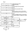
- FC handling When the "High-rotation/high-vehicle speed FC handling" is completed as described above, reverting to Fig. 4, in a step S5, when the engine output approaches a predetermined upper limit output, an "Output restriction fuel cut (FC) handling" for restricting the fuel injection of the upstream and downstream injection valves is executed.
- FC Output restriction fuel cut
- Fig. 9 is a flowchart showing a procedure of the "Output restriction FC handling", and is mainly executed by the injection quantity restriction unit 1042.
- a step S501 the present speed reducing ratio NEV is compared with a lower limit speed reducing ratio NEVref1, and if NEV ⁇ NEVref1, the sequence will proceed to a step S502.
- the present speed reducing ratio NEV is compared with an upper limit speed reducing ratio NEVrefh, and if NEV > NEVrefh, the sequence will proceed to a step S503.
- the present engine speed NE is compared with a predetermined upstream injection cut second number of revolutions NEuppfc2 (fixed value), and if NE ⁇ NEuppfc2, in a step S504, an upstream injection cut second flag Fuppfc2 is set (injection prohibited).
- the sequence will proceed to a step S511, and the upstream injection cut second flag Fuppfc2 is reset (injection permitted).
- a step S505 the engine speed NE is compared with a predetermined downstream injection cut second number of revolutions NElowfc2 (fixed value) , and if NE ⁇ NElowfc2, the sequence will proceed to a step S506 in order to cut also the downstream injection. Since the upstream injection cut second number of revolutions NEuppfc2 and the downstream injection cut second number of revolutions NElowfc2 have a relationship of NEuppfc2 ⁇ NElowfc2, even in this case, the upstream fuel injection valve 8a is always to be injection-cut prior to the downstream fuel injection valve 8b.
- a step S506 the engine load is discriminated, and if any other than non-load, the sequence will proceed to a step S507.
- a thinned-out frequency table (not shown) is referred to on the basis of the engine speed NE, and optimum thinned-out frequency of the downstream injection responsive to the engine speed NE is retrieved.
- a step S508 it is discriminated whether or not injection timing at this time is thinned-out timing, and if thinned-out timing, in a step S509, the downstream injection cut second flag Flowfc2 is set (injection prohibited). If any other than the thinned-out timing, in a step S510, the second flag Flowfc2 is reset (injection permitted).
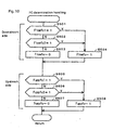
- FC determination handling for determining presence or absence of fuel injection cut on the upstream and downstream sides is executed on the basis of the handling results of each FC handling in the steps S4, S5.
- Fig. 10 is a flowchart showing a procedure of the "FC determination handling", and in a step S601, the downstream injection cut first flag Flowfc1 is referred to, and if this has been reset, further in a step S602, the downstream injection cut second flag Flowfc2 is referred to. If this has also been reset, in a step S603, the downstream injection cut flag Flowfc is reset (injection permitted). In the steps S601, S602, if at least one of the first flag Flowfc1 and the second flag Flowfc2 has been set, in a step S604, the downstream injection cut flag Flowfc is set (injection prohibited).
- a step S605 the upstream injection cut first flag Fuppfc1 is referred to, and if this has been reset, further in a step S606, the upstream injection cut second flag Fuppfc2 is referred to. If this has also been reset, in a step S507, the upstream injection cut flag Fuppfc is reset (injection permitted).
- the upstream injection cut flag Fuppfc is set (injection prohibited).
- the downstream injection cut flag Flowfc is referred to, and if this is in a reset state (injection permitted), in the step S8, the injection quantity Qlower of the downstream injection valve is calculated by adding, to a product of the total injection quantity Qtotal, the downstream injection rate (1 - Rupper) and the total correction factor Ktotal obtained by calculating by the correction factor calculation unit 103, a predetermined accelerated increase quantity value Tacc obtained by further calculating by the accelerated increase in quantity correction unit 1041 and invalid injection time TiVB.
- the accelerated correction quantity Tacc is calculated as a function of a rate of change of, for example, the throttle opening ⁇ TH and the manifold air pressure PB.
- the invalid injection time TiVB is a time period during which of the intake-valve opening time, complete injection of fuel is not involved, and is determined by type and structure of the fuel injection valve.
- the injection quantity Qlower is set to "0". That is, the injection on the downstream side is prohibited.
- a step S10 the upstream injection cut flag Fuppfc is referred to, and if this is in a reset state (injection permitted), in a step S11, the injection quantity Qupper of the upstream injection valve is calculated by further adding, to a product of the total injection quantity Qtotal, the upstream injection rate Rupper and the total correction factor Ktotal obtained by calculating by the correction factor calculation unit 103, invalid injection time TiVB.
- the injection quantity Qupper is set to "0" . That is, the injection on the upstream side is prohibited.
- the total inj ection quantity determination unit 101 determines total quantity Qtotal of fuel to be injected from each fuel injection valve 8a, 8b of the upstream and downstream sides.
- the injection rate determination unit 102 determines an injection rate Rupper of the upstream injection valve 8a.
- the injection quantity restriction unit 1042 restricts fuel injection due to each of the fuel injection valves 8a, 8b when process values such as the vehicle speed and the engine speed reach or approach a predetermined upper limit value.
- the injection quantity determination unit 105 determines the injection quantity Qupper of the upstream injection valve 8a and the injection quantity Qlower of the downstream injection valve 8b.
Landscapes
- Engineering & Computer Science (AREA)
- Chemical & Material Sciences (AREA)
- Combustion & Propulsion (AREA)
- Mechanical Engineering (AREA)
- General Engineering & Computer Science (AREA)
- Electrical Control Of Air Or Fuel Supplied To Internal-Combustion Engine (AREA)
- Combined Controls Of Internal Combustion Engines (AREA)
Abstract
Description
Claims (3)
- A fuel injection system for an internal combustion engine (20), having: an intake pipe equipped with a throttle valve (28); an upstream fuel injection valve (8a) provided upstream from said throttle valve (28); and a downstream fuel injection valve (8b) provided downstream from said throttle valve (28), comprising:means (2, 3, 4, 5, 6) for detecting a process value representing an operating state or a traveling state of an internal combustion engine (20); andmeans (1042) for restricting fuel injection due to each of said fuel injection valves (8a, 8b) when said process value reaches a predetermined upper limit value, characterized in thatsaid upstream fuel injection valve (8a) and said downstream fuel injection valve (8b) differ in an upper limit value at which said fuel injection is restricted.
- A fuel injection system for an internal combustion engine (20), having: an intake pipe equipped with a throttle valve (28); an upstream fuel injection valve (8a) provided upstream from said throttle valve (28); and a downstream fuel injection valve (8b) provided downstream from said throttle valve (28), comprising:means (2, 3, 4, 5, 6) for detecting a process value representing an operating state or a traveling state of an internal combustion engine (20); means (2, 3, 4, 5, 6) for detecting whether or not said process value reaches a quasi-upper limit value at this side of a predetermined upper limit value;means (1042) for restricting, when said process value reaches said quasi-upper limit value, fuel injection due to said upstream fuel injection valve (8a); andmeans (1042) for restricting, when said process value reaches said upper limit value, fuel injection due to said downstream fuel injection valve (8b).
- The fuel injection system for an internal combustion engine according to claim 1 or 2, characterized in that said means (1042) for restricting said fuel injection stops fuel due to said upstream fuel injection valve (8a) and causes said downstream fuel injection valve (8b) to perform a thinned-out injection.
Applications Claiming Priority (2)
| Application Number | Priority Date | Filing Date | Title |
|---|---|---|---|
| JP2002264173 | 2002-09-10 | ||
| JP2002264173A JP2004100587A (en) | 2002-09-10 | 2002-09-10 | Fuel injection device for internal combustion engine |
Publications (3)
| Publication Number | Publication Date |
|---|---|
| EP1398478A2 true EP1398478A2 (en) | 2004-03-17 |
| EP1398478A3 EP1398478A3 (en) | 2005-03-30 |
| EP1398478B1 EP1398478B1 (en) | 2006-09-06 |
Family
ID=31884746
Family Applications (1)
| Application Number | Title | Priority Date | Filing Date |
|---|---|---|---|
| EP03018845A Expired - Lifetime EP1398478B1 (en) | 2002-09-10 | 2003-08-19 | Fuel injection system for internal combustion engine |
Country Status (9)
| Country | Link |
|---|---|
| US (1) | US6832596B2 (en) |
| EP (1) | EP1398478B1 (en) |
| JP (1) | JP2004100587A (en) |
| CN (1) | CN1311152C (en) |
| BR (1) | BR0303415A (en) |
| CA (1) | CA2436968C (en) |
| DE (1) | DE60308120T2 (en) |
| ES (1) | ES2271443T3 (en) |
| MX (1) | MXPA03007557A (en) |
Families Citing this family (4)
| Publication number | Priority date | Publication date | Assignee | Title |
|---|---|---|---|---|
| JP2006283585A (en) * | 2005-03-31 | 2006-10-19 | Yamaha Motor Co Ltd | Throttle body |
| JP2007023908A (en) * | 2005-07-19 | 2007-02-01 | Nikki Co Ltd | Fuel supply control method and apparatus for internal combustion engine |
| JP4534914B2 (en) * | 2005-09-01 | 2010-09-01 | トヨタ自動車株式会社 | Fuel injection control device for internal combustion engine |
| CN103032188B (en) * | 2012-12-18 | 2016-04-06 | 潍柴动力股份有限公司 | A kind of controlling method of oil injection quantity in case of sudden increase of torque of engine and equipment |
Family Cites Families (14)
| Publication number | Priority date | Publication date | Assignee | Title |
|---|---|---|---|---|
| DE2800433A1 (en) * | 1978-01-05 | 1979-07-19 | Bosch Gmbh Robert | DEVICE FOR LIMITING THE SPEED OF A COMBUSTION ENGINE |
| US4768486A (en) * | 1986-12-05 | 1988-09-06 | Honda Giken Kogyo Kabushiki Kaisha | Fuel supply control system for internal combustion engine |
| US4819604A (en) * | 1986-12-10 | 1989-04-11 | Honda Giken Kogyo Kabushiki Kaisha | Fuel supply control method for internal combustion engines |
| JPH06102999B2 (en) * | 1986-12-10 | 1994-12-14 | 本田技研工業株式会社 | Fuel supply control method for internal combustion engine |
| JP2580191B2 (en) * | 1987-09-08 | 1997-02-12 | 本田技研工業株式会社 | Fuel supply control device for internal combustion engine |
| JPH04183949A (en) * | 1990-11-19 | 1992-06-30 | Mazda Motor Corp | Engine fuel control device |
| JP2937472B2 (en) * | 1990-11-30 | 1999-08-23 | マツダ株式会社 | Engine torque control device |
| JPH07166906A (en) * | 1993-12-14 | 1995-06-27 | Nissan Motor Co Ltd | Acceleration slip control device by fuel cut and ignition timing change |
| AUPM632494A0 (en) * | 1994-06-21 | 1994-07-14 | Biocom Pty Ltd | Auxiliary injector |
| JPH08232814A (en) * | 1995-02-28 | 1996-09-10 | Suzuki Motor Corp | Fuel injection device for internal combustion engine |
| JP3886193B2 (en) | 1997-01-14 | 2007-02-28 | 本田技研工業株式会社 | Fuel injection device |
| JP3913864B2 (en) * | 1997-10-27 | 2007-05-09 | 三菱電機株式会社 | In-cylinder injection fuel control system for internal combustion engine |
| US6467465B1 (en) * | 2001-01-10 | 2002-10-22 | Anthony R. Lorts | Throttle body fuel injector adapter manifold |
| US6508233B1 (en) * | 2001-04-04 | 2003-01-21 | Brunswick Corporation | Method for controlling a fuel system of a multiple injection system |
-
2002
- 2002-09-10 JP JP2002264173A patent/JP2004100587A/en active Pending
-
2003
- 2003-08-11 CA CA002436968A patent/CA2436968C/en not_active Expired - Fee Related
- 2003-08-19 DE DE60308120T patent/DE60308120T2/en not_active Expired - Fee Related
- 2003-08-19 EP EP03018845A patent/EP1398478B1/en not_active Expired - Lifetime
- 2003-08-19 ES ES03018845T patent/ES2271443T3/en not_active Expired - Lifetime
- 2003-08-21 CN CNB031539742A patent/CN1311152C/en not_active Expired - Fee Related
- 2003-08-21 BR BR0303415-1A patent/BR0303415A/en not_active IP Right Cessation
- 2003-08-22 MX MXPA03007557A patent/MXPA03007557A/en active IP Right Grant
- 2003-08-22 US US10/645,496 patent/US6832596B2/en not_active Expired - Fee Related
Also Published As
| Publication number | Publication date |
|---|---|
| CA2436968A1 (en) | 2004-03-10 |
| ES2271443T3 (en) | 2007-04-16 |
| CN1311152C (en) | 2007-04-18 |
| MXPA03007557A (en) | 2004-03-15 |
| DE60308120T2 (en) | 2006-12-21 |
| EP1398478B1 (en) | 2006-09-06 |
| CA2436968C (en) | 2006-05-16 |
| JP2004100587A (en) | 2004-04-02 |
| US20040045534A1 (en) | 2004-03-11 |
| CN1490511A (en) | 2004-04-21 |
| EP1398478A3 (en) | 2005-03-30 |
| US6832596B2 (en) | 2004-12-21 |
| BR0303415A (en) | 2004-09-08 |
| DE60308120D1 (en) | 2006-10-19 |
Similar Documents
| Publication | Publication Date | Title |
|---|---|---|
| EP1881192B1 (en) | Internal combustion engine provided with double system of fuel injection | |
| US20100042308A1 (en) | Fuel injection amount control apparatus of internal combustion engine | |
| KR0127127B1 (en) | Control device of engine | |
| US4836174A (en) | Engine control system | |
| JP3976322B2 (en) | Engine control device | |
| US5669347A (en) | Intake system for an internal combustion engine | |
| EP1398481B1 (en) | Fuel injection system for internal combustion engine | |
| EP1396633B1 (en) | Fuel injection system for internal combustion engine | |
| EP1398478B1 (en) | Fuel injection system for internal combustion engine | |
| EP0447765B1 (en) | An air-fuel ratio control device for an engine | |
| JP4711087B2 (en) | Intake control device for internal combustion engine | |
| EP1398480B1 (en) | Fuel injection control system for internal combustion engine | |
| JP4170773B2 (en) | Fuel injection timing control device for in-cylinder injection type engine | |
| EP1396628B1 (en) | Fuel injection system for internal combustion engine | |
| US20020117147A1 (en) | Ignition timing control apparatus for internal combustion engine | |
| JPH02201056A (en) | Fuel injection control device of internal combustion engine | |
| JPS62101868A (en) | Intake device of engine | |
| JPS63124865A (en) | Ignition timing control device for internal combustion engine | |
| JPH01159439A (en) | Internal combustion engine controller | |
| JPH02104934A (en) | Fuel injection device for engine | |
| JP2003013772A (en) | Swirl switching type fuel injection device |
Legal Events
| Date | Code | Title | Description |
|---|---|---|---|
| PUAI | Public reference made under article 153(3) epc to a published international application that has entered the european phase |
Free format text: ORIGINAL CODE: 0009012 |
|
| AK | Designated contracting states |
Kind code of ref document: A2 Designated state(s): AT BE BG CH CY CZ DE DK EE ES FI FR GB GR HU IE IT LI LU MC NL PT RO SE SI SK TR |
|
| AX | Request for extension of the european patent |
Extension state: AL LT LV MK |
|
| PUAL | Search report despatched |
Free format text: ORIGINAL CODE: 0009013 |
|
| AK | Designated contracting states |
Kind code of ref document: A3 Designated state(s): AT BE BG CH CY CZ DE DK EE ES FI FR GB GR HU IE IT LI LU MC NL PT RO SE SI SK TR |
|
| AX | Request for extension of the european patent |
Extension state: AL LT LV MK |
|
| 17P | Request for examination filed |
Effective date: 20050426 |
|
| 17Q | First examination report despatched |
Effective date: 20050530 |
|
| AKX | Designation fees paid |
Designated state(s): DE ES FR GB IT |
|
| GRAP | Despatch of communication of intention to grant a patent |
Free format text: ORIGINAL CODE: EPIDOSNIGR1 |
|
| GRAS | Grant fee paid |
Free format text: ORIGINAL CODE: EPIDOSNIGR3 |
|
| GRAA | (expected) grant |
Free format text: ORIGINAL CODE: 0009210 |
|
| AK | Designated contracting states |
Kind code of ref document: B1 Designated state(s): DE ES FR GB IT |
|
| PG25 | Lapsed in a contracting state [announced via postgrant information from national office to epo] |
Ref country code: IT Free format text: LAPSE BECAUSE OF FAILURE TO SUBMIT A TRANSLATION OF THE DESCRIPTION OR TO PAY THE FEE WITHIN THE PRESCRIBED TIME-LIMIT;WARNING: LAPSES OF ITALIAN PATENTS WITH EFFECTIVE DATE BEFORE 2007 MAY HAVE OCCURRED AT ANY TIME BEFORE 2007. THE CORRECT EFFECTIVE DATE MAY BE DIFFERENT FROM THE ONE RECORDED. Effective date: 20060906 |
|
| REG | Reference to a national code |
Ref country code: GB Ref legal event code: FG4D |
|
| REF | Corresponds to: |
Ref document number: 60308120 Country of ref document: DE Date of ref document: 20061019 Kind code of ref document: P |
|
| ET | Fr: translation filed | ||
| REG | Reference to a national code |
Ref country code: ES Ref legal event code: FG2A Ref document number: 2271443 Country of ref document: ES Kind code of ref document: T3 |
|
| PLBE | No opposition filed within time limit |
Free format text: ORIGINAL CODE: 0009261 |
|
| STAA | Information on the status of an ep patent application or granted ep patent |
Free format text: STATUS: NO OPPOSITION FILED WITHIN TIME LIMIT |
|
| 26N | No opposition filed |
Effective date: 20070607 |
|
| PGFP | Annual fee paid to national office [announced via postgrant information from national office to epo] |
Ref country code: DE Payment date: 20070928 Year of fee payment: 5 |
|
| PGFP | Annual fee paid to national office [announced via postgrant information from national office to epo] |
Ref country code: FR Payment date: 20071016 Year of fee payment: 5 |
|
| REG | Reference to a national code |
Ref country code: FR Ref legal event code: ST Effective date: 20090430 |
|
| PG25 | Lapsed in a contracting state [announced via postgrant information from national office to epo] |
Ref country code: FR Free format text: LAPSE BECAUSE OF NON-PAYMENT OF DUE FEES Effective date: 20080901 Ref country code: DE Free format text: LAPSE BECAUSE OF NON-PAYMENT OF DUE FEES Effective date: 20090303 |
|
| PGFP | Annual fee paid to national office [announced via postgrant information from national office to epo] |
Ref country code: ES Payment date: 20100915 Year of fee payment: 8 |
|
| PGFP | Annual fee paid to national office [announced via postgrant information from national office to epo] |
Ref country code: IT Payment date: 20100819 Year of fee payment: 8 |
|
| PGFP | Annual fee paid to national office [announced via postgrant information from national office to epo] |
Ref country code: GB Payment date: 20100818 Year of fee payment: 8 |
|
| GBPC | Gb: european patent ceased through non-payment of renewal fee |
Effective date: 20110819 |
|
| PG25 | Lapsed in a contracting state [announced via postgrant information from national office to epo] |
Ref country code: IT Free format text: LAPSE BECAUSE OF NON-PAYMENT OF DUE FEES Effective date: 20110819 |
|
| PG25 | Lapsed in a contracting state [announced via postgrant information from national office to epo] |
Ref country code: GB Free format text: LAPSE BECAUSE OF NON-PAYMENT OF DUE FEES Effective date: 20110819 |
|
| REG | Reference to a national code |
Ref country code: ES Ref legal event code: FD2A Effective date: 20130606 |
|
| PG25 | Lapsed in a contracting state [announced via postgrant information from national office to epo] |
Ref country code: ES Free format text: LAPSE BECAUSE OF NON-PAYMENT OF DUE FEES Effective date: 20110820 |