EP1398159A1 - Preventing crease formation in donor web in dye transfer printer - Google Patents
Preventing crease formation in donor web in dye transfer printer Download PDFInfo
- Publication number
- EP1398159A1 EP1398159A1 EP20030077741 EP03077741A EP1398159A1 EP 1398159 A1 EP1398159 A1 EP 1398159A1 EP 20030077741 EP20030077741 EP 20030077741 EP 03077741 A EP03077741 A EP 03077741A EP 1398159 A1 EP1398159 A1 EP 1398159A1
- Authority
- EP
- European Patent Office
- Prior art keywords
- dye transfer
- areas
- edge areas
- web
- printer
- Prior art date
- Legal status (The legal status is an assumption and is not a legal conclusion. Google has not performed a legal analysis and makes no representation as to the accuracy of the status listed.)
- Withdrawn
Links
Images




Classifications
-
- B—PERFORMING OPERATIONS; TRANSPORTING
- B41—PRINTING; LINING MACHINES; TYPEWRITERS; STAMPS
- B41J—TYPEWRITERS; SELECTIVE PRINTING MECHANISMS, i.e. MECHANISMS PRINTING OTHERWISE THAN FROM A FORME; CORRECTION OF TYPOGRAPHICAL ERRORS
- B41J2/00—Typewriters or selective printing mechanisms characterised by the printing or marking process for which they are designed
- B41J2/315—Typewriters or selective printing mechanisms characterised by the printing or marking process for which they are designed characterised by selective application of heat to a heat sensitive printing or impression-transfer material
- B41J2/32—Typewriters or selective printing mechanisms characterised by the printing or marking process for which they are designed characterised by selective application of heat to a heat sensitive printing or impression-transfer material using thermal heads
- B41J2/325—Typewriters or selective printing mechanisms characterised by the printing or marking process for which they are designed characterised by selective application of heat to a heat sensitive printing or impression-transfer material using thermal heads by selective transfer of ink from ink carrier, e.g. from ink ribbon or sheet
-
- B—PERFORMING OPERATIONS; TRANSPORTING
- B41—PRINTING; LINING MACHINES; TYPEWRITERS; STAMPS
- B41J—TYPEWRITERS; SELECTIVE PRINTING MECHANISMS, i.e. MECHANISMS PRINTING OTHERWISE THAN FROM A FORME; CORRECTION OF TYPOGRAPHICAL ERRORS
- B41J17/00—Mechanisms for manipulating page-width impression-transfer material, e.g. carbon paper
- B41J17/30—Constructions of guides for the impression-transfer material
-
- B—PERFORMING OPERATIONS; TRANSPORTING
- B41—PRINTING; LINING MACHINES; TYPEWRITERS; STAMPS
- B41J—TYPEWRITERS; SELECTIVE PRINTING MECHANISMS, i.e. MECHANISMS PRINTING OTHERWISE THAN FROM A FORME; CORRECTION OF TYPOGRAPHICAL ERRORS
- B41J35/00—Other apparatus or arrangements associated with, or incorporated in, ink-ribbon mechanisms
- B41J35/04—Ink-ribbon guides
Definitions
- the invention relates generally to dye transfer printers such as thermal printers, and in particular to the problem of crease formation in the dye transfer area of a donor web used in the printer. Crease formation in the dye transfer area can result in an undesirable line artifact being printed on a dye receiver.
- a typical multi-color donor web that is used in a thermal printer is substantially thin and has a repeating series of three different color sections or patches such as a yellow color section, a magenta color section and a cyan color section. Also, there may be a transparent laminating section after the cyan color section.
- Each color section of the donor web consists of a dye transfer area that is used for dye transfer printing and pair of longitudinal edge areas alongside the transfer area which are not used for printing.
- the dye transfer area is about 95% of the web width and the two edge areas are each about 2.5% of the web width.
- the various color dyes in the dye transfer areas of a single series of yellow, magenta and cyan color sections on a donor web are successively heat-transferred by a print head onto a dye receiver such as paper or transparency sheet or roll.
- the dye transfer from each transfer area to the dye receiver is done line-by-line widthwise across the transfer area via a bead of selectively heated resistive elements on the print head.
- the print head makes line contact across the entire width of the color section, but it only heats the dye transfer area, i.e. it does not heat the two edge areas alongside the dye transfer area.
- the donor web is subjected to a longitudinal tension between a donor supply spool and a donor take-up spool which are rearward and forward of the print head.
- the longitudinal tension coupled with the heat from the print head, causes a used color section to be stretched lengthwise at least from the print head to the donor take-up spool. Since the dye transfer area in a used color section has been heated by the print head, but the two edge areas alongside the transfer area have not been heated, the transfer area tends to be stretched more than the edge areas. As a result, the transfer area becomes thinner than the two edge areas and develops a wave-like or ripple distortion widthwise between the edge areas.
- the wave-like or ripple distortion in the transfer area causes one or more creases to form at least in a short trailing or rear end portion of the transfer area that has not been used for dye transfer.
- the creases tend to spread rearward from the trailing or rear end portion of the used transfer area into a leading or front end portion of an unused transfer area in the next (fresh) color section being advanced to the print head.
- the creases appear to be created because of the difference in thickness between the used transfer area and the edge areas as they are wound under tension from the print head and onto the donor take-up spool.
- the edge areas wrap differently on the spool than does the used transfer area because of the difference in thickness between the transfer area and the edge areas.
- the convolution build-up of the thicker edge areas on the spool becomes significantly greater than the convolution build-up of the thinner transfer areas.
- This non-uniform winding of the used color section increases the likelihood of one or more creases being created because the convolution build-up of the thicker edge areas on the donor take-up spool adds to the tension and distortion of the used transfer areas.
- a problem that can result is that a crease in the leading or front end portion of the unused transfer area of the next (fresh) color section will cause an undesirable line artifact to be printed on a leading or front end portion of the dye receiver when the print head is applied to the crease.
- the line artifact printed on the receiver is about 0.5 inches in length.
- the question presented therefore is how to solve the problem of the creases being created in the unused transfer area of each fresh color section so that no line artifacts are printed on the dye receiver.
- a dye transfer printer in which a donor web having successive dye transfer areas and opposite longitudinal edge areas alongside each one of the dye transfer areas is subjected to a longitudinal tension, when the donor web is advanced in the printer, that can stretch the dye transfer areas more than the edge areas because the dye transfer areas, but not the edge areas, are heated at a print head, is characterized in that:
- the edge areas can be weakened, for example, by perforating or piercing them to create holes in them, or by slitting or cutting them to create cuts in them.
- edge areas alongside a dye transfer area being used are stretched substantially the same as the dye transfer area, the likelihood of any creases being created in the next unused transfer area is substantially reduced. Thus, no line artifacts will be printed on a dye receiver in the printer.
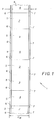
- FIG. 1 depicts a typical multi-color donor web or ribbon 1 that is used in a thermal color-printer.
- the donor web 1 is substantially thin and has a repeating series (only two shown) of three different color sections or patches such as a yellow color section 2, a magenta color section 3 and a cyan color section 4. Also, there may be a transparent laminating section (not shown) after the cyan color section 4.
- Each one of the successive color sections 2-4 of the donor web 1 consists of a dye transfer area 5 that is used for dye transfer printing and pair of longitudinal edge areas 6 and 7 alongside the transfer area which are not used for printing.
- the dye transfer area 5 is about 95% of the web width W and the two edge areas 6 and 7 are each about 2.5% of the web width.
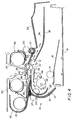
- FIGS. 2-6 depict operation of a known prior art thermal color-printer 10.
- a dye receiver sheet 12 e.g. paper or transparency
- a dye receiver sheet 12 is initially advanced forward via coaxial pick rollers 14 (only one shown) off a floating platen 16 in a tray 18 and into a channel 19 defined by a pair of curved longitudinal guides 20 and 22.
- a trailing (rear) edge sensor 24 midway in the channel 19 senses a trailing or rear edge 26 of the receiver sheet 12, it activates at least one of pair of parallel axis urge rollers 27, 27 in the channel 19.
- the activated rollers 27, 27 advance the receiver sheet 12 forward through the nip of a capstan roller 28 and a pinch roller 30, positioned beyond the channel 19, and to a leading (front) edge sensor 32.
- the leading edge sensor 32 has sensed a leading or front edge 34 of the dye receiver sheet 12 and activated the capstan roller 28 to cause that roller and the pinch roller 30 to advance the receiver sheet forward onto an intermediate tray 36.
- the receiver sheet 12 is advanced forward into the intermediate tray 36 so that the trailing or rear edge 26 of the receiver sheet can be moved beyond a hinged exit door 38 which is a longitudinal extension of the curved guide 20.
- the hinged exit door 38 closes and the capstan and pinch rollers 28 and 30 are reversed to advance the receiver sheet 12 rearward, i.e. rear edge 26 first, partially into a rewind chamber 40.
- the various color dyes in the dye transfer areas 5 of a single series of the color sections 2, 3 and 4 on the donor web 1 must be successively heat-transferred onto the dye receiver sheet 12. This is shown in FIGS. 4 and 5.
- a platen roller 42 is shifted via a rotated cam 44 and a platen lift 46 to adjacent a thermal print head 48.
- This causes the dye receiver sheet 12 and a first one of the successive color sections 2, 3, and 4 of the donor web 1 to be locally held together between the platen roller 42 and the print head 48.
- the capstan and pinch rollers 28 and 30 are reversed to again advance the dye receiver sheet 12 forward to begin to return the receiver sheet to the intermediate tray 36.
- the donor web 1 is advanced forward under a longitudinal tension, from a donor supply spool 50, over a first stationary (fixed) web guide 51, the print head 48 and a second stationary (fixed) web guide or guide nose 52, and then onto a donor take-up spool 54.
- the donor supply and take-up spools 50 and 54 together with the donor web 1 are provided in a replaceable cartridge 55 that is loaded into the printer 10.
- the color dye in the dye transfer area 5 of that color section is heat-transferred onto the dye receiver sheet 12.
- the dye transfer from the transfer area 5 to the receiver sheet 12 is done line-by-line widthwise across the transfer area via a bead of selectively heated resistive elements (not shown) on the print head 48.
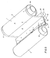
- the print head 48 makes line contact across the entire width W of the first color section 2 as depicted in FIG. 5 (the guide nose 52 and the dye receiver sheet 12 are not shown). However, the print head 48 only heats the dye transfer area 5, i.e. it does not heat two edge areas 6 and 7 alongside the transfer area.
- the platen roller 42 is shifted via the rotated cam 44 and the platen lift 46 from adjacent the print head 48 to separate the platen roller from the print head. This is shown in FIG. 3.
- capstan and pinch rollers 28 and 30 are reversed to advance the dye receiver sheet 12 rearward, i.e. trailing or rear edge 26 first, partially into the rewind chamber 40 and the used color section 2 is wrapped about the donor take-up spool 54. See FIG. 3.
- the dye transfer to the dye receiver sheet 12 is completed.
- the platen roller 42 is shifted via the rotated cam 44 and the platen lift 46 from adjacent the print head 48 to separate the platen roller from the print head, the capstan and pinch rollers 28 and 30 are reversed to advance the receiver sheet 12 rearward, i.e. trailing or rear edge 26 first, partially into the rewind chamber 40, and the last color section 4 is wrapped about the donor take-up spool 54.
- the platen roller 42 remains separated from the print head 48 and the capstan and pinch rollers 28 and 30 are reversed to again advance the dye receiver sheet 12 forward.
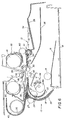
- a diverter 56 is pivoted to divert the receiver sheet 12 to an exit tray 58 instead of returning the receiver sheet to the intermediate tray 36 as in FIG. 4.
- a pair of parallel axis exit rollers 60 and 62 aid in advancing the receiver sheet 12 into the exit tray 58.
- the wave-like or ripple distortion 62 in the transfer area causes one or more creases 64 to be formed at least in a short trailing or rear end portion 66 of the transfer area that has not been used for dye transfer. See FIG. 8.
- the creases 64 tend to spread rearward from the trailing or rear end portion 66 of the used transfer area 5 into a leading or front end portion 68 of an unused transfer area 5 in the next (fresh) color section 2, 3 or 4 being advanced to the print head 48.
- the creases 64 appear to be created because of the difference in thickness between the used transfer area 5 and the edge areas 6 and 7 as they are wound under tension from the print head 48, over the guide nose 42, and onto the donor take-up spool 54.
- a problem that can result is that a crease 64 in the leading or front end portion 68 of the unused transfer area 5 of the next (fresh) color section 2, 3 or 4 will cause an undesirable line artifact 70 to be printed on a leading or front end portion 72 of the dye receiver sheet 12 when the print head 48 is applied to the crease. See FIG. 10.
- the line artifact 70 printed on the dye receiver sheet 12 is about 0.5 inches in length.
- the question presented therefore is how to solve the problem of the creases 64 being created in the unused transfer area 5 of each fresh color section 2, 3 or 4 so that no line artifacts 70 are printed on the dye receiver sheet 12.
- FIG. 11 depicts non-fixed web guide 74 that is an improvement over the second fixed web guide 52 in the printer 10.
- the improved web guide 74 is intended to replace the second fixed web guide 52 in the printer 10.
- the improved web guide 74 is positioned to extend widthwise across the donor web 1 and serves as a web weakening applicator for the successive edge areas 6 and 7 of the donor web.
- the web guide 74 is a rotationally supported cylindrical roller 76 having a length L that is slightly greater than the width W of the donor web 1.
- a pair of identical web contacting portions 78 and 80 of the roller 76 each have a width X that is the same as the individual widths Y of the edge areas 6 and 7 of the donor web 1. See FIGS. 1 and 11.
- the web contacting portions 78 and 80 are similarly rotated in contact with the successive edge areas 6 and 7 of the donor web to continuously perforate or pierce each one of the edge areas before it is wrapped about the donor take-up spool 54. This weakens the resistance of the successive edge areas 6 and 7, relative to the successive dye transfer areas 2, 3 and 4, to being stretched so that the edge areas can be stretched substantially the same as the dye transfer areas.
- the web contacting portions 78 and 80 are illustrated as being diagonally knurled in order to perforate or pierce the successive edge areas 6 and 7 of the donor web 1 to weaken them. However, it will be appreciated by those of ordinary skill in the art that the web contacting portions 78 and 80, instead of being knurled to perforate or pierce the edge areas 6 and 7, can have small pointed projections, small sharp points, or other suitable means which perforate or pierce, or slit or cut the edge areas.
- FIG. 12 shows a web section of the donor web 1 including the dye transfer area 5 and the edge areas 6 and 7, depicting the edge areas perforated or pierced with holes 82 to weaken their resistance to being stretched.
- FIG. 13 shows the web section in FIG. 12, but depicting the edge areas 6 and 7 slit or cut with cuts 84 to weaken their resistance to being stretched.
- An intermediate portion 86 of the roller 76, between the web contacting portions 78 and 80 is smooth in comparison to the web contacting portions.
Landscapes
- Electronic Switches (AREA)
- Impression-Transfer Materials And Handling Thereof (AREA)
Abstract
In a dye transfer printer, a donor web having successive dye
transfer areas and opposite longitudinal edge areas alongside each one of the dye
transfer areas is subjected to a longitudinal tension when the donor web is
advanced in the printer. The longitudinal tension can stretch the dye transfer areas
more than the edge areas because the dye transfer areas, but not the edge areas, are
heated at a print head. According to the invention, the resistance of the edge areas
relative to the dye transfer areas, to being stretched, is weakened so that the edge
areas can be stretched substantially the same as the dye transfer areas. If the edge
areas alongside a dye transfer area being used are stretched substantially the same
as the dye transfer area, the likelihood of any creases being created in the next
unused transfer area is substantially reduced. Thus, no line artifacts will be
printed on a dye receiver during dye transfer in the printer.
Description
- The invention relates generally to dye transfer printers such as thermal printers, and in particular to the problem of crease formation in the dye transfer area of a donor web used in the printer. Crease formation in the dye transfer area can result in an undesirable line artifact being printed on a dye receiver.
- A typical multi-color donor web that is used in a thermal printer is substantially thin and has a repeating series of three different color sections or patches such as a yellow color section, a magenta color section and a cyan color section. Also, there may be a transparent laminating section after the cyan color section.
- Each color section of the donor web consists of a dye transfer area that is used for dye transfer printing and pair of longitudinal edge areas alongside the transfer area which are not used for printing. The dye transfer area is about 95% of the web width and the two edge areas are each about 2.5% of the web width.
- To make a print, the various color dyes in the dye transfer areas of a single series of yellow, magenta and cyan color sections on a donor web are successively heat-transferred by a print head onto a dye receiver such as paper or transparency sheet or roll. The dye transfer from each transfer area to the dye receiver is done line-by-line widthwise across the transfer area via a bead of selectively heated resistive elements on the print head. The print head makes line contact across the entire width of the color section, but it only heats the dye transfer area, i.e. it does not heat the two edge areas alongside the dye transfer area.
- As each color section is used for dye transfer at the print head, the donor web is subjected to a longitudinal tension between a donor supply spool and a donor take-up spool which are rearward and forward of the print head. The longitudinal tension, coupled with the heat from the print head, causes a used color section to be stretched lengthwise at least from the print head to the donor take-up spool. Since the dye transfer area in a used color section has been heated by the print head, but the two edge areas alongside the transfer area have not been heated, the transfer area tends to be stretched more than the edge areas. As a result, the transfer area becomes thinner than the two edge areas and develops a wave-like or ripple distortion widthwise between the edge areas.
- After the last line is transferred from a dye transfer area to a dye receiver, and as the used color section is advanced forward from the print head and onto the donor take-up spool, the wave-like or ripple distortion in the transfer area causes one or more creases to form at least in a short trailing or rear end portion of the transfer area that has not been used for dye transfer. The creases tend to spread rearward from the trailing or rear end portion of the used transfer area into a leading or front end portion of an unused transfer area in the next (fresh) color section being advanced to the print head. The creases appear to be created because of the difference in thickness between the used transfer area and the edge areas as they are wound under tension from the print head and onto the donor take-up spool.
- When a used color section is wrapped under tension around the donor take-up spool, the edge areas wrap differently on the spool than does the used transfer area because of the difference in thickness between the transfer area and the edge areas. As each additional color section is wrapped around the donor take-up spool, the convolution build-up of the thicker edge areas on the spool becomes significantly greater than the convolution build-up of the thinner transfer areas. This non-uniform winding of the used color section increases the likelihood of one or more creases being created because the convolution build-up of the thicker edge areas on the donor take-up spool adds to the tension and distortion of the used transfer areas.
- A problem that can result is that a crease in the leading or front end portion of the unused transfer area of the next (fresh) color section will cause an undesirable line artifact to be printed on a leading or front end portion of the dye receiver when the print head is applied to the crease. The line artifact printed on the receiver is about 0.5 inches in length.
- The question presented therefore is how to solve the problem of the creases being created in the unused transfer area of each fresh color section so that no line artifacts are printed on the dye receiver.
- A dye transfer printer in which a donor web having successive dye transfer areas and opposite longitudinal edge areas alongside each one of the dye transfer areas is subjected to a longitudinal tension, when the donor web is advanced in the printer, that can stretch the dye transfer areas more than the edge areas because the dye transfer areas, but not the edge areas, are heated at a print head, is characterized in that:
- a web weakening applicator is positioned to weaken a resistance of the edge areas, relative to the dye transfer areas, to being stretched so that the edge areas can be stretched substantially the same as the dye transfer areas even though only the dye transfer areas are heated.
-
- The edge areas can be weakened, for example, by perforating or piercing them to create holes in them, or by slitting or cutting them to create cuts in them.
- If the edge areas alongside a dye transfer area being used are stretched substantially the same as the dye transfer area, the likelihood of any creases being created in the next unused transfer area is substantially reduced. Thus, no line artifacts will be printed on a dye receiver in the printer.
- FIG. 1 is plan view of a donor web including successive dye transfer areas and opposite edge areas alongside each one of the dye transfer areas;
- FIG. 2 is an elevation section view, partly in section, of a dye transfer printer, showing a beginning cycle during a printer operation;
- FIGS. 3 and 4 are elevation section views of the dye transfer printer as in FIG. 2, showing other cycles during the printer operation;
- FIG. 5 is perspective view of a printing or dye transfer station in the dye transfer printer;
- FIG. 6 is an elevation section view of the dye transfer printer as in FIG. 2, showing a final cycle during the printer operation;
- FIG. 7 is a cross section view of the donor web when the dye transfer area has been stretched thinner than the two edge areas alongside the dye transfer area, showing a wave-like or ripple distortion widthwise between the edge areas;
- FIG. 8 is a plan view of the donor web, showing creases spreading rearward from a trailing or rear end portion of a used transfer area into a leading or front end portion of an unused transfer area in the next (fresh) color section;
- FIG. 9 is a cross-section view of a prior art donor take-up spool in the dye transfer printer;
- FIG. 10 is a plan view of a dye receiver sheet, showing line artifacts printed on a leading or front edge portion of the receiver sheet;
- FIG. 11 is a perspective view of an improved web guide (or web weakening applicator) to be used in the dye transfer printer in place of an existing web guide in the printer, which according to a preferred embodiment of the invention weakens a resistance of the edge areas, relative to the dye transfer areas, to being stretched so that the edge areas can be stretched substantially the same as the dye transfer areas;
- FIG. 12 is a plan view of a web section of the donor web including a dye transfer area and opposite edge areas alongside the dye transfer area, showing the two edge areas perforated to weaken their resistance to being stretched; and
- FIG. 13 is a plan view of the web section in FIG. 12, but showing the two edge areas slit or cut to weaken their resistance to being stretched.
-
- FIG. 1 depicts a typical multi-color donor web or ribbon 1 that is used in a thermal color-printer. The donor web 1 is substantially thin and has a repeating series (only two shown) of three different color sections or patches such as a
yellow color section 2, amagenta color section 3 and acyan color section 4. Also, there may be a transparent laminating section (not shown) after thecyan color section 4. - Each one of the successive color sections 2-4 of the donor web 1 consists of a
dye transfer area 5 that is used for dye transfer printing and pair oflongitudinal edge areas dye transfer area 5 is about 95% of the web width W and the twoedge areas - FIGS. 2-6 depict operation of a known prior art thermal color-
printer 10. - Beginning with FIG. 2, a
dye receiver sheet 12, e.g. paper or transparency, is initially advanced forward via coaxial pick rollers 14 (only one shown) off afloating platen 16 in atray 18 and into achannel 19 defined by a pair of curvedlongitudinal guides edge sensor 24 midway in thechannel 19 senses a trailing orrear edge 26 of thereceiver sheet 12, it activates at least one of pair of parallelaxis urge rollers channel 19. The activatedrollers receiver sheet 12 forward through the nip of acapstan roller 28 and apinch roller 30, positioned beyond thechannel 19, and to a leading (front)edge sensor 32. - In FIG. 3, the leading
edge sensor 32 has sensed a leading orfront edge 34 of thedye receiver sheet 12 and activated thecapstan roller 28 to cause that roller and thepinch roller 30 to advance the receiver sheet forward onto anintermediate tray 36. Thereceiver sheet 12 is advanced forward into theintermediate tray 36 so that the trailing orrear edge 26 of the receiver sheet can be moved beyond ahinged exit door 38 which is a longitudinal extension of thecurved guide 20. Then, as illustrated, the hingedexit door 38 closes and the capstan andpinch rollers receiver sheet 12 rearward, i.e.rear edge 26 first, partially into arewind chamber 40. - To make a print, the various color dyes in the
dye transfer areas 5 of a single series of thecolor sections dye receiver sheet 12. This is shown in FIGS. 4 and 5. - In FIG. 4, a
platen roller 42 is shifted via a rotatedcam 44 and aplaten lift 46 to adjacent athermal print head 48. This causes thedye receiver sheet 12 and a first one of thesuccessive color sections platen roller 42 and theprint head 48. The capstan andpinch rollers dye receiver sheet 12 forward to begin to return the receiver sheet to theintermediate tray 36. At the same time, the donor web 1 is advanced forward under a longitudinal tension, from adonor supply spool 50, over a first stationary (fixed)web guide 51, theprint head 48 and a second stationary (fixed) web guide orguide nose 52, and then onto a donor take-up spool 54. The donor supply and take-up spools replaceable cartridge 55 that is loaded into theprinter 10. - When the first one of the
successive color sections print head 48 in FIG. 4, the color dye in thedye transfer area 5 of that color section is heat-transferred onto thedye receiver sheet 12. The dye transfer from thetransfer area 5 to thereceiver sheet 12 is done line-by-line widthwise across the transfer area via a bead of selectively heated resistive elements (not shown) on theprint head 48. Theprint head 48 makes line contact across the entire width W of thefirst color section 2 as depicted in FIG. 5 (theguide nose 52 and thedye receiver sheet 12 are not shown). However, theprint head 48 only heats thedye transfer area 5, i.e. it does not heat twoedge areas - As the
first color section 2 is used for dye transfer line-by-line, it moves from theprint head 48 and over theguide nose 52 in FIGS. 4 and 5. Then, once the dye transfer for thefirst color section 2 is completed, theplaten roller 42 is shifted via the rotatedcam 44 and theplaten lift 46 from adjacent theprint head 48 to separate the platen roller from the print head. This is shown in FIG. 3. - Then, the capstan and
pinch rollers dye receiver sheet 12 rearward, i.e. trailing orrear edge 26 first, partially into therewind chamber 40 and the usedcolor section 2 is wrapped about the donor take-upspool 54. See FIG. 3. - Then, the cycle in FIG. 4 is repeated with the next (fresh) one of the
successive color sections - Once the last one of the
successive color sections dye receiver sheet 12 is completed. Then, in FIG. 3, theplaten roller 42 is shifted via the rotatedcam 44 and theplaten lift 46 from adjacent theprint head 48 to separate the platen roller from the print head, the capstan andpinch rollers receiver sheet 12 rearward, i.e. trailing orrear edge 26 first, partially into therewind chamber 40, and thelast color section 4 is wrapped about the donor take-upspool 54. - Finally, as shown in FIG. 6, the
platen roller 42 remains separated from theprint head 48 and the capstan andpinch rollers dye receiver sheet 12 forward. However, in this instance adiverter 56 is pivoted to divert thereceiver sheet 12 to anexit tray 58 instead of returning the receiver sheet to theintermediate tray 36 as in FIG. 4. A pair of parallelaxis exit rollers receiver sheet 12 into theexit tray 58. - As each one in a single series of the
color sections print head 48 in FIGS. 4 and 5, it is stretched lengthwise under tension, particularly over the second stationary (fixed) web guide or guidenose 52. Since thedye transfer area 5 in a usedcolor section print head 48, but the twoedge areas dye transfer area 5 becomes thinner than the two edge areas and develops a wave-like or rippledistortion 62 widthwise between the edge areas. This is shown in FIG. 7. - After the last line is transferred from a
dye transfer area 5 to thedye receiver sheet 12, and as the usedcolor section print head 48, over theguide nose 52, and onto the donor take-upspool 54, the wave-like or rippledistortion 62 in the transfer area causes one ormore creases 64 to be formed at least in a short trailing orrear end portion 66 of the transfer area that has not been used for dye transfer. See FIG. 8. Thecreases 64 tend to spread rearward from the trailing orrear end portion 66 of the usedtransfer area 5 into a leading or front end portion 68 of anunused transfer area 5 in the next (fresh)color section print head 48. Thecreases 64 appear to be created because of the difference in thickness between the usedtransfer area 5 and theedge areas print head 48, over theguide nose 42, and onto the donor take-upspool 54. - When a used
color section spool 54, the twoedge areas transfer area 5 because of the difference in thickness between the transfer area and the edge areas. See FIGS. 7 and 9. As eachadditional color section spool 54, the convolution build-up of thethicker edge areas thinner transfer areas 5. See FIG. 9. This non-uniform winding of the used color section increases the likelihood of one or more of thecreases 64, shown in FIG. 8, being created because the convolution build-up of thethicker edge areas spool 54 adds to the tension and distortion of the usedtransfer areas 5. - A problem that can result is that a
crease 64 in the leading or front end portion 68 of theunused transfer area 5 of the next (fresh)color section undesirable line artifact 70 to be printed on a leading orfront end portion 72 of thedye receiver sheet 12 when theprint head 48 is applied to the crease. See FIG. 10. Theline artifact 70 printed on thedye receiver sheet 12 is about 0.5 inches in length. - The question presented therefore is how to solve the problem of the
creases 64 being created in theunused transfer area 5 of eachfresh color section line artifacts 70 are printed on thedye receiver sheet 12. - It has been determined that the likelihood of the wave-like or ripple
distortion 62 developing across the donor web 1 in the dye transfer printer 10 (as shown in FIG. 7) when the donor web 1 is advanced under tension from thedonor supply spool 50, over the first fixedweb guide 51, theprint head 48 and the second fixedweb guide 52, and onto the donor take-upspool 54 can be significantly reduced. This is done by weakening a resistance of thesuccessive edge areas dye transfer areas print head 48. If the wave-like or rippledistortion 62 is prevented from developing across the donor web 1, it is unlikely that any of thecreases 64 will be formed in the short trailing orrear end portion 66 of thetransfer area 5 that has not been used for dye transfer as shown in FIG. 8. Thus, the possibility of aline artifact 70 being printed on the dye receiver sheet 1 can be substantially eliminated. - FIG. 11 depicts
non-fixed web guide 74 that is an improvement over the second fixedweb guide 52 in theprinter 10. Theimproved web guide 74 is intended to replace the second fixedweb guide 52 in theprinter 10. - The
improved web guide 74 is positioned to extend widthwise across the donor web 1 and serves as a web weakening applicator for thesuccessive edge areas web guide 74 is a rotationally supportedcylindrical roller 76 having a length L that is slightly greater than the width W of the donor web 1. A pair of identicalweb contacting portions roller 76 each have a width X that is the same as the individual widths Y of theedge areas - When the donor web 1 is advanced under tension over the
roller 76, theweb contacting portions successive edge areas spool 54. This weakens the resistance of thesuccessive edge areas dye transfer areas - The
web contacting portions successive edge areas web contacting portions edge areas dye transfer area 5 and theedge areas holes 82 to weaken their resistance to being stretched. And FIG. 13 shows the web section in FIG. 12, but depicting theedge areas cuts 84 to weaken their resistance to being stretched. - An intermediate portion 86 of the
roller 76, between theweb contacting portions
Claims (11)
- A dye transfer printer in which a donor web having successive dye transfer areas and opposite longitudinal edge areas alongside each one of the dye transfer areas is subjected to a longitudinal tension, when the donor web is advanced in said printer, that can stretch the dye transfer areas more than the edge areas because the dye transfer areas, but not the edge areas, are heated at a print head, is characterized in that:a web weakening applicator is positioned to weaken a resistance of the edge areas, relative to the dye transfer areas, to being stretched so that the edge areas can be stretched substantially the same as the dye transfer areas even though only the dye transfer areas are heated.
- A dye transfer printer as recited in claim 1, wherein said web weakening applicator is rotated in contact with the edge areas of the donor web to perforate or pierce the edge areas in order to weaken their resistance to being stretched as the donor web is advanced in said printer.
- A dye transfer printer as recited in claim 2, wherein said web weakening applicator has web contacting portions substantially the same width as the edge areas of the donor web and that are knurled to perforate or pierce the edge areas.
- A dye transfer printer as recited in claim 1, wherein said web weakening applicator is rotated in contact with the edge areas of the donor web to slit or cut the edge areas in order to weaken their resistance to being stretched as the donor web is advanced in said printer.
- A dye transfer printer in which a donor web having successive dye transfer areas and opposite longitudinal edge areas alongside each one of the dye transfer areas is subjected to a longitudinal tension, when the donor web is advanced in said printer, that can stretch the dye transfer areas more than the edge areas because the dye transfer areas and not the edge areas are heated at a print head, is characterized in that:a web guide is positioned to extend across the donor guide and is adapted to perforate or pierce the edge areas, but not the dye transfer areas, to weaken the edge areas sufficiently with respect to the dye transfer areas so that the edge areas can be stretched substantially the same as the dye transfer areas.
- A dye transfer printer as recited in claim 5, wherein said web guide has web perforating or piercing portions that are rotated in contact with the edge areas of the donor web as the donor web is advanced in said printer.
- A method of equalizing web-stretching in a dye transfer printer in which a donor web having successive dye transfer areas and opposite longitudinal edge areas alongside each one of the dye transfer areas is subjected to a longitudinal tension, when the donor web is advanced in the printer, that can stretch the dye transfer areas more than the edge areas because the dye transfer areas and not the edge areas are heated at a print head, said method comprising:weakening a resistance of the edge areas, relative to the dye transfer areas, to being stretched so that the edge areas can be stretched substantially the same as the dye transfer areas even though only the dye transfer areas are heated.
- A method as recited in claim 7, wherein the resistance of the edge areas of the donor web to being stretched is weakened by rotating a web weakening applicator in contact with the edge areas as the donor web is advanced in the printer.
- A method as recited in claim 7, wherein the resistance of the edge areas of the donor web to being stretched are weakened by perforating or piercing them.
- A method as recited in claim 7, wherein the resistance of the edge areas of the donor web to being stretched are weakened by slitting or cutting them.
- A dye transfer printer in which a donor web having successive dye transfer areas and opposite longitudinal edge areas alongside each one of the dye transfer areas is subjected to a longitudinal tension, when the donor web is advanced in said printer, that can stretch the dye transfer areas more than the edge areas because the dye transfer areas and not the edge areas are heated at a print head, is characterized in that:web weakening means weakens the edge areas, relative to the dye transfer areas, so that the edge areas can be stretched substantially the same as the dye transfer areas even though only the dye transfer areas are heated.
Applications Claiming Priority (2)
| Application Number | Priority Date | Filing Date | Title |
|---|---|---|---|
| US242262 | 1994-05-13 | ||
| US10/242,262 US6744456B2 (en) | 2002-09-12 | 2002-09-12 | Preventing crease formation in donor web in dye transfer printer that can cause line artifact on print |
Publications (1)
| Publication Number | Publication Date |
|---|---|
| EP1398159A1 true EP1398159A1 (en) | 2004-03-17 |
Family
ID=31887772
Family Applications (1)
| Application Number | Title | Priority Date | Filing Date |
|---|---|---|---|
| EP20030077741 Withdrawn EP1398159A1 (en) | 2002-09-12 | 2003-09-01 | Preventing crease formation in donor web in dye transfer printer |
Country Status (3)
| Country | Link |
|---|---|
| US (1) | US6744456B2 (en) |
| EP (1) | EP1398159A1 (en) |
| JP (1) | JP2004098680A (en) |
Families Citing this family (2)
| Publication number | Priority date | Publication date | Assignee | Title |
|---|---|---|---|---|
| US7862137B2 (en) * | 2004-09-30 | 2011-01-04 | Lexmark International, Inc. | Method and system for avoiding bottom of page printing artifacts |
| JP2012158033A (en) * | 2011-01-31 | 2012-08-23 | Dainippon Printing Co Ltd | Thermal transfer printer and transfer method |
Citations (1)
| Publication number | Priority date | Publication date | Assignee | Title |
|---|---|---|---|---|
| JPH08230262A (en) * | 1995-02-28 | 1996-09-10 | Mitsubishi Electric Corp | Thermal transfer recorder |
Family Cites Families (2)
| Publication number | Priority date | Publication date | Assignee | Title |
|---|---|---|---|---|
| JPS591274A (en) * | 1982-06-29 | 1984-01-06 | Toshiba Corp | Thermal transfer recording device |
| JP3348354B2 (en) * | 1992-05-25 | 2002-11-20 | ソニー株式会社 | Thermal transfer printer |
-
2002
- 2002-09-12 US US10/242,262 patent/US6744456B2/en not_active Expired - Fee Related
-
2003
- 2003-08-29 JP JP2003306208A patent/JP2004098680A/en active Pending
- 2003-09-01 EP EP20030077741 patent/EP1398159A1/en not_active Withdrawn
Patent Citations (1)
| Publication number | Priority date | Publication date | Assignee | Title |
|---|---|---|---|---|
| JPH08230262A (en) * | 1995-02-28 | 1996-09-10 | Mitsubishi Electric Corp | Thermal transfer recorder |
Non-Patent Citations (1)
| Title |
|---|
| PATENT ABSTRACTS OF JAPAN vol. 1997, no. 01 31 January 1997 (1997-01-31) * |
Also Published As
| Publication number | Publication date |
|---|---|
| US20040051775A1 (en) | 2004-03-18 |
| JP2004098680A (en) | 2004-04-02 |
| US6744456B2 (en) | 2004-06-01 |
Similar Documents
| Publication | Publication Date | Title |
|---|---|---|
| US6715949B1 (en) | Medium-handling in printer for donor and receiver mediums | |
| US5555011A (en) | Lamination of a protective layer over an image produced by a thermal printer | |
| US6727933B2 (en) | Preventing crease formation in donor web in dye transfer printer that can cause line artifact on print | |
| US6744456B2 (en) | Preventing crease formation in donor web in dye transfer printer that can cause line artifact on print | |
| US6781616B2 (en) | Preventing crease formation in donor web in dye transfer printer that can cause line artifact on print | |
| JP7001495B2 (en) | Printer | |
| US6977669B2 (en) | Preventing crease formation in donor web in dye transfer printer that can cause line artifact on print | |
| US6768503B1 (en) | Preventing crease formation in donor web in dye transfer printer that can cause line artifact on print | |
| US6724412B1 (en) | Preventing crease formation in donor web in dye transfer printer that can cause line artifact on print | |
| US6757003B1 (en) | Preventing crease formation in donor web in dye transfer printer that can cause line artifact on print | |
| US6859221B2 (en) | Preventing crease formation in donor web in dye transfer printer that can cause line artifact on print | |
| EP1398161B1 (en) | Preventing crease formation in a donor web in a dye transfer printer | |
| US20040183889A1 (en) | Preventing crease formation in donor web in dye transfer printer that can cause line artifact on print | |
| US6762783B1 (en) | Preventing crease formation in donor web in dye transfer printer that can cause line artifact on print | |
| US6697093B1 (en) | Preventing crease formation in donor web in dye transfer printer that can cause line artifact on print | |
| EP1398160B1 (en) | Preventing crease formation in a donor web in a dye transfer printer | |
| JP3494783B2 (en) | Thermal printing method and apparatus | |
| US6975343B2 (en) | Preventing crease formation in donor web in dye transfer printer that can cause line artifact on print | |
| US20250100301A1 (en) | Thermal transfer printing device with decal function | |
| JP7014342B2 (en) | Thermal transfer printing device | |
| US7081910B2 (en) | Preventing crease formation in donor web in dye transfer printer that can cause line artifact on print | |
| US5851076A (en) | Printer adapted to guide a dye donor therein and method therefor | |
| JPH0858183A (en) | Thermal transfer printer | |
| JPH02286375A (en) | Thermal transfer recording device |
Legal Events
| Date | Code | Title | Description |
|---|---|---|---|
| PUAI | Public reference made under article 153(3) epc to a published international application that has entered the european phase |
Free format text: ORIGINAL CODE: 0009012 |
|
| AK | Designated contracting states |
Kind code of ref document: A1 Designated state(s): AT BE BG CH CY CZ DE DK EE ES FI FR GB GR HU IE IT LI LU MC NL PT RO SE SI SK TR |
|
| AX | Request for extension of the european patent |
Extension state: AL LT LV MK |
|
| AKX | Designation fees paid | ||
| REG | Reference to a national code |
Ref country code: DE Ref legal event code: 8566 |
|
| STAA | Information on the status of an ep patent application or granted ep patent |
Free format text: STATUS: THE APPLICATION IS DEEMED TO BE WITHDRAWN |
|
| 18D | Application deemed to be withdrawn |
Effective date: 20040918 |