EP1398117A2 - Universal setting tool for adhesively bonded rebar and threaded rod anchors - Google Patents
Universal setting tool for adhesively bonded rebar and threaded rod anchors Download PDFInfo
- Publication number
- EP1398117A2 EP1398117A2 EP03292217A EP03292217A EP1398117A2 EP 1398117 A2 EP1398117 A2 EP 1398117A2 EP 03292217 A EP03292217 A EP 03292217A EP 03292217 A EP03292217 A EP 03292217A EP 1398117 A2 EP1398117 A2 EP 1398117A2
- Authority
- EP
- European Patent Office
- Prior art keywords
- collet housing
- coil spring
- bore
- spring member
- setting tool
- Prior art date
- Legal status (The legal status is an assumption and is not a legal conclusion. Google has not performed a legal analysis and makes no representation as to the accuracy of the status listed.)
- Granted
Links
Images

Classifications
-
- B—PERFORMING OPERATIONS; TRANSPORTING
- B25—HAND TOOLS; PORTABLE POWER-DRIVEN TOOLS; MANIPULATORS
- B25B—TOOLS OR BENCH DEVICES NOT OTHERWISE PROVIDED FOR, FOR FASTENING, CONNECTING, DISENGAGING, OR HOLDING
- B25B31/00—Hand tools for applying fasteners
-
- B—PERFORMING OPERATIONS; TRANSPORTING
- B25—HAND TOOLS; PORTABLE POWER-DRIVEN TOOLS; MANIPULATORS
- B25B—TOOLS OR BENCH DEVICES NOT OTHERWISE PROVIDED FOR, FOR FASTENING, CONNECTING, DISENGAGING, OR HOLDING
- B25B13/00—Spanners; Wrenches
- B25B13/48—Spanners; Wrenches for special purposes
- B25B13/50—Spanners; Wrenches for special purposes for operating on work of special profile, e.g. pipes
- B25B13/5008—Spanners; Wrenches for special purposes for operating on work of special profile, e.g. pipes for operating on pipes or cylindrical objects
-
- B—PERFORMING OPERATIONS; TRANSPORTING
- B25—HAND TOOLS; PORTABLE POWER-DRIVEN TOOLS; MANIPULATORS
- B25B—TOOLS OR BENCH DEVICES NOT OTHERWISE PROVIDED FOR, FOR FASTENING, CONNECTING, DISENGAGING, OR HOLDING
- B25B13/00—Spanners; Wrenches
- B25B13/48—Spanners; Wrenches for special purposes
- B25B13/50—Spanners; Wrenches for special purposes for operating on work of special profile, e.g. pipes
- B25B13/5008—Spanners; Wrenches for special purposes for operating on work of special profile, e.g. pipes for operating on pipes or cylindrical objects
- B25B13/5016—Spanners; Wrenches for special purposes for operating on work of special profile, e.g. pipes for operating on pipes or cylindrical objects by externally gripping the pipe
Definitions
- the present invention relates generally to tools, and more particularly to a new and improved universal setting tool which is especially adapted for use in connection with the insertion and fixation of different diameter rebars and threaded rods within, for example, blind bores formed within concrete, masonry, rock, and similar substrates or underlying substructures, wherein a suitable adhesive or other similar bonding material is disposed within the blind bores for fixedly securing the rebars and threaded rods therewithin when the adhesive bonding material cures and sets.
- Rebars and threaded rods, studs, or anchors are extensively utilized within, for example, the construction industry in order to mount various components upon concrete, masonry, rock, and similar substrates or underlying foundations.
- the substrate or underlying foundation is provided with a blind bore within which the rebar or threaded rod, stud, or anchor is to be fixedly secured by means of, for example, a suitable adhesive bonding material, which has been previously disposed within the bottom portion of the blind bore or hole, upon curing and setting of the adhesive material.
- exemplary threaded stud or anchor systems are disclosed within United States Patents 4,982,625 and 4,404,875.
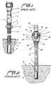
- FIGURE 1 which substantially corresponds to FIGURE 1 of the '875 patent, a blind bore 10 has been drilled within a concrete, masonry, rock, or similar foundation 14, and in order to fixedly secure a threaded stud 5 within the drilled bore 10, a capsule or ampule 8 containing adhesive resin materials is disposed within the bottom of the bore or hole 10.
- a drive unit 1 comprises an upper end portion 3 which is adapted to be mounted within a chuck mechanism 12 of a rotary drill, not shown, and a lower end portion 4 which is externally threaded in a manner similar to that of the threaded stud 5.
- An internally threaded nut member 6 is adapted to join the lower externally threaded end portion 4 of the drive unit 1 to the upper end portion of the threaded stud 5 as a result of the convexly shaped end portion 11 of the drive unit 1 being disposed in abutment with the upper planar end portion of the threaded stud 5.
- the threaded stud 5 When the threaded stud 5 is to be fixedly secured within the bore or hole 10 of the foundation or substrate 14, the lower chamfered or tapered end portion 7 of the threaded stud 5 is forced downwardly against the capsule or ampule 8 so as to fracture the same, and upon actuation of the drill tool, not shown, the threaded stud 5 is driven downwardly to the bottom end portion of the bore or hole 10 so as to not only be seated within the lowermost depth portion thereof but to also agitate and fully mix the adhesive resin materials or components together.
- the threaded stud or anchor system as disclosed within the aforenoted '625 patent, was developed so as to effectively overcome the various operational disadvantages or drawbacks characteristic of the anchor system disclosed within the aforenoted '875 patent and as disclosed within FIGURE 2, which corresponds substantially to FIGURE 1 of the '625 patent, a drilled hole 11 is formed within a concrete foundation member 10, and a breakable capsule 12, containing a suitable chemical adhesive material, is disposed within the bottom of the bore 11.
- An externally threaded stud or anchor 13 is adapted have its conically shaped or pointed lower end portion 14 inserted within the drilled bore 11, while the upper end portion of the threaded stud or anchor 13 is adapted to be disposed within a driver 18.
- the lower end portion of the driver 18 is provided with an internally threaded bore 26, and the axially inner end portion of the bore or hole 26 is undercut or radially enlarged as at 27, while the transversely extending end wall of the bore or hole 26 has an axially tapered face 28.
- An adaptor 30 is releasably attached to the upper end portion of the driver 18 by means of a transversely oriented retainer pin 38 and is provided for operatively connecting the driver 18 to a rotary drive means, such as, for example, an electric drill, not shown.
- the adaptor 30 comprises an upper shank portion 31 which is adapted to be disposed within the chuck portion of the drill, and a lower shaft portion 34 which is adapted to be seated within an axial bore 35 formed within the upper body portion 19 of the driver 18.
- the transversely extending pin 38 extends through a transverse bore 40 formed within the upper body portion 19 of the driver 18, as well as through a transverse bore 39 formed within the adaptor shaft portion 34, and is retained in position by means of an O-ring 41 disposed within a peripheral groove 42. It is noted that when the upper end portion of the threaded stud or anchor 13 is disposed within the internally threaded bore or hole portion 26 of the driver 18, the axially tapered face 28 comprising the transversely extending end wall, of the bore or hole 26 will be disposed in pressed contact with the convexly shaped upper end portion 15 of the threaded stud or anchor 13.
- Another object of the present invention is to provide a new and improved setting tool which is effectively universal in that the same can be used in connection with the insertion and fixation of both threaded rod and rebar type anchors within bores or holes which are pre-drilled within underlying substrates or foundations and which have suitable adhesive bonding materials disposed therein, whereby such new and improved setting tool effectively overcomes the various operational disadvantages or drawbacks characteristic of PRIOR ART setting tools.
- An additional object of the present invention is to provide a new and improved setting-tool which is effectively universal in that the same can be used in connection with the insertion and fixation of both threaded rod and rebar type anchors within bores or holes which are pre-drilled within underlying substrates or foundations and which have suitable adhesive bonding materials disposed therein, and wherein further, the setting tool can also be used in connection with the insertion and fixation of different rebar and threaded rod type anchors having different diametrical extents.
- a further object of the present invention is to provide a new and improved setting tool which is effectively universal in that the same can be used in connection with the insertion and fixation of both threaded rod and rebar type anchors within bores or holes which are pre-drilled within underlying substrates or foundations and which have suitable adhesive bonding materials disposed therein, and wherein further the setting tool can rapidly engage both the threaded rod and rebar type anchors so as to readily and quickly perform the insertion and fixation procedures.
- a last object of the present invention is to provide a new and improved setting tool which is effectively universal in that the same can be used in connection with the insertion and fixation of both threaded rod and rebar type anchors within bores or holes which are pre-drilled within underlying substrates or foundations and which have suitable adhesive bonding materials disposed therein, and wherein further the setting tool can be rapidly disengaged from both the threaded rod and rebar type anchors so as to readily and quickly complete the insertion and fixation procedures without adversely affecting or disturbing the disposition of the threaded rod or rebar type anchors within the adhesive bonding material disposed within the pre-drilled bores or holes defined within the underlying substrate or foundation.
- a new and improved setting tool which comprises a collet member which comprises a stub shaft portion at one end thereof for fixed disposition within a rotary chuck mechanism of a rotary drive tool, and an axially oriented stepped bore extends into the interior of the collet from the opposite end thereof.
- a coil spring is disposed within the stepped bore, and one end of the coil spring is staked or secured upon the collet.
- the coil spring effectively defines an axially oriented expansible and contractible tubular member into which a free end portion of a rebar or threaded rod anchor member can be inserted.
- both rebar and threaded rod anchor members are able to be drivingly inserted into the adhesive material disposed within the bores or holes pre-drilled within the underlying foundations or substrates, and in addition, different rebars or threaded rod anchor members, having different diametrical extents, can be driven by means of the setting tool of the present invention.
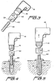
- the setting tool 110 comprises a substantially cylindrical collet housing 112 which has an axially extending stub shaft 114 integrally formed at, for example, upon a first upper end portion thereof, and it is to be appreciated that the stub shaft 114 is adapted to be inserted within a chuck mechanism 116 of a speed-controlled power tool 118, such as, for example, an electric drill.
- a speed-controlled power tool 118 such as, for example, an electric drill.
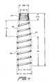
- the second opposite lower end portion of the collet housing 112 has a stepped cylindrical bore 120 defined therein, wherein the stepped bore 120 extends axially inwardly from a lower end surface 122 of the collet housing 112. More particularly, the stepped bore 120 is seen to comprise a first large-diameter bore portion 124 as defined by means of a first interior peripheral wall portion 126, and a second small-diameter bore portion or pocket 128 as defined by means of a second interior peripheral wall portion 130, wherein the stepped bore 120 is adapted to house or accommodate a coil spring member 132, the actual specifications or structural characteristics of which are more clearly appreciated from FIGURE 7 .
- the coil spring member 132 preferably has an overall length dimension L of approximately 10 cm, and accordingly, the axial extent or depth of the stepped bore 120 defined within the collet housing 112 has a substantially corresponding dimension so as to properly accommodate the coil spring member 132 therewithin as can best be appreciated from FIGURE 6 .
- the coil spring member 132 is seen to comprise a first lower straight, large diameter tubular section 134, a second upper-intermediate tapered diameter section 136, and a third uppermost small diameter section 138 comprising a plurality of axially compressed stacked spring coils.
- the first lower straight, large diameter tubular section 134 has an axial length dimension (SSL) of approximately 5,75 cm an outside diameter (LOD) dimension of approximately 2,7 cm, and an inside diameter (LID) dimension of approximately 2,25 cm, with the wire forming the coil spring member 132 having a thickness dimension or diameter of 0,25 cm.
- SSL axial length dimension
- LOD outside diameter
- LID inside diameter
- the second upper-intermediate tapered diameter section 136 has an axial length dimension (TSL) of approximately 3,2 cm, and it is noted that the pitch of the coil spring member 132, as defined between successive coils of the coil spring member 132 throughout both the first lower straight, larger diameter tubular section 134 and the second upper-intermediate tapered diameter section 136, is approximately 1,1 cm which is sufficiently large so as to permit any burrs present upon the rebar members to effectively self-thread through the coil spring member 132.
- TSL axial length dimension
- the third uppermost small diameter section 138 of the coil spring member 132 comprising the plurality of stacked spring coils has an axial length dimension (STKL) of approximately 1,3 cm and that the outside diameter (SOD) dimension of such spring section 138 is 1,75 cm while the inside diameter (SID) dimension of such spring section 138 is 1,3 cm.
- the lowermost end coil 142 of the coil spring member 132 projects outwardly from the stepped bore 120 and extends radially outwardly beyond the outer diametrical extent of the large diameter bore portion 124 so as to terminate at a terminal end portion 144.
- terminal end portion 144 of the coil spring member 132 is bent upwardly with respect to such lowermost end coil 142 at an angle of approximately 90° so as to be disposed substantially parallel to the longitudinal axis 140 of the collet housing 112.
- the upwardly bent terminal end portion 144 of the coil spring member 132 may have an axial length of approximately 2,6 cm and it is further appreciated that the lowermost end portion of the collet housing 112 is provided with a bore 146 which extends axially inwardly from the lower end surface portion 122 of the collet housing 112 so as to have a corresponding depth of approximately 2,6 cm for accommodating the terminal end portion 144 of the coil spring member 132.
- the lower end portion of the collet housing 122 is provided with a bore 148 which extends substantially radially inwardly from an outer peripheral surface portion of the collet housing 112 so as to intersect the axial bore 146.
- the bore 148 is internally threaded so as to operatively receive a suitable set screw 150 such that when the set screw 150 is fully threadedly engaged within the internally threaded bore 148, the inner terminal end of the set screw 150 will engage the bent terminal end portion 144 of the coil spring member 132 so as to fixedly secure the bent terminal end portion 144 of the coil spring member 132 within the axially extending bore 146.
- the set screw 150 not only prevents the bent terminal end portion 144 of the coil spring member 132 from becoming disengaged from the axially extending bore 146 by being axially with-drawn therefrom, but in addition, the set screw 150 also prevents any relative rotation of the bent terminal end portion 144 of the coil spring member 132 with respect to the axially extending bore 146. It is to be noted that while the bore 148 has been illustrated as being radially oriented, the bore 148 may alternatively be oriented in a chordwise manner with respect to axial bore 146.
- FIGURES 3-5 In order to fixedly secure a rebar or threaded rod anchor member within a particular substrate or foundation, a bore or hole 152 is pre-drilled within the substrate or foundation 154, and a suitable chemically activated adhesive material 156 is disposed within the pre-drilled bore or hole 152.
- the adhesive material 156 may comprise an adhesive material disposed in any one of several structural forms, such as, for example, the ampules or capsules as disclosed within the aforenoted ' 625 and '875 patents, the adhesive material may also be contained within a rope, slug, or stick as disclosed within the aforenoted '256 patent. In connection with the instance illustrated within FIGURES 4 and 5, the adhesive material is shown as being embodied within a rope, slug, or stick similar to that disclosed within the aforenoted '256 patent.
- the rebar or threaded rod anchor 158 is inserted into the large-diameter bore portion 124 and axially fed through such large-diameter bore portion 124 until the upper end portion 160 of the rebar or threaded rod anchor 158 encounters the upper end portion of the tapered diameter section 136 of the coil spring member 132, or the lower end portion of the stacked-coil small diameter section 138 of the coil spring member 132 such that frictional contact is effectively established between the upper end portion 160 of the rebar or threaded rod anchor 158 and the coil spring member 132.
- the rotary drive of the rotary power tool 118 is activated so as to slowly rotate the chuck mechanism 116 thereof, and accordingly the collet housing 112 fixedly secured within the chuck mechanism 116, in the clockwise direction CW.
- the upper end of the coil spring member 132 which comprises a right-handed spring, is effectively prevented from undergoing rotational movement with respect to the rebar or threaded rod anchor 158 as a result of the aforenoted frictional contact previously established between the upper end of the coil spring member 132 and the rebar or threaded rod anchor 158
- the bent terminal end portion 144 of the coil spring member 132 is fixedly secured within the axial bore 146 by means of the set screw 150 disposed within radial bore 148, the slow clockwise CW rotation of the chuck mechanism 116 and the collet housing 112 causes the coil spring member 132 to effectively be circumferentially wrapped around the rebar or threaded rod anchor 158 in
- the gripped rebar or threaded rod anchor 158 is now ready to be inserted into the adhesive material 156 previously disposed within the bore 152 formed within the substrate or foundation, as disclosed within FIG URE 4 , and upon relatively slow rotational drive of the chuck mechanism 116 in the clockwise direction CW, in conjunction with the axial feeding of the rebar or threaded rod anchor 158 into the adhesive material 156, the adhesive material 156 is stirred, mixed, and activated.
- the degree to which the coil spring member 132 is radially contracted is variable depending upon the diametrical extent of the rebar or threaded rod anchor 158 being gripped, hence, the universal nature or utility of the setting tool 110 of the present invention.
- the power tool 118, the chuck mechanism 116, and the collet member 112 are then able to fully removed from the upper end portion of the rebar or threaded rod anchor 158 which now projects outwardly from the underlying foundation or substrate 154, and the adhesive material 156 is then permitted to cure and set so as to in fact fixedly secure the rebar or threaded rod anchor 158 therewithin.
- a single, new and improved setting tool which can be readily used in connection with the adhesive bonding of both rebar and threaded rod anchors within pre-drilled holes or bores formed within an underlying substrate or foundation.
- the radially expansible and contractible coil spring member within the collet housing of the setting tool, the outer peripheral surface portions of both rebar and threaded rod anchor members are able to be tightly engaged for driving insertion into the adhesive material.
- the single setting tool can likewise be used to insert and fix rebar or threaded rod anchor members, having different diametrical extents or dimensions, within the pre-drilled, adhesive-filled holes or bores provided within the underlying foundations or substrates.
Landscapes
- Engineering & Computer Science (AREA)
- Mechanical Engineering (AREA)
- Joining Of Building Structures In Genera (AREA)
- Hand Tools For Fitting Together And Separating, Or Other Hand Tools (AREA)
- Dowels (AREA)
Abstract
Description
and as disclosed within FIGURE 2, which corresponds substantially to FIGURE 1 of the '625 patent, a drilled hole 11 is formed within a
Claims (11)
- A universal setting tool for use in connection with the insertion and fixation of different anchors within bores (152) preformed within a substrate (154), comprising:a collet housing (112) defining an axis (140) around which said collet housing is capable of being rotated;a shaft (114) integrally fixed upon a first end of said collet housing for insertion within a chuck mechanism (116) of a rotary drive tool (118) such that when said shaft is fixedly secured within the chuck mechanism of the rotary tool, and the chuck mechanism of the rotary tool is rotated, said collet housing will be rotated around said axis;a first bore (120) extending axially inwardly from a second end of said collet housing; andradially expansible and contractible means (132) disposed within said first bore (120) of said collet housing (112) for radially contracting within said first bore of said collet housing when said collet housing is rotated in a first direction around said axis so as to be capable of fixedly gripping an anchor (158) inserted into said first bore of said collet housing, and for radially expanding within said first bore of said collet housing when said collet housing is rotated in a second opposite direction around said axis so as to be capable of releasing an anchor previously inserted into said first bore of said collet housing and fixedly gripped by said radially expansible and contractible means as a result of said radially expansible and contractible means having been radially contracted in response to said collet housing (112) having been rotated in said first direction.
- The setting tool as set forth in Claim 1, wherein:the degree to which said radially expansible and contractible means (132) is radially contractible is variable so as to be render said setting tool capable of gripping different anchors having different diametrical extents.
- The setting tool as set forth in one of Claims 1 and 2, wherein:said radially expansible and contractible means comprises a coil spring member (132).
- The setting tool as set forth in Claim 3, wherein said coil spring member (132) comprises :a small diameter portion (138) disposed at an axially inner portion (130) of said first bore (120) of said collet housing (112) for frictionally engaging an axially inner end portion (160) of an anchor (158) inserted into said first bore (120) of said collet housing such that said small diameter portion (138) of said coil spring member is effectively rotationally restrained as a result of the frictional engagement with the axially inner end portion of the anchor; anda large diameter portion (134) disposed at an axially outer portion of said first bore of said collet housing for permitting the anchor to be axially inserted into said coil spring member (132) such that the axially inner end portion of the anchor can engage said small diameter portion (138) of said coil spring member.
- The setting tool as set forth in Claim 4,wherein:said large diameter portion (134) of said coil spring member comprises a terminal end portion (144) which is fixedly secured to said collet housing (112) so as to facilitate said radial contraction and expansion of said coil spring member as said collet housing is respectively rotated in said first and second directions around said axis.
- The setting tool as set forth in Claim 5, further comprising:a second axially extending bore (146) defined within said second end of said collet housing (112); andsaid terminal end portion (144) of said coil spring member (132) is disposed within said second axially extending bore defined within said second end of said collet housing.
- The setting tool as set forth in Claim 6, further comprising:a radially extending bore (148) defined within said second end of said collet housing (112) and intersecting said second axially extending bore (146) defined within said second end of said collet housing; anda set screw (150) threadedly engaged within said radially extending bore (148) for engaging said terminal end portion (144) of said coil spring member so as to fixedly retain said terminal end portion of said coil spring member within said second axially extending bore.
- The setting tool as set forth in one of Claims 4 to 7, wherein:said first axially extending bore defined within said collet housing (112) comprises a stepped configuration, comprising a small diameter portion (128) and a large diameter portion (126), for respectively accommodating said small (138) and large (132) diameter portions of said coil spring member.
- The setting tool as set forth in Claim 8, wherein:said small diameter portion (138) of said coil spring member (132) comprises a plurality of axially compressed stacked coils; andsaid small diameter portion of said stepped bore defines a pocket region (128) within which said plurality of axially compressed stacked coils are disposed.
- The setting tool as set forth in one of Claims 4 to 9, wherein said coil spring member (132) further comprises:a radially tapered section (136) interconnecting said small (138) and large (134) diameter portions of said coil spring member.
- In combination, a rotary tool, and a universal setting tool for use in connection with the insertion and fixation of different anchors within bores preformed within a substrate, comprising:a rotary tool (118);a chuck mechanism (116) operatively mounted within said rotary tool; anda universal setting tool as set forth in one of Claims 1 to 10.
Applications Claiming Priority (2)
| Application Number | Priority Date | Filing Date | Title |
|---|---|---|---|
| US238178 | 2002-09-10 | ||
| US10/238,178 US6598499B1 (en) | 2002-09-10 | 2002-09-10 | Universal setting tool for adhesively bonded rebar and threaded rod anchors |
Publications (3)
| Publication Number | Publication Date |
|---|---|
| EP1398117A2 true EP1398117A2 (en) | 2004-03-17 |
| EP1398117A3 EP1398117A3 (en) | 2008-11-26 |
| EP1398117B1 EP1398117B1 (en) | 2011-06-15 |
Family
ID=27613073
Family Applications (1)
| Application Number | Title | Priority Date | Filing Date |
|---|---|---|---|
| EP03292217A Expired - Lifetime EP1398117B1 (en) | 2002-09-10 | 2003-09-09 | Universal setting tool for adhesively bonded rebar and threaded rod anchors |
Country Status (7)
| Country | Link |
|---|---|
| US (1) | US6598499B1 (en) |
| EP (1) | EP1398117B1 (en) |
| AT (1) | ATE512766T1 (en) |
| AU (1) | AU2003244593B2 (en) |
| CA (1) | CA2439237C (en) |
| ES (1) | ES2367557T3 (en) |
| NZ (1) | NZ528102A (en) |
Cited By (2)
| Publication number | Priority date | Publication date | Assignee | Title |
|---|---|---|---|---|
| DE102006047673B4 (en) * | 2005-09-30 | 2015-04-30 | Adolf Würth GmbH & Co. KG | screwing |
| CN109853853A (en) * | 2019-02-15 | 2019-06-07 | 广东庆余堂建筑科技有限公司 | A kind of prestress wire anchor |
Families Citing this family (13)
| Publication number | Priority date | Publication date | Assignee | Title |
|---|---|---|---|---|
| US7095317B2 (en) * | 2002-01-18 | 2006-08-22 | Donald Albrecht | Brake early warning system and method of use |
| DK2959774T3 (en) | 2003-03-28 | 2019-05-13 | Inguran Llc | PROCEDURE FOR CRYCONSERVATION OF SEAT CELLS |
| US20060248987A1 (en) * | 2005-05-05 | 2006-11-09 | Patrick White | Ratchet handle |
| AT508218B1 (en) | 2009-04-22 | 2012-06-15 | Laner Richard Ing | HAND TOOL HOLDER |
| US8585335B2 (en) * | 2009-12-08 | 2013-11-19 | Alessandro Carbonelli | Anchor bolt installation system |
| US8544182B2 (en) * | 2010-09-29 | 2013-10-01 | Kck Inventions, Llc | Assembly for leveling new concrete and sub-grade |
| ITTV20130207A1 (en) * | 2013-12-13 | 2015-06-14 | Stefano Antonini | "KEY FOR THE REMOVAL OF FILTER OIL ENDOTHERMIC OIL CAPSULES" |
| EP3144466B1 (en) * | 2015-09-15 | 2018-04-18 | Sandvik Mining and Construction Oy | Arrangement in rock drilling machine and method of mounting rock drilling machine |
| CN109056720B (en) * | 2018-08-23 | 2023-05-30 | 厦门市金海明工贸有限公司 | Deep hole recyclable anchor cable bearing plate reinforcing device and method |
| CN113235938B (en) * | 2021-04-29 | 2022-12-09 | 中建三局科创产业发展有限公司 | Steel bar binding machine for construction site |
| CN113338356B (en) * | 2021-06-17 | 2026-02-06 | 中国水利水电第七工程局有限公司 | Anti-floating anchor rod construction structure and construction method thereof |
| US20240116207A1 (en) * | 2022-10-06 | 2024-04-11 | Simpson Strong-Tie Company Inc. | Sealant spreader device for use in preparing holes for glued-in-rod structures |
| CN115467693B (en) * | 2022-11-14 | 2023-08-18 | 中国矿业大学(北京) | Tunnel support stock/anchor rope resin cartridge anchored agitator |
Family Cites Families (32)
| Publication number | Priority date | Publication date | Assignee | Title |
|---|---|---|---|---|
| US1566691A (en) | 1925-12-22 | Stud-bolt tool | ||
| US958980A (en) | 1908-11-23 | 1910-05-24 | Charles E Chester | Chuck. |
| US1549041A (en) | 1924-09-17 | 1925-08-11 | William A Yeagher | Stud-removing tool |
| US2326317A (en) | 1939-11-22 | 1943-08-10 | Chieago Pneumatic Tool Company | Impact wrench |
| US2336157A (en) | 1942-04-04 | 1943-12-07 | Gen Motors Corp | Stud driver |
| US2622466A (en) | 1949-04-18 | 1952-12-23 | Vanden Bos | Stud remover and driver |
| US2800820A (en) | 1954-06-04 | 1957-07-30 | Groov Pin Corp | Driver tool for self tapping inserts, struds, screw bolts, and the like |
| US2933960A (en) | 1957-06-10 | 1960-04-26 | Studrive Inc | Stud driving chuck |
| US2959994A (en) * | 1958-12-12 | 1960-11-15 | Kile Brothers Mfg Company | Oil filter turning tool with coiled spring gripping member |
| US3269226A (en) * | 1963-12-04 | 1966-08-30 | Lisle Corp | Wrench |
| US3280666A (en) | 1964-03-20 | 1966-10-25 | Neuschotz Robert | Tools for installing threaded elements |
| US3244055A (en) | 1964-03-26 | 1966-04-05 | Schuermann Fritz | Detachable anchor bolts |
| US3292463A (en) | 1966-01-10 | 1966-12-20 | Titan Tool Co | Wrench adapter |
| US3368430A (en) | 1966-03-07 | 1968-02-13 | American Steel And Pump Corp | Stud driver and release tools |
| US3850055A (en) * | 1973-09-21 | 1974-11-26 | Expando Prod Co | Fastener tool |
| GB1601591A (en) * | 1978-05-31 | 1981-11-04 | Thackray C F Ltd | Screw extracting device |
| US4404875A (en) | 1980-07-18 | 1983-09-20 | Usm Corporation | Installer drive unit for chemical anchor |
| US4513643A (en) | 1982-03-24 | 1985-04-30 | Titan Tool Company | Automatic stud driving tool |
| US4536115A (en) * | 1982-06-30 | 1985-08-20 | Helderman J Frank | Anchor apparatus for insertion into a pre-formed hole |
| GB2152417B (en) * | 1984-01-10 | 1987-09-16 | Charles Wolstenhulme | Fastener and tool for fastening and unfastening the same |
| US4652193A (en) | 1986-02-03 | 1987-03-24 | Hibbs Jerry M | Adhesively secured anchor |
| US4982625A (en) * | 1986-11-10 | 1991-01-08 | A.T. & G. Company, Inc. | Adaptor and driver for an adhesive capsule anchor |
| US4872298A (en) | 1988-02-12 | 1989-10-10 | Klemic Jr Frank | Concrete anchor bolt setting device |
| US5315902A (en) * | 1992-11-24 | 1994-05-31 | Gripping Tools Technologies, Inc. | Stud removing tool |
| US5492039A (en) * | 1994-04-08 | 1996-02-20 | Harris Corporation | Threaded object driving tool and method |
| US5681135A (en) * | 1995-01-19 | 1997-10-28 | Simonson; Peter Melott | Threaded fastener with multi-stage torque limiting applicator |
| DE19704002A1 (en) | 1997-02-04 | 1998-08-06 | Hilti Ag | Anchor rod for composite anchors |
| DE19717498A1 (en) * | 1997-04-25 | 1998-10-29 | Hilti Ag | Setting tool for anchor rods of composite anchors |
| US6125726A (en) * | 1997-12-31 | 2000-10-03 | Emhart Inc. | Tool for attaching to an element for handling thereof |
| DE29912708U1 (en) * | 1999-07-16 | 2000-11-30 | Bickel, Günter, 98574 Asbach | Screwing tool for screwing in threaded bolts |
| US6367138B1 (en) * | 1999-09-15 | 2002-04-09 | Emhart Inc. | Power installation tool for helical coil inserts |
| US6416256B1 (en) | 2000-07-26 | 2002-07-09 | Illinois Tool Works Inc. | Method of making and applying chemical anchoring adhesive |
-
2002
- 2002-09-10 US US10/238,178 patent/US6598499B1/en not_active Expired - Fee Related
-
2003
- 2003-09-03 CA CA002439237A patent/CA2439237C/en not_active Expired - Lifetime
- 2003-09-08 AU AU2003244593A patent/AU2003244593B2/en not_active Expired
- 2003-09-09 ES ES03292217T patent/ES2367557T3/en not_active Expired - Lifetime
- 2003-09-09 AT AT03292217T patent/ATE512766T1/en not_active IP Right Cessation
- 2003-09-09 EP EP03292217A patent/EP1398117B1/en not_active Expired - Lifetime
- 2003-09-09 NZ NZ528102A patent/NZ528102A/en not_active IP Right Cessation
Cited By (2)
| Publication number | Priority date | Publication date | Assignee | Title |
|---|---|---|---|---|
| DE102006047673B4 (en) * | 2005-09-30 | 2015-04-30 | Adolf Würth GmbH & Co. KG | screwing |
| CN109853853A (en) * | 2019-02-15 | 2019-06-07 | 广东庆余堂建筑科技有限公司 | A kind of prestress wire anchor |
Also Published As
| Publication number | Publication date |
|---|---|
| CA2439237C (en) | 2008-11-18 |
| CA2439237A1 (en) | 2004-03-10 |
| NZ528102A (en) | 2004-05-28 |
| ATE512766T1 (en) | 2011-07-15 |
| ES2367557T3 (en) | 2011-11-04 |
| US6598499B1 (en) | 2003-07-29 |
| EP1398117B1 (en) | 2011-06-15 |
| AU2003244593B2 (en) | 2005-10-27 |
| EP1398117A3 (en) | 2008-11-26 |
| AU2003244593A1 (en) | 2004-03-25 |
Similar Documents
| Publication | Publication Date | Title |
|---|---|---|
| EP1398117B1 (en) | Universal setting tool for adhesively bonded rebar and threaded rod anchors | |
| US4556350A (en) | Mine roof anchor bolt | |
| US3772957A (en) | Self-drilling and sealing rivet | |
| US4907928A (en) | Fastening member for securement into hard materials | |
| US5168781A (en) | Drive socket | |
| US6012358A (en) | Setting tool for self-cutting undercut anchors | |
| US4386882A (en) | Self-drilling anchor dowel | |
| CN101251021B (en) | Tensioning assembly for a cable bolt | |
| US8070405B2 (en) | Self drilling bolt with anchor | |
| US7114902B2 (en) | Self-tapping bush-shaped screwed insert | |
| JP2006153277A (en) | Expanding anchor | |
| JP2016056571A (en) | Fixing structure of screw member, fixing method of screw member, and fixing strength management method of screw member | |
| EP1452277A2 (en) | Setting tool for adhesively bonded threaded rod anchors | |
| EP4308822B1 (en) | Method and levelling screw for installing an attachment part | |
| EP0273434A1 (en) | Driver for reinforcement bar chemical anchor | |
| JPS6236835B2 (en) | ||
| NZ272159A (en) | Anchor system has a female anchor set within a hole in masonry with a hardenable adhesive by an interengaging setting tool | |
| JPH0641816Y2 (en) | Anchor member driving jig | |
| EP4495347A1 (en) | Holder | |
| EP0525274A1 (en) | A holding device for receiving an externally threaded shaft or rod member | |
| JP3660082B2 (en) | Attachment for chemical anchor driving | |
| TWI598515B (en) | Screw having compound extrusion plunger and a method putting the screw into a drilling in a substrate | |
| GB2158187A (en) | Coupling device for transmitting rotation | |
| JPH0440859Y2 (en) | ||
| AU769505B2 (en) | A fastener |
Legal Events
| Date | Code | Title | Description |
|---|---|---|---|
| PUAI | Public reference made under article 153(3) epc to a published international application that has entered the european phase |
Free format text: ORIGINAL CODE: 0009012 |
|
| AK | Designated contracting states |
Kind code of ref document: A2 Designated state(s): AT BE BG CH CY CZ DE DK EE ES FI FR GB GR HU IE IT LI LU MC NL PT RO SE SI SK TR |
|
| AX | Request for extension of the european patent |
Extension state: AL LT LV MK |
|
| PUAL | Search report despatched |
Free format text: ORIGINAL CODE: 0009013 |
|
| AK | Designated contracting states |
Kind code of ref document: A3 Designated state(s): AT BE BG CH CY CZ DE DK EE ES FI FR GB GR HU IE IT LI LU MC NL PT RO SE SI SK TR |
|
| AX | Request for extension of the european patent |
Extension state: AL LT LV MK |
|
| 17P | Request for examination filed |
Effective date: 20090514 |
|
| AKX | Designation fees paid |
Designated state(s): AT BE BG CH CY CZ DE DK EE ES FI FR GB GR HU IE IT LI LU MC NL PT RO SE SI SK TR |
|
| 17Q | First examination report despatched |
Effective date: 20100610 |
|
| GRAP | Despatch of communication of intention to grant a patent |
Free format text: ORIGINAL CODE: EPIDOSNIGR1 |
|
| GRAS | Grant fee paid |
Free format text: ORIGINAL CODE: EPIDOSNIGR3 |
|
| GRAA | (expected) grant |
Free format text: ORIGINAL CODE: 0009210 |
|
| AK | Designated contracting states |
Kind code of ref document: B1 Designated state(s): AT BE BG CH CY CZ DE DK EE ES FI FR GB GR HU IE IT LI LU MC NL PT RO SE SI SK TR |
|
| REG | Reference to a national code |
Ref country code: GB Ref legal event code: FG4D Ref country code: CH Ref legal event code: EP |
|
| REG | Reference to a national code |
Ref country code: IE Ref legal event code: FG4D |
|
| REG | Reference to a national code |
Ref country code: DE Ref legal event code: R096 Ref document number: 60337393 Country of ref document: DE Effective date: 20110728 |
|
| REG | Reference to a national code |
Ref country code: NL Ref legal event code: VDEP Effective date: 20110615 |
|
| PG25 | Lapsed in a contracting state [announced via postgrant information from national office to epo] |
Ref country code: SE Free format text: LAPSE BECAUSE OF FAILURE TO SUBMIT A TRANSLATION OF THE DESCRIPTION OR TO PAY THE FEE WITHIN THE PRESCRIBED TIME-LIMIT Effective date: 20110615 |
|
| REG | Reference to a national code |
Ref country code: ES Ref legal event code: FG2A Ref document number: 2367557 Country of ref document: ES Kind code of ref document: T3 Effective date: 20111104 |
|
| PG25 | Lapsed in a contracting state [announced via postgrant information from national office to epo] |
Ref country code: AT Free format text: LAPSE BECAUSE OF FAILURE TO SUBMIT A TRANSLATION OF THE DESCRIPTION OR TO PAY THE FEE WITHIN THE PRESCRIBED TIME-LIMIT Effective date: 20110615 Ref country code: FI Free format text: LAPSE BECAUSE OF FAILURE TO SUBMIT A TRANSLATION OF THE DESCRIPTION OR TO PAY THE FEE WITHIN THE PRESCRIBED TIME-LIMIT Effective date: 20110615 Ref country code: SI Free format text: LAPSE BECAUSE OF FAILURE TO SUBMIT A TRANSLATION OF THE DESCRIPTION OR TO PAY THE FEE WITHIN THE PRESCRIBED TIME-LIMIT Effective date: 20110615 Ref country code: GR Free format text: LAPSE BECAUSE OF FAILURE TO SUBMIT A TRANSLATION OF THE DESCRIPTION OR TO PAY THE FEE WITHIN THE PRESCRIBED TIME-LIMIT Effective date: 20110916 Ref country code: CY Free format text: LAPSE BECAUSE OF FAILURE TO SUBMIT A TRANSLATION OF THE DESCRIPTION OR TO PAY THE FEE WITHIN THE PRESCRIBED TIME-LIMIT Effective date: 20110615 |
|
| PGFP | Annual fee paid to national office [announced via postgrant information from national office to epo] |
Ref country code: GB Payment date: 20110926 Year of fee payment: 9 Ref country code: ES Payment date: 20110926 Year of fee payment: 9 |
|
| PG25 | Lapsed in a contracting state [announced via postgrant information from national office to epo] |
Ref country code: NL Free format text: LAPSE BECAUSE OF FAILURE TO SUBMIT A TRANSLATION OF THE DESCRIPTION OR TO PAY THE FEE WITHIN THE PRESCRIBED TIME-LIMIT Effective date: 20110615 |
|
| PG25 | Lapsed in a contracting state [announced via postgrant information from national office to epo] |
Ref country code: EE Free format text: LAPSE BECAUSE OF FAILURE TO SUBMIT A TRANSLATION OF THE DESCRIPTION OR TO PAY THE FEE WITHIN THE PRESCRIBED TIME-LIMIT Effective date: 20110615 Ref country code: PT Free format text: LAPSE BECAUSE OF FAILURE TO SUBMIT A TRANSLATION OF THE DESCRIPTION OR TO PAY THE FEE WITHIN THE PRESCRIBED TIME-LIMIT Effective date: 20111017 Ref country code: CZ Free format text: LAPSE BECAUSE OF FAILURE TO SUBMIT A TRANSLATION OF THE DESCRIPTION OR TO PAY THE FEE WITHIN THE PRESCRIBED TIME-LIMIT Effective date: 20110615 |
|
| PG25 | Lapsed in a contracting state [announced via postgrant information from national office to epo] |
Ref country code: SK Free format text: LAPSE BECAUSE OF FAILURE TO SUBMIT A TRANSLATION OF THE DESCRIPTION OR TO PAY THE FEE WITHIN THE PRESCRIBED TIME-LIMIT Effective date: 20110615 Ref country code: RO Free format text: LAPSE BECAUSE OF FAILURE TO SUBMIT A TRANSLATION OF THE DESCRIPTION OR TO PAY THE FEE WITHIN THE PRESCRIBED TIME-LIMIT Effective date: 20110615 |
|
| PLBE | No opposition filed within time limit |
Free format text: ORIGINAL CODE: 0009261 |
|
| STAA | Information on the status of an ep patent application or granted ep patent |
Free format text: STATUS: NO OPPOSITION FILED WITHIN TIME LIMIT |
|
| PG25 | Lapsed in a contracting state [announced via postgrant information from national office to epo] |
Ref country code: MC Free format text: LAPSE BECAUSE OF NON-PAYMENT OF DUE FEES Effective date: 20110930 |
|
| REG | Reference to a national code |
Ref country code: CH Ref legal event code: PL |
|
| 26N | No opposition filed |
Effective date: 20120316 |
|
| REG | Reference to a national code |
Ref country code: IE Ref legal event code: MM4A |
|
| PG25 | Lapsed in a contracting state [announced via postgrant information from national office to epo] |
Ref country code: DK Free format text: LAPSE BECAUSE OF FAILURE TO SUBMIT A TRANSLATION OF THE DESCRIPTION OR TO PAY THE FEE WITHIN THE PRESCRIBED TIME-LIMIT Effective date: 20110615 |
|
| REG | Reference to a national code |
Ref country code: DE Ref legal event code: R097 Ref document number: 60337393 Country of ref document: DE Effective date: 20120316 |
|
| PG25 | Lapsed in a contracting state [announced via postgrant information from national office to epo] |
Ref country code: LI Free format text: LAPSE BECAUSE OF NON-PAYMENT OF DUE FEES Effective date: 20110930 Ref country code: IE Free format text: LAPSE BECAUSE OF NON-PAYMENT OF DUE FEES Effective date: 20110909 Ref country code: CH Free format text: LAPSE BECAUSE OF NON-PAYMENT OF DUE FEES Effective date: 20110930 |
|
| GBPC | Gb: european patent ceased through non-payment of renewal fee |
Effective date: 20120909 |
|
| PG25 | Lapsed in a contracting state [announced via postgrant information from national office to epo] |
Ref country code: LU Free format text: LAPSE BECAUSE OF NON-PAYMENT OF DUE FEES Effective date: 20110909 |
|
| PG25 | Lapsed in a contracting state [announced via postgrant information from national office to epo] |
Ref country code: BG Free format text: LAPSE BECAUSE OF FAILURE TO SUBMIT A TRANSLATION OF THE DESCRIPTION OR TO PAY THE FEE WITHIN THE PRESCRIBED TIME-LIMIT Effective date: 20110915 |
|
| REG | Reference to a national code |
Ref country code: DE Ref legal event code: R119 Ref document number: 60337393 Country of ref document: DE Effective date: 20130403 |
|
| PG25 | Lapsed in a contracting state [announced via postgrant information from national office to epo] |
Ref country code: DE Free format text: LAPSE BECAUSE OF NON-PAYMENT OF DUE FEES Effective date: 20130403 Ref country code: GB Free format text: LAPSE BECAUSE OF NON-PAYMENT OF DUE FEES Effective date: 20120909 |
|
| PG25 | Lapsed in a contracting state [announced via postgrant information from national office to epo] |
Ref country code: IT Free format text: LAPSE BECAUSE OF NON-PAYMENT OF DUE FEES Effective date: 20120909 |
|
| PG25 | Lapsed in a contracting state [announced via postgrant information from national office to epo] |
Ref country code: TR Free format text: LAPSE BECAUSE OF FAILURE TO SUBMIT A TRANSLATION OF THE DESCRIPTION OR TO PAY THE FEE WITHIN THE PRESCRIBED TIME-LIMIT Effective date: 20110615 |
|
| REG | Reference to a national code |
Ref country code: ES Ref legal event code: FD2A Effective date: 20131018 |
|
| PG25 | Lapsed in a contracting state [announced via postgrant information from national office to epo] |
Ref country code: ES Free format text: LAPSE BECAUSE OF NON-PAYMENT OF DUE FEES Effective date: 20120910 Ref country code: HU Free format text: LAPSE BECAUSE OF FAILURE TO SUBMIT A TRANSLATION OF THE DESCRIPTION OR TO PAY THE FEE WITHIN THE PRESCRIBED TIME-LIMIT Effective date: 20110615 |
|
| PGFP | Annual fee paid to national office [announced via postgrant information from national office to epo] |
Ref country code: FR Payment date: 20130919 Year of fee payment: 11 |
|
| PGFP | Annual fee paid to national office [announced via postgrant information from national office to epo] |
Ref country code: BE Payment date: 20130927 Year of fee payment: 11 |
|
| REG | Reference to a national code |
Ref country code: FR Ref legal event code: ST Effective date: 20150529 |
|
| PG25 | Lapsed in a contracting state [announced via postgrant information from national office to epo] |
Ref country code: BE Free format text: LAPSE BECAUSE OF NON-PAYMENT OF DUE FEES Effective date: 20140930 |
|
| PG25 | Lapsed in a contracting state [announced via postgrant information from national office to epo] |
Ref country code: FR Free format text: LAPSE BECAUSE OF NON-PAYMENT OF DUE FEES Effective date: 20140930 |