EP1398069B1 - Exhaust treatment device - Google Patents
Exhaust treatment device Download PDFInfo
- Publication number
- EP1398069B1 EP1398069B1 EP03077480A EP03077480A EP1398069B1 EP 1398069 B1 EP1398069 B1 EP 1398069B1 EP 03077480 A EP03077480 A EP 03077480A EP 03077480 A EP03077480 A EP 03077480A EP 1398069 B1 EP1398069 B1 EP 1398069B1
- Authority
- EP
- European Patent Office
- Prior art keywords
- treatment device
- exhaust treatment
- oxide
- filter elements
- washcoat
- Prior art date
- Legal status (The legal status is an assumption and is not a legal conclusion. Google has not performed a legal analysis and makes no representation as to the accuracy of the status listed.)
- Expired - Lifetime
Links
Images



Classifications
-
- F—MECHANICAL ENGINEERING; LIGHTING; HEATING; WEAPONS; BLASTING
- F01—MACHINES OR ENGINES IN GENERAL; ENGINE PLANTS IN GENERAL; STEAM ENGINES
- F01N—GAS-FLOW SILENCERS OR EXHAUST APPARATUS FOR MACHINES OR ENGINES IN GENERAL; GAS-FLOW SILENCERS OR EXHAUST APPARATUS FOR INTERNAL-COMBUSTION ENGINES
- F01N3/00—Exhaust or silencing apparatus having means for purifying, rendering innocuous, or otherwise treating exhaust
- F01N3/08—Exhaust or silencing apparatus having means for purifying, rendering innocuous, or otherwise treating exhaust for rendering innocuous
- F01N3/0807—Exhaust or silencing apparatus having means for purifying, rendering innocuous, or otherwise treating exhaust for rendering innocuous by using absorbents or adsorbents
- F01N3/0828—Exhaust or silencing apparatus having means for purifying, rendering innocuous, or otherwise treating exhaust for rendering innocuous by using absorbents or adsorbents characterised by the absorbed or adsorbed substances
- F01N3/0842—Nitrogen oxides
-
- B—PERFORMING OPERATIONS; TRANSPORTING
- B01—PHYSICAL OR CHEMICAL PROCESSES OR APPARATUS IN GENERAL
- B01D—SEPARATION
- B01D53/00—Separation of gases or vapours; Recovering vapours of volatile solvents from gases; Chemical or biological purification of waste gases, e.g. engine exhaust gases, smoke, fumes, flue gases, aerosols
- B01D53/34—Chemical or biological purification of waste gases
- B01D53/92—Chemical or biological purification of waste gases of engine exhaust gases
- B01D53/94—Chemical or biological purification of waste gases of engine exhaust gases by catalytic processes
- B01D53/944—Simultaneously removing carbon monoxide, hydrocarbons or carbon making use of oxidation catalysts
-
- F—MECHANICAL ENGINEERING; LIGHTING; HEATING; WEAPONS; BLASTING
- F01—MACHINES OR ENGINES IN GENERAL; ENGINE PLANTS IN GENERAL; STEAM ENGINES
- F01N—GAS-FLOW SILENCERS OR EXHAUST APPARATUS FOR MACHINES OR ENGINES IN GENERAL; GAS-FLOW SILENCERS OR EXHAUST APPARATUS FOR INTERNAL-COMBUSTION ENGINES
- F01N13/00—Exhaust or silencing apparatus characterised by constructional features
- F01N13/009—Exhaust or silencing apparatus characterised by constructional features having two or more separate purifying devices arranged in series
- F01N13/0097—Exhaust or silencing apparatus characterised by constructional features having two or more separate purifying devices arranged in series the purifying devices are arranged in a single housing
-
- F—MECHANICAL ENGINEERING; LIGHTING; HEATING; WEAPONS; BLASTING
- F01—MACHINES OR ENGINES IN GENERAL; ENGINE PLANTS IN GENERAL; STEAM ENGINES
- F01N—GAS-FLOW SILENCERS OR EXHAUST APPARATUS FOR MACHINES OR ENGINES IN GENERAL; GAS-FLOW SILENCERS OR EXHAUST APPARATUS FOR INTERNAL-COMBUSTION ENGINES
- F01N3/00—Exhaust or silencing apparatus having means for purifying, rendering innocuous, or otherwise treating exhaust
- F01N3/02—Exhaust or silencing apparatus having means for purifying, rendering innocuous, or otherwise treating exhaust for cooling, or for removing solid constituents of, exhaust
- F01N3/021—Exhaust or silencing apparatus having means for purifying, rendering innocuous, or otherwise treating exhaust for cooling, or for removing solid constituents of, exhaust by means of filters
- F01N3/023—Exhaust or silencing apparatus having means for purifying, rendering innocuous, or otherwise treating exhaust for cooling, or for removing solid constituents of, exhaust by means of filters using means for regenerating the filters, e.g. by burning trapped particles
- F01N3/0231—Exhaust or silencing apparatus having means for purifying, rendering innocuous, or otherwise treating exhaust for cooling, or for removing solid constituents of, exhaust by means of filters using means for regenerating the filters, e.g. by burning trapped particles using special exhaust apparatus upstream of the filter for producing nitrogen dioxide, e.g. for continuous filter regeneration systems [CRT]
-
- F—MECHANICAL ENGINEERING; LIGHTING; HEATING; WEAPONS; BLASTING
- F01—MACHINES OR ENGINES IN GENERAL; ENGINE PLANTS IN GENERAL; STEAM ENGINES
- F01N—GAS-FLOW SILENCERS OR EXHAUST APPARATUS FOR MACHINES OR ENGINES IN GENERAL; GAS-FLOW SILENCERS OR EXHAUST APPARATUS FOR INTERNAL-COMBUSTION ENGINES
- F01N3/00—Exhaust or silencing apparatus having means for purifying, rendering innocuous, or otherwise treating exhaust
- F01N3/02—Exhaust or silencing apparatus having means for purifying, rendering innocuous, or otherwise treating exhaust for cooling, or for removing solid constituents of, exhaust
- F01N3/021—Exhaust or silencing apparatus having means for purifying, rendering innocuous, or otherwise treating exhaust for cooling, or for removing solid constituents of, exhaust by means of filters
- F01N3/033—Exhaust or silencing apparatus having means for purifying, rendering innocuous, or otherwise treating exhaust for cooling, or for removing solid constituents of, exhaust by means of filters in combination with other devices
- F01N3/035—Exhaust or silencing apparatus having means for purifying, rendering innocuous, or otherwise treating exhaust for cooling, or for removing solid constituents of, exhaust by means of filters in combination with other devices with catalytic reactors
-
- F—MECHANICAL ENGINEERING; LIGHTING; HEATING; WEAPONS; BLASTING
- F01—MACHINES OR ENGINES IN GENERAL; ENGINE PLANTS IN GENERAL; STEAM ENGINES
- F01N—GAS-FLOW SILENCERS OR EXHAUST APPARATUS FOR MACHINES OR ENGINES IN GENERAL; GAS-FLOW SILENCERS OR EXHAUST APPARATUS FOR INTERNAL-COMBUSTION ENGINES
- F01N3/00—Exhaust or silencing apparatus having means for purifying, rendering innocuous, or otherwise treating exhaust
- F01N3/08—Exhaust or silencing apparatus having means for purifying, rendering innocuous, or otherwise treating exhaust for rendering innocuous
- F01N3/0807—Exhaust or silencing apparatus having means for purifying, rendering innocuous, or otherwise treating exhaust for rendering innocuous by using absorbents or adsorbents
- F01N3/0821—Exhaust or silencing apparatus having means for purifying, rendering innocuous, or otherwise treating exhaust for rendering innocuous by using absorbents or adsorbents combined with particulate filter
-
- B—PERFORMING OPERATIONS; TRANSPORTING
- B01—PHYSICAL OR CHEMICAL PROCESSES OR APPARATUS IN GENERAL
- B01D—SEPARATION
- B01D2255/00—Catalysts
- B01D2255/10—Noble metals or compounds thereof
- B01D2255/102—Platinum group metals
-
- B—PERFORMING OPERATIONS; TRANSPORTING
- B01—PHYSICAL OR CHEMICAL PROCESSES OR APPARATUS IN GENERAL
- B01D—SEPARATION
- B01D2255/00—Catalysts
- B01D2255/20—Metals or compounds thereof
- B01D2255/202—Alkali metals
-
- B—PERFORMING OPERATIONS; TRANSPORTING
- B01—PHYSICAL OR CHEMICAL PROCESSES OR APPARATUS IN GENERAL
- B01D—SEPARATION
- B01D2255/00—Catalysts
- B01D2255/20—Metals or compounds thereof
- B01D2255/204—Alkaline earth metals
-
- B—PERFORMING OPERATIONS; TRANSPORTING
- B01—PHYSICAL OR CHEMICAL PROCESSES OR APPARATUS IN GENERAL
- B01D—SEPARATION
- B01D2255/00—Catalysts
- B01D2255/90—Physical characteristics of catalysts
- B01D2255/91—NOx-storage component incorporated in the catalyst
-
- F—MECHANICAL ENGINEERING; LIGHTING; HEATING; WEAPONS; BLASTING
- F01—MACHINES OR ENGINES IN GENERAL; ENGINE PLANTS IN GENERAL; STEAM ENGINES
- F01N—GAS-FLOW SILENCERS OR EXHAUST APPARATUS FOR MACHINES OR ENGINES IN GENERAL; GAS-FLOW SILENCERS OR EXHAUST APPARATUS FOR INTERNAL-COMBUSTION ENGINES
- F01N3/00—Exhaust or silencing apparatus having means for purifying, rendering innocuous, or otherwise treating exhaust
- F01N3/02—Exhaust or silencing apparatus having means for purifying, rendering innocuous, or otherwise treating exhaust for cooling, or for removing solid constituents of, exhaust
- F01N3/021—Exhaust or silencing apparatus having means for purifying, rendering innocuous, or otherwise treating exhaust for cooling, or for removing solid constituents of, exhaust by means of filters
- F01N3/022—Exhaust or silencing apparatus having means for purifying, rendering innocuous, or otherwise treating exhaust for cooling, or for removing solid constituents of, exhaust by means of filters characterised by specially adapted filtering structure, e.g. honeycomb, mesh or fibrous
- F01N3/0222—Exhaust or silencing apparatus having means for purifying, rendering innocuous, or otherwise treating exhaust for cooling, or for removing solid constituents of, exhaust by means of filters characterised by specially adapted filtering structure, e.g. honeycomb, mesh or fibrous the structure being monolithic, e.g. honeycombs
-
- Y—GENERAL TAGGING OF NEW TECHNOLOGICAL DEVELOPMENTS; GENERAL TAGGING OF CROSS-SECTIONAL TECHNOLOGIES SPANNING OVER SEVERAL SECTIONS OF THE IPC; TECHNICAL SUBJECTS COVERED BY FORMER USPC CROSS-REFERENCE ART COLLECTIONS [XRACs] AND DIGESTS
- Y10—TECHNICAL SUBJECTS COVERED BY FORMER USPC
- Y10S—TECHNICAL SUBJECTS COVERED BY FORMER USPC CROSS-REFERENCE ART COLLECTIONS [XRACs] AND DIGESTS
- Y10S55/00—Gas separation
- Y10S55/30—Exhaust treatment
Definitions
- the present disclosure relates to NOx and particle abatement, particularly with NOx and particle abatement in exhaust gas streams discharged from automotive engines.
- exhaust gases of an automotive internal combustion engine must be treated before emission into the atmosphere.
- Exhaust gas streams are typically passed through a device containing a catalytic element to remove undesirable gaseous emission components such as unburned hydrocarbons, carbon monoxide and nitrogen oxides.
- the removal of NOx components is of particular concern, and can be accomplished using a device employing elements containing a NOx adsorber catalyst.
- NOx adsorber catalysts are sensitive to sulfur poisoning and must be periodically desulfurized, otherwise their performance gradually decreases.
- exhaust gas streams also contain particulate matter such as carbon-containing particles or soot.
- a particulate filter also commonly used with compression ignition engines, is used to prevent the carbon particles or soot from exiting the tailpipe.
- the particulate filter is typically a stand-alone device separate and distinct from devices employing catalytic elements for removing undesirable NOx gaseous components. Carbon particles are trapped in the particulate filter and continuously and/or periodically burned so that the filter is regenerated and able to again trap the carbon particles.
- a catalytic particulate filter comprises a substrate and a catalyst composition typically formed from an inorganic precursor and a catalytic metal.
- the catalytic particulate filter catalyzes the removal of pollutants from exhaust gases as well as removes particulate from the exhaust gas stream.
- the catalyst composition is optimized for periodically regenerating the filter.
- catalytic element and particulate filter are separate elements, they require a large installation space in the exhaust line, which is usually not available, as well as a high installation cost.
- temperature losses inherent to heat capacity would affect the regeneration or desulfurization capabilities of the subsequent device since the regeneration or desulfurization of the respective device is thermally controlled.
- WO-A-01.012320, EP-A-1.101.908, WO-A-00.32911 and EP-A-0.984.142 all refer to an exhaust gas filter with plural parallel channels plugged off altematingly with the inlet side coated with a soot oxidation catalyst and the outlet side coated with a NO x adsorber.
- an exhaust treatment device comprising a plurality of filter elements and plugs alternately arranged in a serpentine-like structure to form a plurality of inlet channels and outlet channels, wherein the plugs are disposed at alternating ends of the filter elements, and wherein fluid communication from the inlet channels to the outlet channels is through the filter elements; a NOx adsorber composition disposed on and/or impregnated in surfaces of the filter elements or filter elements and plugs that form the inlet channels or outlet channels or a combination of the inlet and outlet channels; and a soot oxidation catalyst composition formed from an inorganic precursor and a catalytic metal disposed on or impregnated in surfaces of the filter elements or filter elements and plugs that form the inlet channels.
- the exhaust treatment device comprises a first block in fluid communication with a second block, the first block comprising a plurality of filter elements and plugs alternately arranged in a serpentine-like structure to form a plurality of inlet channels and outlet channels, wherein the plugs are disposed at alternating ends of the filter elements, and wherein fluid communication from the inlet channels to the outlet channels is through the filter elements, a soot oxidation catalyst composition formed from an inorganic precursor and a catalytic metal disposed on or impregnated in surfaces that form the inlet channels, and a NOx adsorber composition disposed on or impregnated in surfaces of the filter elements or the surfaces of the filter elements and plugs that form the inlet or outlet channels or combination thereof; and the second block comprising a plurality of filter elements and plugs arranged to form a plurality of open-ended passageways, wherein the filter elements of the second block comprise a thickness less than a thickness of the filter elements in the first block, and wherein the NOx adsorber composition is
- a method of treating an exhaust gas stream comprises mounting an exhaust treatment device in an exhaust conduit, wherein the exhaust treatment device comprising a plurality of filter elements and plugs alternately arranged in a serpentine-like structure to form a plurality of inlet channels and outlet channels, wherein the plugs are disposed at alternating ends of the filter elements, and wherein fluid communication from the inlet channels to the outlet channels is through the filter elements, a NOx adsorber composition disposed on and/or impregnated in surfaces of the filter elements, or filter elements and plugs, that form the inlet channels or outlet channels or combination thereof, and a soot oxidation catalyst composition formed from an inorganic precursor and a catalytic metal disposed on or impregnated in surfaces of the filter elements or filter elements and plugs that form the inlet channels; flowing the exhaust gas stream into the inlet channels of the exhaust treatment device and contacting the soot oxidation catalyst composition, the NOx adsorber composition, or the combination thereof; filtering the exhaust gas stream by flowing through the filter element; and dischar
- an exhaust treatment device that combines the functionalities of a catalytic particulate filter and a NOx absorber catalyst into a single integral device for use downstream from an engine, e.g., preferably manifold mounted or close coupled.
- the exhaust treatment device effectively removes particulate soot and reduces concentration of NOx as well as optionally reducing the concentration of unburned hydrocarbons, carbon monoxide, and other undesirable exhaust gas components, from exhaust gases flowing through the exhaust conduit.
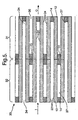
- FIGS 1 and 2 illustrate one embodiment of an exhaust treatment device 10 that generally comprises a plurality of porous filter elements 12.
- Plugs 14 are interposed at and between alternating ends of the filter elements 12 to form inlet channels 16 and outlet channels 18, i.e., a serpentine-like cross sectional structure as shown.
- the filter elements 12 are planar and equally spaced apart from adjacent filter elements.
- the serpentine-like structure as shown is preferred, other wall flow shapes can be employed, e.g., a honeycomb geometry, with the combs being any multi-sided or rounded shape, with substantially square, triangular, pentagonal, hexagonal, heptagonal, or octagonal or similar geometries preferred due to ease of manufacturing and increased surface area.
- the plugs 14 could be disposed in a regular or random pattern throughout the combs. Suitable assembled filter elements and plugs can be commercially obtained from NGK, Japan, Coming Incorporated, USA, and lbiden Company Limited, Japan.
- the exhaust gas enters inlet channels 16 and is forced through pores contained within the filter elements 12, and then exits the exhaust treatment device 10 through outlet channels 18.
- the outermost filter elements may be provided with a mounting flange (not shown) or the like for attachment to an exhaust conduit.
- a catalyst material 22 designed for soot combustion i.e., a soot oxidation catalyst composition
- a catalyst material 24 designed for reducing NOx emissions i.e., a NOx absorber composition
- the NOx absorber composition 24 may also be disposed on the surfaces of the filter elements 12 that form the inlet channel 16 or on a combination of surfaces of the filter elements 12 that form the inlet 16 and outlet channels 18.
- the thickness or loading of the catalyst materials 22, 24 on any surface of the filter elements 12 is preferably at a thickness effective to prevent an excessive pressure drop e.g., a pressure drop less than or equal to 30 kPa.
- the catalyst materials 22 and/or 24 can be applied to a portion of the plug 14 (i.e., plug surfaces that form the inlet channel 16 and/or outlet channel 18) in addition to the; surfaces of the filter elements 12.
- passive regeneration of the filter element can occur via soot combustion by N02, or during the rich excursions aimed at regenerating the NOx adsorber catalyst.
- the exhaust treatment device 10 is preferably disposed in an exhaust conduit in close proximity to the engine to minimize the temperature losses of the exhaust gas to the environment as it flows through exhaust conduit.
- Periodic regeneration at elevated temperatures of the catalyst materials 22 or 24 disposed on the surfaces of the filter elements 12 may be employed to remove soot buildup and/or for adsorption, release, and/or conversion of NOx gases.
- temperature losses inherent to the heat capacity of one catalytic device placed in front of the other is eliminated.
- control of the temperature of exhaust gases is easily regulated.
- an electric heater, light oil bumer, or other heating device may be disposed upstream and in thermal communication with the integral exhaust treatment device 10 to produce the temperatures effective for periodic regeneration and/or for adsorption, release, and/or conversion of NOx gases.
- Figure 3 illustrates one embodiment of the exhaust treatment device 10, wherein the NOx absorber composition 24 designed for reducing NOx emissions is disposed on surfaces of the filter elements 12 and optionally, the surfaces of the plugs 14, adjacent to channels 16 and 18 (soot oxidation catalyst composition 22 is not present).
- the exhaust treatment device 10 can be utilized in exhaust stream applications where high levels of NOx emissions reduction are required, for instance under the United States Tier 2 standards to be phased in beginning in the year 2004.
- both the NOx absorber composition 24 designed for reducing NOx emissions and the soot oxidation catalyst composition 22 designed for soot combustion are disposed as a mixture, on surfaces of the filter elements adjacent to inlet channel 16.
- the surfaces of the filter elements 12 that form inlet channel 16 have a single layer containing a mixture of the different catalyst materials.
- the order and number of layers can vary. However, the number and overall thickness of the layers is chosen in order to avoid excessive pressure drop during operation.
- the filter elements 12 preferably have a size and a geometry chosen to optimize the surface area in a given particulate filter design.
- the filter elements 12 can comprise any material designed for use in a spark ignition or diesel engine environment and preferably has the following characteristics: (1) capable of operating at temperatures up to 1,000 °C or so, depending upon the device's location within the exhaust system; (2) capable of withstanding exposure to hydrocarbons, nitrogen oxides, carbon monoxide, particulate matter (e.g,. soot and the like), carbon dioxide, and/or sulfur; and (3) provides sufficient surface area and structural integrity to support a catalyst, e.g., a washcoat, coating, or the like.
- a catalyst e.g., a washcoat, coating, or the like.
- Some possible suitable materials include cordierite, silicon carbide, mullite, refractory oxides (e.g., alkali zirconium phosphate), metal, metal oxides (e.g., alumina, and the like), glasses, and the like, and mixtures comprising at least one of the foregoing materials.
- These materials can be in the form of foils, porous materials, sponges, and the like, e.g., metallic foils, open pore alumina sponges, and porous ultra-low expansion glasses.
- the NOx adsorber composition 24 preferably comprises a washcoat comprising a porous support, a catalytic metal component, and one or more NOx trapping materials (such as alkali metals, alkaline earth metals, and the like, and combinations comprising at least one of the foregoing) disposed thereon.
- the catalytic metal component and NOx trapping materials can be impregnated, loaded, imbibed, coated, or otherwise disposed on and/or within the porous support.
- the porous support preferably comprises cerium oxide (CeO2), zirconium oxide (ZrO2), lanthanum oxide (La2O3), yttrium oxide (Y2O3), and neodymium oxide (Nd2O3), and the like, as well as combinations comprising at least one of these metal oxides.
- the porous support optionally comprises one or more other support materials suitable for use at the high operation temperatures associated with an internal combustion engine (e.g., up to 1,000 °C).
- Such materials include, but are not limited to, zeolite, alumina, and the like, as well as combinations comprising at least one of the foregoing, with gamma-alumina, theta-alumina, delta-alumina, and combinations comprising at least one of the foregoing materials being preferred.
- the porous support may comprise up to 50 wt% of a cerium-containing mixed oxide, the balance being other support materials; with 3 wt% to 25 wt% cerium-containing mixed oxide, the balance being other support materials being more preferred.
- the washcoat has a catalytic metal component capable of converting NOx to nitrogen disposed on and/or in the porous support.
- the catalytic metal component comprises platinum group metals, such as, platinum (Pt), rhodium (Rh), palladium (Pd), ruthenium (Ru), iridium (ir), and osmium (Os), as well as alloys and combinations comprising at least one of the foregoing.
- the washcoat is loaded with the catalytic metal component in an amount less than or equal to 5 weight percent (wt%) of the washcoat based upon the total weight of the washcoat solids, with an amount of 0.2 wt% to 3 wt% more preferred, and an amount of 0.5 wt% to 2.5 wt% especially preferred.
- wt% weight percent
- the catalytic metal component is a combination of platinum with one or more other metals
- the other metals e.g., palladium, rhodium and the like
- the catalytic metal component can comprise up to 85 wt% platinum and up to 45 wt% palladium (or other metal); with 55 wt% to 80 wt% platinum and 20 wt% to 45 wt% palladium preferred based upon the total weight of the catalyst combination.
- the catalytic metal component can comprise up to 95 wt% platinum and up to 30 wt% rhodium; with 70 wt% to 85 wt% platinum and 2.5 wt% to 20 wt% rhodium preferred; and 70 wt% to 80 wt% platinum and 5 wt% to 10 wt% rhodium especially preferred based upon the total weight of the catalyst combination.
- the porous support may be further loaded with one or more NOx trapping materials, such as alkali metals, alkaline earth metal, and mixtures comprising at least one of the foregoing.
- Suitable trapping materials include barium (Ba), lithium (Li), potassium (K), magnesium (Mg), sodium (Na), cesium (Cs), strontium (Sr), and combinations comprising at least one of the foregoing, with a mixture of Ba and K being preferred.
- the washcoat comprises less than or equal to 50 wt% trapping material, with an amount of 1wt% to 40 wt% preferred, and an amount of 5 wt% to 20 wt% being especially preferred, based upon the total weight of the washcoat.
- the Ba is present in an amount up to 30 wt% of the washcoat, and K is present in an amount up to 10 wt%. More preferably, the trapping material comprises Ba in an amount of 7 wt% to 20 wt% of the washcoat, and K in the amount of 2 wt% to 5 wt% of the washcoat.
- the washcoat is supported on the filter elements 12, which are suitably stable in the high temperature exhaust gas environment (e.g., up to 1,000 °C).
- Formation of the NOx adsorber composition onto the filter element 12 comprises application of the washcoat as a mixture.
- the porous support, catalytic metal component, and/or trapping materials can be combined to form a slurry.
- the slurry can then be applied to the filter elements 12.
- the washcoat is first applied to the filter elements 12 followed by drying and calcination.
- the catalytic metal component and trapping materials can then be deposited on or within the washcoat by any suitable manner, such as by impregnation techniques.
- the catalytic metal component and trapping materials individually or together, can be dissolved as soluble precursors (e.g., as a salt like potassium nitrate) in an aqueous or organic solvent, which is then impregnated into the porous support.
- soluble precursors e.g., as a salt like potassium nitrate
- the catalytic metal components are impregnated prior to the trapping materials.
- the trapping material and catalytic metal component precursors can also be dissolved together in a common solution and impregnated into the washcoat in a single step.
- loading of the catalytic metal component onto the washcoat may be accomplished with a catalytic metal precursor solution.
- Suitable precursor solutions are aqueous solutions, which facilitate efficient chemisorption of the catalytic metal onto the washcoat.
- Suitable precursor solutions include platinum nitrate solution, platinum chloride solution, and similar materials and combinations thereof, with platinum nitrate solution being preferred.
- the catalytic metal precursor solution can be applied to the cerium-containing mixed oxide prior to mixing with other washcoat components.
- the washcoat comprises alumina and a cerium-containing mixed oxide
- alumina is added after the precursor solution is applied to the mixed oxide.
- This preparation method facilitates the selective deposition of catalytic metal onto the cerium-containing mixed oxide surface, rather than onto other components of the porous support (e.g., the other support materials, such as BaCO3 and Al2O3). Selective deposition of platinum can enhance the NOx adsorber catalyst resistance to sulfur poisoning.
- the soot oxidation catalyst composition 22 preferably comprises a catalyst composition formed from an inorganic precursor and a catalytic metal.
- the catalyst is a,catalytically active metal that reacts with and converts pollutants (e.g., HC, CO and/or NOx and the like) to water, CO2, N2 and the like.
- pollutants e.g., HC, CO and/or NOx and the like
- the catalyst materials 22 reduce the concentration of at least one component of the exhaust gas.
- a preferred soot oxidation catalyst composition is one that can be disposed on the surfaces of the filter elements 12 such that a minimal pressure drop increase is observed as exhaust passes through the filter element 12.
- the pressure drop when the exhaust passes through the filter element 12 increases with the amount of particulates collected in the trap. If the pressure drop is too high, the engine performance may be hampered due to increased backpressure. Thus, the filter element 12 should keep the pressure drop at a minimal level at the beginning of use as well as after a large amount of particulates have been collected in the trap.
- a preferred pressure drop is equal to or below 30 kPa (kilopascals).
- the inorganic precursor can comprise an alkali metal aluminate precursor.
- the alkali metal aluminate precursor is preferably formed by the protocol of, for example, U.S. Patent No. 5,614,596.
- An alkali metal aluminate precursor can be formed by the reaction of an alkali hydroxide, aluminum hydroxide and a complexing agent.
- Preferred complexing agents are triethanolamine (TEA) and trisopropanolamine (TIPA).
- TIPA triethanolamine
- a preferred alkali metal aluminate precursor is formed by reacting (e.g. distilling) lithium hydroxide, aluminum hydroxide, and TEA.
- alkali metal aluminate precursor is formed by reacting (e.g., distilling) potassium hydroxide, aluminum hydroxide, and TEA.
- Yet another preferred alkali metal aluminate precursor is formed by reacting (e.g., distilling) cesium hydroxide, aluminum hydroxide, and TEA.
- the alkali metal aluminate precursor is preferably a polymer containing metal-triethanolamine complexes.
- the resulting solution is referred to as an alkali metal aluminate precursor because calcination of this solution (e.g., at temperatures of 500 to 800 °C), will result in the production of the corresponding alkali metal aluminate.
- Some possible alkali metal aluminates include lithium aluminate, potassium aluminate and cesium aluminate. Formation of an alkali metal aluminate can be confirmed by X-ray diffraction.
- the catalyst is a catalytically active metal that reacts with and converts pollutants (e.g., HC, CO and/or NOx and the like) to water, CO2, N2 and the like.
- pollutants e.g., HC, CO and/or NOx and the like
- Typical catalytically active metals include platinum (Pt), palladium, rhodium, iridium, osmium, ruthenium, tantalum, zirconium, yttrium, cerium, nickel, copper, and the like, as well as combinations comprising at least one of the foregoing metals, and other catalysts, with platinum preferred.
- the catalytic metal is preferably incorporated into the inorganic precursor to provide an atomically isolated, and substantially uniformly dispersed catalyst.
- a preferred method of dispersing the catalytic metal in the inorganic precursor is to calcine an alkali metal aluminate precursor and a catalytic metal salt to produce a mixture of alkali metal aluminate and alkali metal catalytic metal oxide.
- Preferred catalytic metal salts are platinum nitrate, platinum sulfite, and platinum hydroxides such as Pt(OH)6 (ethanolamine)2 (platinum ethanolamine hydroxide) and Pt(NH3)4(OH)2 (platinum amino hydroxide). Platinum nitrate and platinum hydroxides are particularly preferred.
- a preferred method to form the mixture of alkali metal aluminate and alkali metal catalytic metal oxide is to calcine an alkali metal aluminate precursor in the presence of a catalytic metal salt.
- a preferred method is to heat the mixture to a temperature sufficient to remove non-reacted triethanolamine (TEA). Once the TEA is removed, the temperature is increased to a sufficient temperature to decompose metal triethanolamine complexes. Finally the temperature is increased to a third temperature sufficient to form the mixture of alkali metal aluminate and alkali metal catalytic metal oxide.
- TEA non-reacted triethanolamine
- a mixture of lithium aluminate precursor and platinum nitrate can be heated up to 150 °C to remove any non-reacted TEA, then heated up to 400 °C to decompose metal triethanolamine complexes, and then heated up to 450 to 650 °C to form the mixture of alkali metal aluminate and alkali metal catalytic metal oxide. Heating to 450 to 650 °C is sufficient to form a mixture of alkali metal aluminate and alkali metal catalytic metal oxide as well as some unreacted catalytic metal.
- the mixture of alkali metal aluminate, alkali metal catalytic metal oxide and catalytic metal can be calcined again for a sufficient time and at a sufficient temperature to convert any remaining catalytic metal to the alkali metal catalytic metal oxide, (e.g., at up to 750 to 900 °C for up to 16 hours).
- the mixture of alkali metal aluminate and alkali metal catalytic metal oxide, which is now substantially free of unreacted catalytic metal can also be used for catalytic diesel particulate filter applications.
- a mixture of alkali metal aluminate and alkali metal catalytic metal oxide, which is substantially free of unreacted catalytic metal, preferably comprises less than or equal to 5% unreacted catalytic metal, more preferably less than or equal to 2% unreacted catalytic metal.
- the method described in this disclosure provides a substantially uniform dispersion of the alkali metal catalytic metal oxide in the alkali metal aluminate.
- a substantially uniform dispersion of catalytic metal oxide exhibits a crystalline domain size calculated using Scherer Equation from full-width-at-maximum-intensity of the (003) X-ray diffraction peak of less than 500 ANGSTROM (Angstroms).
- the mixture of alkali metal aluminate and alkali metal catalytic metal oxide can also be formed by, for example, reacting an alkali metal carbonate and a metallic platinum compound (JCPDS card No. 29-0820).
- Forming the inorganic precursor and the catalyst in the same reaction as described in the present disclosure has the advantage of producing a substantially uniform dispersion of the catalyst.
- Substantially uniform dispersion of the catalytic metal can provide a more effective catalyst.
- An additional feature of the catalyst disclosed herein is that the catalytic metal in the alkali metal catalytic metal oxide maintains its catalytic activity in the complex.
- the alkali metal catalytic metal oxide can also be made by impregnation of a catalytic metal salt such at Pt nitrate onto an alkali metal aluminate powder.
- the resulting powder can be calcined for a sufficient time and at a sufficient temperature to produce the alkali metal catalytic metal oxide, for example, calcining at 500 to 800 °C for 16 hours in air.
- the soot oxidation catalyst material 22 e.g., the alkali metal aluminate and the alkali metal catalytic metal oxide.
- the catalyst material 22 can be coated, imbibed, impregnated, physisorbed, chemisorbed, precipitated, or otherwise applied to the filter elements 12.
- Application of the catalyst material 22 to the filter element 12 can be accomplished by such techniques as spraying, dipping, or painting, for example.
- a preferred quantity of the alkali metal aluminate/alkali metal catalytic metal oxide composition is that sufficient to catalyze a reduction in concentration of at least one exhaust gas component.
- a preferred catalyst composition loading density is 0.01 to 0.5 g/in 3 (grams/cubic inch) (0.00061 to 0.031 g/cm 3 (grams per cubic centimeter)), with 0.1 to 0.2 g/in 3 (0.0061 to 0.12 g/cm 3 ) more preferred.
- a preferred catalytic metal loading is 0.0011 to 0.058 g/in 3 (0.000067 to 0.0035 g/cm 3 ) with 0.0058 to 0.041 g/in 3 (0.00035 to 0.0025 g/cm 3 ) more preferred.
- the alkali metal aluminate/alkali metal catalytic metal oxide composition be deposited onto the filter elements 12 in an amount that gives a back-pressure-drop increase of less than or equal to 30 kPa.
- a method of using the exhaust treatment device 10, 30 or 50 comprises mounting the exhaust treatment device 10, 30 or 50 in an exhaust conduit, such that an exhaust gas discharged from an engine flows through the exhaust treatment device 10, 30, or 50 prior to being discharged to the external environment.
- the exhaust treatment device removes soot, particulate matter, and removes NOx from an exhaust gas stream. Under lean operating conditions, NOx is adsorbed by the NOx adsorber catalyst composition whereas under rich operating conditions NOx is released and converted to nitrogen.
- the exhaust treatment devices in accordance with the present disclosure provide simultaneous reduction of particulate matter and undesirable gases from an exhaust gas flowing through the exhaust treatment device. Moreover, regeneration (soot oxidation,catalyst composition 22) and desulfurization (NOx adsorber composition 24) of the exhaust treatment devices 10, 30, 50 can occur since temperature losses inherent to the heat capacity of one catalytic device placed in front of the other are eliminated.
Landscapes
- Engineering & Computer Science (AREA)
- Chemical & Material Sciences (AREA)
- Combustion & Propulsion (AREA)
- Mechanical Engineering (AREA)
- General Engineering & Computer Science (AREA)
- Chemical Kinetics & Catalysis (AREA)
- Health & Medical Sciences (AREA)
- Biomedical Technology (AREA)
- Environmental & Geological Engineering (AREA)
- Analytical Chemistry (AREA)
- General Chemical & Material Sciences (AREA)
- Oil, Petroleum & Natural Gas (AREA)
- Exhaust Gas After Treatment (AREA)
Description
- The present disclosure relates to NOx and particle abatement, particularly with NOx and particle abatement in exhaust gas streams discharged from automotive engines.
- In order to meet government mandated exhaust gas emission standards, the exhaust gases of an automotive internal combustion engine must be treated before emission into the atmosphere. Exhaust gas streams are typically passed through a device containing a catalytic element to remove undesirable gaseous emission components such as unburned hydrocarbons, carbon monoxide and nitrogen oxides. The removal of NOx components is of particular concern, and can be accomplished using a device employing elements containing a NOx adsorber catalyst. However, NOx adsorber catalysts are sensitive to sulfur poisoning and must be periodically desulfurized, otherwise their performance gradually decreases.
- In addition to the gaseous components, exhaust gas streams also contain particulate matter such as carbon-containing particles or soot. A particulate filter, also commonly used with compression ignition engines, is used to prevent the carbon particles or soot from exiting the tailpipe. The particulate filter is typically a stand-alone device separate and distinct from devices employing catalytic elements for removing undesirable NOx gaseous components. Carbon particles are trapped in the particulate filter and continuously and/or periodically burned so that the filter is regenerated and able to again trap the carbon particles.
- A catalytic particulate filter comprises a substrate and a catalyst composition typically formed from an inorganic precursor and a catalytic metal. The catalytic particulate filter catalyzes the removal of pollutants from exhaust gases as well as removes particulate from the exhaust gas stream. The catalyst composition is optimized for periodically regenerating the filter.
- If the catalytic element and particulate filter (or catalytic particulate filter) are separate elements, they require a large installation space in the exhaust line, which is usually not available, as well as a high installation cost. Moreover, since the devices are serially mounted in the : exhaust line, temperature losses inherent to heat capacity would affect the regeneration or desulfurization capabilities of the subsequent device since the regeneration or desulfurization of the respective device is thermally controlled.
WO-A-01.012320, EP-A-1.101.908, WO-A-00.32911 and EP-A-0.984.142 all refer to an exhaust gas filter with plural parallel channels plugged off altematingly with the inlet side coated with a soot oxidation catalyst and the outlet side coated with a NOx adsorber. - The present invention in its various aspects is as set out in the accompanying claims.
- Referring now to the figures wherein the like elements are numbered alike:
- Figure 1 shows a cross sectional view of an exhaust treatment device;
- Figure 2 shows a side view of the exhaust treatment device taken along the lines A-A of Figure 1;
- Figure 3 shows a cross sectional view of an exhaust treatment device in accordance with another embodiment;
- Figure 4 shows a cross sectional view of an exhaust treatment device in accordance with a third embodiment;
- Figure 5 shows a cross sectional view of an exhaust treatment device in accordance with a fourth embodiment; and
- Figure 6 shows a cross sectional view of an exhaust treatment device in accordance with a fifth embodiment.
- Disclosed herein is an exhaust treatment device comprising a plurality of filter elements and plugs alternately arranged in a serpentine-like structure to form a plurality of inlet channels and outlet channels, wherein the plugs are disposed at alternating ends of the filter elements, and wherein fluid communication from the inlet channels to the outlet channels is through the filter elements; a NOx adsorber composition disposed on and/or impregnated in surfaces of the filter elements or filter elements and plugs that form the inlet channels or outlet channels or a combination of the inlet and outlet channels; and a soot oxidation catalyst composition formed from an inorganic precursor and a catalytic metal disposed on or impregnated in surfaces of the filter elements or filter elements and plugs that form the inlet channels.
- In another embodiment, the exhaust treatment device comprises a first block in fluid communication with a second block, the first block comprising a plurality of filter elements and plugs alternately arranged in a serpentine-like structure to form a plurality of inlet channels and outlet channels, wherein the plugs are disposed at alternating ends of the filter elements, and wherein fluid communication from the inlet channels to the outlet channels is through the filter elements, a soot oxidation catalyst composition formed from an inorganic precursor and a catalytic metal disposed on or impregnated in surfaces that form the inlet channels, and a NOx adsorber composition disposed on or impregnated in surfaces of the filter elements or the surfaces of the filter elements and plugs that form the inlet or outlet channels or combination thereof; and the second block comprising a plurality of filter elements and plugs arranged to form a plurality of open-ended passageways, wherein the filter elements of the second block comprise a thickness less than a thickness of the filter elements in the first block, and wherein the NOx adsorber composition is disposed on or impregnated in surfaces of the filter elements or the surfaces of the filter elements and plugs that form the open-ended passageways.
- A method of treating an exhaust gas stream comprises mounting an exhaust treatment device in an exhaust conduit, wherein the exhaust treatment device comprising a plurality of filter elements and plugs alternately arranged in a serpentine-like structure to form a plurality of inlet channels and outlet channels, wherein the plugs are disposed at alternating ends of the filter elements, and wherein fluid communication from the inlet channels to the outlet channels is through the filter elements, a NOx adsorber composition disposed on and/or impregnated in surfaces of the filter elements, or filter elements and plugs, that form the inlet channels or outlet channels or combination thereof, and a soot oxidation catalyst composition formed from an inorganic precursor and a catalytic metal disposed on or impregnated in surfaces of the filter elements or filter elements and plugs that form the inlet channels; flowing the exhaust gas stream into the inlet channels of the exhaust treatment device and contacting the soot oxidation catalyst composition, the NOx adsorber composition, or the combination thereof; filtering the exhaust gas stream by flowing through the filter element; and discharging the exhaust gas stream from the exhaust treatment device, wherein the exhaust gas stream further contacts the NOx adsorber composition.
- Further advantages will be understood by those skilled in the art in light of the detailed description and figures.
- Disclosed herein is an exhaust treatment device that combines the functionalities of a catalytic particulate filter and a NOx absorber catalyst into a single integral device for use downstream from an engine, e.g., preferably manifold mounted or close coupled. As will be described in further detail, the exhaust treatment device effectively removes particulate soot and reduces concentration of NOx as well as optionally reducing the concentration of unburned hydrocarbons, carbon monoxide, and other undesirable exhaust gas components, from exhaust gases flowing through the exhaust conduit.
- Figures 1 and 2 illustrate one embodiment of an
exhaust treatment device 10 that generally comprises a plurality ofporous filter elements 12.Plugs 14 are interposed at and between alternating ends of thefilter elements 12 to forminlet channels 16 andoutlet channels 18, i.e., a serpentine-like cross sectional structure as shown. Preferably, thefilter elements 12 are planar and equally spaced apart from adjacent filter elements. Although the serpentine-like structure as shown is preferred, other wall flow shapes can be employed, e.g., a honeycomb geometry, with the combs being any multi-sided or rounded shape, with substantially square, triangular, pentagonal, hexagonal, heptagonal, or octagonal or similar geometries preferred due to ease of manufacturing and increased surface area. In this embodiment, theplugs 14 could be disposed in a regular or random pattern throughout the combs. Suitable assembled filter elements and plugs can be commercially obtained from NGK, Japan, Coming Incorporated, USA, and lbiden Company Limited, Japan. - In operation, the exhaust gas enters
inlet channels 16 and is forced through pores contained within thefilter elements 12, and then exits theexhaust treatment device 10 throughoutlet channels 18. The outermost filter elements may be provided with a mounting flange (not shown) or the like for attachment to an exhaust conduit. - A
catalyst material 22 designed for soot combustion, i.e., a soot oxidation catalyst composition, is preferably disposed on surfaces of thefilter elements 12 that form theinlet channel 16. Similarly, acatalyst material 24 designed for reducing NOx emissions, i.e., a NOx absorber composition, is preferably disposed on surfaces of the filter elements that form theoutlet channel 18. Optionally, theNOx absorber composition 24 may also be disposed on the surfaces of thefilter elements 12 that form theinlet channel 16 or on a combination of surfaces of thefilter elements 12 that form theinlet 16 andoutlet channels 18. The thickness or loading of thecatalyst materials filter elements 12 is preferably at a thickness effective to prevent an excessive pressure drop e.g., a pressure drop less than or equal to 30 kPa. - Optionally, the
catalyst materials 22 and/or 24 can be applied to a portion of the plug 14 (i.e., plug surfaces that form theinlet channel 16 and/or outlet channel 18) in addition to the; surfaces of thefilter elements 12. In this manner, passive regeneration of the filter element can occur via soot combustion by N02, or during the rich excursions aimed at regenerating the NOx adsorber catalyst. - The
exhaust treatment device 10 is preferably disposed in an exhaust conduit in close proximity to the engine to minimize the temperature losses of the exhaust gas to the environment as it flows through exhaust conduit. Periodic regeneration at elevated temperatures of thecatalyst materials filter elements 12 may be employed to remove soot buildup and/or for adsorption, release, and/or conversion of NOx gases. With the above-described integralexhaust treatment device 10, temperature losses inherent to the heat capacity of one catalytic device placed in front of the other is eliminated. As a result, control of the temperature of exhaust gases is easily regulated. For example, an electric heater, light oil bumer, or other heating device may be disposed upstream and in thermal communication with the integralexhaust treatment device 10 to produce the temperatures effective for periodic regeneration and/or for adsorption, release, and/or conversion of NOx gases. - Figure 3 illustrates one embodiment of the
exhaust treatment device 10, wherein theNOx absorber composition 24 designed for reducing NOx emissions is disposed on surfaces of thefilter elements 12 and optionally, the surfaces of theplugs 14, adjacent tochannels 16 and 18 (sootoxidation catalyst composition 22 is not present). Theexhaust treatment device 10 can be utilized in exhaust stream applications where high levels of NOx emissions reduction are required, for instance under the United States Tier 2 standards to be phased in beginning in the year 2004. In an alternative embodiment, both theNOx absorber composition 24 designed for reducing NOx emissions and the sootoxidation catalyst composition 22 designed for soot combustion are disposed as a mixture, on surfaces of the filter elements adjacent toinlet channel 16. Thus, the surfaces of thefilter elements 12 that forminlet channel 16 have a single layer containing a mixture of the different catalyst materials. In the case of individual layers, the order and number of layers can vary. However, the number and overall thickness of the layers is chosen in order to avoid excessive pressure drop during operation. - The
filter elements 12 preferably have a size and a geometry chosen to optimize the surface area in a given particulate filter design. Thefilter elements 12 can comprise any material designed for use in a spark ignition or diesel engine environment and preferably has the following characteristics: (1) capable of operating at temperatures up to 1,000 °C or so, depending upon the device's location within the exhaust system; (2) capable of withstanding exposure to hydrocarbons, nitrogen oxides, carbon monoxide, particulate matter (e.g,. soot and the like), carbon dioxide, and/or sulfur; and (3) provides sufficient surface area and structural integrity to support a catalyst, e.g., a washcoat, coating, or the like. Some possible suitable materials include cordierite, silicon carbide, mullite, refractory oxides (e.g., alkali zirconium phosphate), metal, metal oxides (e.g., alumina, and the like), glasses, and the like, and mixtures comprising at least one of the foregoing materials. These materials can be in the form of foils, porous materials, sponges, and the like, e.g., metallic foils, open pore alumina sponges, and porous ultra-low expansion glasses. - The
NOx adsorber composition 24 preferably comprises a washcoat comprising a porous support, a catalytic metal component, and one or more NOx trapping materials (such as alkali metals, alkaline earth metals, and the like, and combinations comprising at least one of the foregoing) disposed thereon. The catalytic metal component and NOx trapping materials can be impregnated, loaded, imbibed, coated, or otherwise disposed on and/or within the porous support. - The porous support preferably comprises cerium oxide (CeO2), zirconium oxide (ZrO2), lanthanum oxide (La2O3), yttrium oxide (Y2O3), and neodymium oxide (Nd2O3), and the like, as well as combinations comprising at least one of these metal oxides.
- The porous support optionally comprises one or more other support materials suitable for use at the high operation temperatures associated with an internal combustion engine (e.g., up to 1,000 °C). Such materials include, but are not limited to, zeolite, alumina, and the like, as well as combinations comprising at least one of the foregoing, with gamma-alumina, theta-alumina, delta-alumina, and combinations comprising at least one of the foregoing materials being preferred. The porous support may comprise up to 50 wt% of a cerium-containing mixed oxide, the balance being other support materials; with 3 wt% to 25 wt% cerium-containing mixed oxide, the balance being other support materials being more preferred.
- The washcoat has a catalytic metal component capable of converting NOx to nitrogen disposed on and/or in the porous support. The catalytic metal component comprises platinum group metals, such as, platinum (Pt), rhodium (Rh), palladium (Pd), ruthenium (Ru), iridium (ir), and osmium (Os), as well as alloys and combinations comprising at least one of the foregoing. Preferably, the washcoat is loaded with the catalytic metal component in an amount less than or equal to 5 weight percent (wt%) of the washcoat based upon the total weight of the washcoat solids, with an amount of 0.2 wt% to 3 wt% more preferred, and an amount of 0.5 wt% to 2.5 wt% especially preferred.
- Where the catalytic metal component is a combination of platinum with one or more other metals, the other metals, e.g., palladium, rhodium and the like, are typically present in an amount less than the platinum. More particularly, with a platinum/palladium combination, the catalytic metal component can comprise up to 85 wt% platinum and up to 45 wt% palladium (or other metal); with 55 wt% to 80 wt% platinum and 20 wt% to 45 wt% palladium preferred based upon the total weight of the catalyst combination. With a platinum/rhodium combination, for example, the catalytic metal component can comprise up to 95 wt% platinum and up to 30 wt% rhodium; with 70 wt% to 85 wt% platinum and 2.5 wt% to 20 wt% rhodium preferred; and 70 wt% to 80 wt% platinum and 5 wt% to 10 wt% rhodium especially preferred based upon the total weight of the catalyst combination.
- In addition to the catalytic metal component, the porous support may be further loaded with one or more NOx trapping materials, such as alkali metals, alkaline earth metal, and mixtures comprising at least one of the foregoing. Suitable trapping materials include barium (Ba), lithium (Li), potassium (K), magnesium (Mg), sodium (Na), cesium (Cs), strontium (Sr), and combinations comprising at least one of the foregoing, with a mixture of Ba and K being preferred. Generally, the washcoat comprises less than or equal to 50 wt% trapping material, with an amount of 1wt% to 40 wt% preferred, and an amount of 5 wt% to 20 wt% being especially preferred, based upon the total weight of the washcoat. For example, in the case of a trapping material comprising a Ba and K mixture, the Ba is present in an amount up to 30 wt% of the washcoat, and K is present in an amount up to 10 wt%. More preferably, the trapping material comprises Ba in an amount of 7 wt% to 20 wt% of the washcoat, and K in the amount of 2 wt% to 5 wt% of the washcoat.
- The washcoat is supported on the
filter elements 12, which are suitably stable in the high temperature exhaust gas environment (e.g., up to 1,000 °C). - Formation of the NOx adsorber composition onto the
filter element 12 comprises application of the washcoat as a mixture. For example, the porous support, catalytic metal component, and/or trapping materials can be combined to form a slurry. The slurry can then be applied to thefilter elements 12. Preferably, however, the washcoat is first applied to thefilter elements 12 followed by drying and calcination. The catalytic metal component and trapping materials can then be deposited on or within the washcoat by any suitable manner, such as by impregnation techniques. For example, the catalytic metal component and trapping materials, individually or together, can be dissolved as soluble precursors (e.g., as a salt like potassium nitrate) in an aqueous or organic solvent, which is then impregnated into the porous support. Preferably, the catalytic metal components are impregnated prior to the trapping materials. - Alternatively, the trapping material and catalytic metal component precursors can also be dissolved together in a common solution and impregnated into the washcoat in a single step. For example, loading of the catalytic metal component onto the washcoat may be accomplished with a catalytic metal precursor solution. Suitable precursor solutions are aqueous solutions, which facilitate efficient chemisorption of the catalytic metal onto the washcoat. Suitable precursor solutions include platinum nitrate solution, platinum chloride solution, and similar materials and combinations thereof, with platinum nitrate solution being preferred.
- The catalytic metal precursor solution can be applied to the cerium-containing mixed oxide prior to mixing with other washcoat components. For example, in an embodiment wherein the washcoat comprises alumina and a cerium-containing mixed oxide, alumina is added after the precursor solution is applied to the mixed oxide. This preparation method facilitates the selective deposition of catalytic metal onto the cerium-containing mixed oxide surface, rather than onto other components of the porous support (e.g., the other support materials, such as BaCO3 and Al2O3). Selective deposition of platinum can enhance the NOx adsorber catalyst resistance to sulfur poisoning.
- The soot
oxidation catalyst composition 22 preferably comprises a catalyst composition formed from an inorganic precursor and a catalytic metal. The catalyst is a,catalytically active metal that reacts with and converts pollutants (e.g., HC, CO and/or NOx and the like) to water, CO2, N2 and the like. Thecatalyst materials 22 reduce the concentration of at least one component of the exhaust gas. - A preferred soot oxidation catalyst composition is one that can be disposed on the surfaces of the
filter elements 12 such that a minimal pressure drop increase is observed as exhaust passes through thefilter element 12. The pressure drop when the exhaust passes through thefilter element 12 increases with the amount of particulates collected in the trap. If the pressure drop is too high, the engine performance may be hampered due to increased backpressure. Thus, thefilter element 12 should keep the pressure drop at a minimal level at the beginning of use as well as after a large amount of particulates have been collected in the trap. A preferred pressure drop is equal to or below 30 kPa (kilopascals). - The inorganic precursor can comprise an alkali metal aluminate precursor. The alkali metal aluminate precursor is preferably formed by the protocol of, for example, U.S. Patent No. 5,614,596. An alkali metal aluminate precursor can be formed by the reaction of an alkali hydroxide, aluminum hydroxide and a complexing agent. Preferred complexing agents are triethanolamine (TEA) and trisopropanolamine (TIPA). A preferred alkali metal aluminate precursor is formed by reacting (e.g. distilling) lithium hydroxide, aluminum hydroxide, and TEA. Another preferred alkali metal aluminate precursor is formed by reacting (e.g., distilling) potassium hydroxide, aluminum hydroxide, and TEA. Yet another preferred alkali metal aluminate precursor is formed by reacting (e.g., distilling) cesium hydroxide, aluminum hydroxide, and TEA. The alkali metal aluminate precursor is preferably a polymer containing metal-triethanolamine complexes. The resulting solution is referred to as an alkali metal aluminate precursor because calcination of this solution (e.g., at temperatures of 500 to 800 °C), will result in the production of the corresponding alkali metal aluminate. Some possible alkali metal aluminates include lithium aluminate, potassium aluminate and cesium aluminate. Formation of an alkali metal aluminate can be confirmed by X-ray diffraction.
- The catalyst is a catalytically active metal that reacts with and converts pollutants (e.g., HC, CO and/or NOx and the like) to water, CO2, N2 and the like. Typical catalytically active metals include platinum (Pt), palladium, rhodium, iridium, osmium, ruthenium, tantalum, zirconium, yttrium, cerium, nickel, copper, and the like, as well as combinations comprising at least one of the foregoing metals, and other catalysts, with platinum preferred.
- The catalytic metal is preferably incorporated into the inorganic precursor to provide an atomically isolated, and substantially uniformly dispersed catalyst. A preferred method of dispersing the catalytic metal in the inorganic precursor is to calcine an alkali metal aluminate precursor and a catalytic metal salt to produce a mixture of alkali metal aluminate and alkali metal catalytic metal oxide. Preferred catalytic metal salts are platinum nitrate, platinum sulfite, and platinum hydroxides such as Pt(OH)6 (ethanolamine)2 (platinum ethanolamine hydroxide) and Pt(NH3)4(OH)2 (platinum amino hydroxide). Platinum nitrate and platinum hydroxides are particularly preferred.
- A preferred method to form the mixture of alkali metal aluminate and alkali metal catalytic metal oxide is to calcine an alkali metal aluminate precursor in the presence of a catalytic metal salt. A preferred method is to heat the mixture to a temperature sufficient to remove non-reacted triethanolamine (TEA). Once the TEA is removed, the temperature is increased to a sufficient temperature to decompose metal triethanolamine complexes. Finally the temperature is increased to a third temperature sufficient to form the mixture of alkali metal aluminate and alkali metal catalytic metal oxide. For example, a mixture of lithium aluminate precursor and platinum nitrate can be heated up to 150 °C to remove any non-reacted TEA, then heated up to 400 °C to decompose metal triethanolamine complexes, and then heated up to 450 to 650 °C to form the mixture of alkali metal aluminate and alkali metal catalytic metal oxide. Heating to 450 to 650 °C is sufficient to form a mixture of alkali metal aluminate and alkali metal catalytic metal oxide as well as some unreacted catalytic metal.
- Optionally, the mixture of alkali metal aluminate, alkali metal catalytic metal oxide and catalytic metal can be calcined again for a sufficient time and at a sufficient temperature to convert any remaining catalytic metal to the alkali metal catalytic metal oxide, (e.g., at up to 750 to 900 °C for up to 16 hours). The mixture of alkali metal aluminate and alkali metal catalytic metal oxide, which is now substantially free of unreacted catalytic metal, can also be used for catalytic diesel particulate filter applications. A mixture of alkali metal aluminate and alkali metal catalytic metal oxide, which is substantially free of unreacted catalytic metal, preferably comprises less than or equal to 5% unreacted catalytic metal, more preferably less than or equal to 2% unreacted catalytic metal.
- The method described in this disclosure provides a substantially uniform dispersion of the alkali metal catalytic metal oxide in the alkali metal aluminate. A substantially uniform dispersion of catalytic metal oxide exhibits a crystalline domain size calculated using Scherer Equation from full-width-at-maximum-intensity of the (003) X-ray diffraction peak of less than 500 ANGSTROM (Angstroms). The mixture of alkali metal aluminate and alkali metal catalytic metal oxide can also be formed by, for example, reacting an alkali metal carbonate and a metallic platinum compound (JCPDS card No. 29-0820). Forming the inorganic precursor and the catalyst in the same reaction as described in the present disclosure, however, has the advantage of producing a substantially uniform dispersion of the catalyst. Substantially uniform dispersion of the catalytic metal can provide a more effective catalyst. An additional feature of the catalyst disclosed herein is that the catalytic metal in the alkali metal catalytic metal oxide maintains its catalytic activity in the complex.
- In addition to the above-described methods, the alkali metal catalytic metal oxide can also be made by impregnation of a catalytic metal salt such at Pt nitrate onto an alkali metal aluminate powder. The resulting powder can be calcined for a sufficient time and at a sufficient temperature to produce the alkali metal catalytic metal oxide, for example, calcining at 500 to 800 °C for 16 hours in air.
- Disposed on and/or throughout the
filter elements 12 is the soot oxidation catalyst material 22 (e.g., the alkali metal aluminate and the alkali metal catalytic metal oxide). Thecatalyst material 22 can be coated, imbibed, impregnated, physisorbed, chemisorbed, precipitated, or otherwise applied to thefilter elements 12. Application of thecatalyst material 22 to thefilter element 12 can be accomplished by such techniques as spraying, dipping, or painting, for example. A preferred quantity of the alkali metal aluminate/alkali metal catalytic metal oxide composition is that sufficient to catalyze a reduction in concentration of at least one exhaust gas component. A preferred catalyst composition loading density is 0.01 to 0.5 g/in3 (grams/cubic inch) (0.00061 to 0.031 g/cm3 (grams per cubic centimeter)), with 0.1 to 0.2 g/in3 (0.0061 to 0.12 g/cm3) more preferred. A preferred catalytic metal loading is 0.0011 to 0.058 g/in3 (0.000067 to 0.0035 g/cm3) with 0.0058 to 0.041 g/in3 (0.00035 to 0.0025 g/cm3) more preferred. In addition, it is preferred that the alkali metal aluminate/alkali metal catalytic metal oxide composition be deposited onto thefilter elements 12 in an amount that gives a back-pressure-drop increase of less than or equal to 30 kPa. - A method of using the
exhaust treatment device exhaust treatment device exhaust treatment device - Advantageously, the exhaust treatment devices in accordance with the present disclosure provide simultaneous reduction of particulate matter and undesirable gases from an exhaust gas flowing through the exhaust treatment device. Moreover, regeneration (soot oxidation,catalyst composition 22) and desulfurization (NOx adsorber composition 24) of the
exhaust treatment devices
Claims (21)
- An exhaust treatment device comprising:a plurality of filter elements (12) and plugs (14) alternately arranged in a serpentine-like structure to form a plurality of inlet channels (16) and outlet channels (18), wherein the plugs (14) are disposed at alternating ends of the filter elements (12), and wherein fluid communication from the inlet channels (16) to the outlet channels (18) is through the filter elements (12);a NOx adsorber composition disposed on and/or impregnated in surfaces of the filter elements (12) or filter elements (12) and plugs (14) that form the inlet channels (16) or outlet channels (18) or a combination of the inlet and outlet channels (16, 18); anda soot oxidation catalyst composition formed from an inorganic precursor and a catalytic metal disposed on or impregnated in surfaces of the filter elements (12) or filter elements (12) and plugs (14) that form the inlet channels (16) and, wherein the NOx adsorber composition and the soot oxidation catalyst composition form a mixture and are disposed on or impregnated in surfaces of the filter elements (12) or the surfaces of the filter elements (12) and plugs (14) that form the outlet channels (18) and/or inlet channels (16).
- The exhaust treatment device (10) according to Claim 1, wherein the NOx adsorber composition and the soot oxidation catalytic composition comprise a thickness effective to minimize a pressure drop across the filter elements (12) to less than or equal to 30kPA.
- The exhaust treatment device (10) according to Claim 1, wherein the NOx adsorber composition comprises a washcoat, the washcoat comprising a support material, a cerium-containing mixed oxide, a catalytic metal component, and a trapping material.
- The exhaust treatment device (10) according to Claim 3, wherein the cerium-containing mixed oxide further comprises an oxide selected from the group consisting of zirconium oxide, lanthanum oxide, yttrium oxide, neodymium oxide, and combinations comprising at least one of the foregoing oxides.
- The exhaust treatment device (10) according to Claim 3, wherein the catalytic metal component is selected from the group consisting of platinum, palladium, rhodium, ruthenium, iridium, osmium, and alloys and mixtures comprising at least one of the foregoing.
- The exhaust treatment device (10) according to Claim 3, wherein the catalytic metal component is present in an amount of up to 5 wt%, based upon the total weight of the washcoat.
- The exhaust treatment device (10) according to Claim 3, wherein the catalytic metal component is present in an amount of 0.2 wt% to 3 wt%, based upon the total weight of the washcoat.
- The exhaust treatment device (10) according to Claim 3, wherein the trapping material is selected from the group consisting of alkali metals, alkaline earth metals, and mixtures comprising at least one of the foregoing.
- The exhaust treatment device (10) according to Claim 3, wherein the trapping material is selected from the group consisting of barium, lithium, sodium, cesium, potassium, magnesium, strontium, and mixtures comprising at least one of the foregoing.
- The exhaust treatment device (10) according to Claim 3, wherein the trapping material is present in an amount of up to 50 wt%, based upon the total weight of the washcoat.
- The exhaust treatment device (10) according to Claim 3, wherein the trapping material is present in an amount of up to 40 wt%, based upon the total weight of the washcoat.
- The exhaust treatment device (10) according to Claim 3, wherein the trapping material is present in an amount of 5 wt% to 20 wt%, based upon the total weight of the washcoat.
- The exhaust treatment device (10) according to Claim 3, wherein the trapping material further comprises 7 wt% to 20 wt% barium and 2 wt% to 5 wt% potassium, based upon the total weight of the washcoat.
- The exhaust treatment device (10) according to Claim 3, wherein the cerium-containing mixed oxide is present in an amount of up to 50 wt%, based upon the total weight of the washcoat.
- The exhaust treatment device (10) according to Claim 3, wherein the cerium-containing mixed oxide is present in an amount of 3 wt% to 25 wt%, based upon the total weight of the washcoat.
- The exhaust treatment device (10) according to Claim 3, wherein the cerium-containing mixed oxide further comprises an oxide selected from the group consisting of zirconium oxide, lanthanum oxide, yttrium oxide, neodymium oxide, and combinations comprising at least one of the foregoing oxides.
- The exhaust treatment device (10) according to Claim 3, wherein said catalytic metal component is selected from the group consisting of platinum, palladium, rhodium, ruthenium, iridium, osmium, and alloys and mixtures comprising at least one of the foregoing.
- The exhaust treatment device (10) according to Claim 1, wherein the catalyst composition formed from an inorganic precursor and a catalytic metal comprises an alkali metal catalytic metal oxide substantially uniformly dispersed in an alkali metal aluminate.
- The exhaust treatment device (10) according to Claim 18, wherein the alkali metal aluminate is selected from the group consisting of lithium aluminate, potassium aluminate, cesium aluminate, and mixtures comprising one or more of the foregoing aluminates.
- The exhaust treatment device (10) according to Claim 18, wherein the alkali metal catalytic metal oxide comprises lithium platinum oxide.
- A method of treating an exhaust gas stream using the exhaust treatment device according to any of claims 1 to 20.
Applications Claiming Priority (2)
| Application Number | Priority Date | Filing Date | Title |
|---|---|---|---|
| US10/244,803 US7189375B2 (en) | 2002-09-16 | 2002-09-16 | Exhaust treatment device |
| US244803 | 2002-09-16 |
Publications (3)
| Publication Number | Publication Date |
|---|---|
| EP1398069A2 EP1398069A2 (en) | 2004-03-17 |
| EP1398069A3 EP1398069A3 (en) | 2004-03-31 |
| EP1398069B1 true EP1398069B1 (en) | 2006-04-19 |
Family
ID=31887830
Family Applications (1)
| Application Number | Title | Priority Date | Filing Date |
|---|---|---|---|
| EP03077480A Expired - Lifetime EP1398069B1 (en) | 2002-09-16 | 2003-08-08 | Exhaust treatment device |
Country Status (3)
| Country | Link |
|---|---|
| US (1) | US7189375B2 (en) |
| EP (1) | EP1398069B1 (en) |
| DE (1) | DE60304639T2 (en) |
Cited By (1)
| Publication number | Priority date | Publication date | Assignee | Title |
|---|---|---|---|---|
| US9587540B2 (en) | 2011-07-13 | 2017-03-07 | Umicore Ag & Co. Kg | Method and device for reactivating exhaust-gas purification systems of diesel engines with low-pressure EGR |
Families Citing this family (57)
| Publication number | Priority date | Publication date | Assignee | Title |
|---|---|---|---|---|
| JP4369141B2 (en) * | 2003-02-18 | 2009-11-18 | 日本碍子株式会社 | Honeycomb filter and exhaust gas purification system |
| US7119044B2 (en) * | 2003-06-11 | 2006-10-10 | Delphi Technologies, Inc. | Multiple washcoats on filter substrate |
| KR101117039B1 (en) * | 2003-08-29 | 2012-03-15 | 다우 글로벌 테크놀로지스 엘엘씨 | Improved diesel exhaust filter |
| US20050079112A1 (en) * | 2003-10-09 | 2005-04-14 | Li Bob Xiaobin | Surface discharge non-thermal plasma reactor and method |
| US7490464B2 (en) * | 2003-11-04 | 2009-02-17 | Basf Catalysts Llc | Emissions treatment system with NSR and SCR catalysts |
| DE102004040549B4 (en) | 2004-08-21 | 2017-03-23 | Umicore Ag & Co. Kg | Catalytically coated particle filter and its use |
| DE602005015122D1 (en) * | 2004-08-31 | 2009-08-06 | Ibiden Co Ltd | EMISSION CONTROL |
| US7722829B2 (en) | 2004-09-14 | 2010-05-25 | Basf Catalysts Llc | Pressure-balanced, catalyzed soot filter |
| US20060078479A1 (en) * | 2004-10-07 | 2006-04-13 | Caterpillar Inc. | Filter assembly for an exhaust treatment device |
| DE102004000044B4 (en) * | 2004-11-17 | 2013-08-29 | Mann + Hummel Gmbh | Air filtration system |
| US20060179825A1 (en) * | 2005-02-16 | 2006-08-17 | Eaton Corporation | Integrated NOx and PM reduction devices for the treatment of emissions from internal combustion engines |
| US7062904B1 (en) | 2005-02-16 | 2006-06-20 | Eaton Corporation | Integrated NOx and PM reduction devices for the treatment of emissions from internal combustion engines |
| US7797931B2 (en) | 2006-03-20 | 2010-09-21 | Ford Global Technologies, Llc | Catalyst composition for diesel particulate filter |
| US7771669B2 (en) | 2006-03-20 | 2010-08-10 | Ford Global Technologies, Llc | Soot oxidation catalyst and method of making |
| DE202006007876U1 (en) * | 2006-05-15 | 2007-09-20 | Bauer Technologies Gmbh | Optimization of cellular structures, in particular for the emission control of combustion units and other applications |
| CN101479023A (en) * | 2006-06-29 | 2009-07-08 | 乌米科雷股份两合公司 | Three-way catalyst |
| US20080020922A1 (en) * | 2006-07-21 | 2008-01-24 | Li Cheng G | Zone catalyzed soot filter |
| US7967887B1 (en) * | 2006-11-03 | 2011-06-28 | Cummins Filtration Ip, Inc. | Exhaust aftertreatment filter with reduced maximum temperature |
| EP2017003A1 (en) * | 2007-07-20 | 2009-01-21 | Pall Corporation | Catalytic element |
| EP2042225B2 (en) * | 2007-09-28 | 2017-07-12 | Umicore AG & Co. KG | Removal of particles from exhaust gas from combustion engines run on a primarily stoichiometric air/fuel mixture |
| US9993771B2 (en) | 2007-12-12 | 2018-06-12 | Basf Corporation | Emission treatment catalysts, systems and methods |
| US9863297B2 (en) * | 2007-12-12 | 2018-01-09 | Basf Corporation | Emission treatment system |
| DE102008040646A1 (en) * | 2008-07-23 | 2010-01-28 | Robert Bosch Gmbh | Exhaust after-treatment device for an internal combustion engine with spark ignition |
| US20100050604A1 (en) * | 2008-08-28 | 2010-03-04 | John William Hoard | SCR-LNT CATALYST COMBINATION FOR IMPROVED NOx CONTROL OF LEAN GASOLINE AND DIESEL ENGINES |
| US20100083642A1 (en) * | 2008-10-02 | 2010-04-08 | Hyundai Motor Company | Exhaust gas purification device, manufacturing method thereof, and manufacturing device thereof |
| US20100083638A1 (en) * | 2008-10-07 | 2010-04-08 | James Joshua Driscoll | Exhaust system having sulfur removing device |
| WO2010051491A1 (en) * | 2008-10-31 | 2010-05-06 | Emerachem, Llc | Methods and systems for reducing particulate matter in a gaseous stream |
| KR20100064876A (en) * | 2008-12-05 | 2010-06-15 | 현대자동차주식회사 | Exhaust gas filter system |
| US8844274B2 (en) * | 2009-01-09 | 2014-09-30 | Ford Global Technologies, Llc | Compact diesel engine exhaust treatment system |
| DE102009001538B4 (en) * | 2009-03-13 | 2013-07-04 | Ford Global Technologies, Llc | Method for operating a particle filter and particle filter |
| US9662611B2 (en) | 2009-04-03 | 2017-05-30 | Basf Corporation | Emissions treatment system with ammonia-generating and SCR catalysts |
| DE102009017347A1 (en) | 2009-04-14 | 2010-10-28 | Audi Ag | Use of palladium and rhodium for supporting catalytic reduction of nitrogen dioxide into nitric oxide |
| US8062618B2 (en) * | 2009-04-17 | 2011-11-22 | Ford Global Technologies, Llc | Exhaust aftertreatment system and method of treating exhaust gas |
| RU2542159C2 (en) | 2009-08-28 | 2015-02-20 | Умикоре Аг & Ко. Кг | System of neutralisation of spent gases, comprising catalytic active filter with flow wall, having function of accumulation and arranged upstream catalytic neutraliser with identical function of accumulation |
| DE102010033688A1 (en) | 2009-08-28 | 2011-03-03 | Umicore Ag & Co. Kg | Exhaust gas aftertreatment system for internal combustion engine has flow-through monolith with storage capacity designed such that breakthrough signal downstream of flow-through monolith has highest gradient of concentration curve |
| DE102010033689A1 (en) | 2009-08-28 | 2011-03-03 | Umicore Ag & Co. Kg | Exhaust gas aftertreatment system for internal combustion engine has flow-through monolith with storage capacity designed such that breakthrough signal downstream of flow-through monolith has highest gradient of concentration curve |
| WO2011061321A1 (en) | 2009-11-20 | 2011-05-26 | Basf Se | Zoned catalyzed soot filter |
| GB201003781D0 (en) * | 2010-03-08 | 2010-04-21 | Johnson Matthey Plc | Improvements in the control of vehicle emissions |
| US8071038B2 (en) * | 2010-06-09 | 2011-12-06 | Ford Global Technologies, Llc | Progressive catalyst loading for integrated particulate filter and selective catalytic reduction unit |
| US9441517B2 (en) * | 2010-09-02 | 2016-09-13 | Ford Global Technologies, Llc | Diesel engine exhaust treatment system |
| US8137648B2 (en) * | 2010-10-12 | 2012-03-20 | Ford Global Technologies, Llc | Diesel engine exhaust treatment system and method including a platinum group metal trapping device |
| DE102011011913A1 (en) * | 2010-12-22 | 2012-06-28 | Armin Burkhardt | exhaust gas cleaning device |
| KR20120095747A (en) * | 2011-02-21 | 2012-08-29 | 한국에너지기술연구원 | Multi-functional particulate filter and exhaust gas filtering device using this |
| JP5768474B2 (en) * | 2011-04-28 | 2015-08-26 | 日産自動車株式会社 | Exhaust gas purification system |
| DE102011101079B4 (en) | 2011-05-10 | 2020-08-20 | Umicore Ag & Co. Kg | Process for the regeneration of NOx storage catalytic converters in diesel engines with low-pressure EGR |
| US9126182B2 (en) * | 2012-01-30 | 2015-09-08 | Basf Corporation | Catalyzed soot filters, systems and methods of treatment |
| BR112014027896A2 (en) * | 2012-06-04 | 2017-06-27 | Hjs Emission Tech Gmbh & Co Kg | particles filter |
| DE102013207709A1 (en) | 2013-04-26 | 2014-10-30 | Umicore Ag & Co. Kg | Desulphurisation of NOX storage catalysts |
| DE102013218234B4 (en) | 2013-09-11 | 2015-05-28 | Umicore Ag & Co. Kg | Using different strategies in the regeneration of nitrogen oxide storage catalysts to reduce N2O formation |
| US20160047284A1 (en) * | 2014-08-12 | 2016-02-18 | Luke J. Turgeon | Apparatus and Method for Preventing and Removing Carbon Deposits |
| CN104826410B (en) * | 2015-04-15 | 2016-08-24 | 成都易态科技有限公司 | Smoke filtration element and preparation method |
| EP3493901A4 (en) * | 2016-07-29 | 2020-03-11 | BASF Corporation | RUTHENIUM IMPREGNATED ZERO DIOXIDE CATALYST |
| US10781735B2 (en) | 2018-05-18 | 2020-09-22 | Umicore Ag & Co Kg | Exhaust emission reduction system having an HC-trap and NOx-trap combination designed for operating under strategic lean conditions |
| WO2020144195A1 (en) | 2019-01-08 | 2020-07-16 | Umicore Ag & Co. Kg | Passive nitrogen oxide adsorber having oxidation-catalytically active function |
| EP3824988B1 (en) | 2019-11-20 | 2025-03-05 | Umicore AG & Co. KG | Catalyst for reducing nitrogen oxides |
| BR112023003288A2 (en) * | 2020-08-25 | 2023-03-21 | Basf Corp | PARTICLE FILTER, SYSTEM FOR TREATMENT OF EXHAUST GAS FROM AN INTERNAL COMBUSTION ENGINE AND METHOD FOR TREATMENT OF EXHAUST GAS |
| DE102022118486A1 (en) | 2022-07-25 | 2024-01-25 | Bayerische Motoren Werke Aktiengesellschaft | Method for drying an exhaust system component and motor vehicles |
Family Cites Families (27)
| Publication number | Priority date | Publication date | Assignee | Title |
|---|---|---|---|---|
| US5418298A (en) * | 1993-03-19 | 1995-05-23 | Regents Of The University Of Michigan | Neutral and mixed neutral/anionic polymetallooxanes |
| DE69514608T2 (en) * | 1994-10-13 | 2000-09-21 | Sumitomo Electric Industries, Ltd. | Particle filter |
| EP0761939A1 (en) * | 1995-08-16 | 1997-03-12 | General Motors Corporation | Manifold converter |
| JP3434117B2 (en) * | 1996-03-29 | 2003-08-04 | 住友電気工業株式会社 | Particulate trap for diesel engine |
| WO1998048153A1 (en) | 1997-04-24 | 1998-10-29 | Toyota Jidosha Kabushiki Kaisha | Exhaust emission control system for internal combustion engines |
| US6235254B1 (en) * | 1997-07-01 | 2001-05-22 | Lynntech, Inc. | Hybrid catalyst heating system with water removal for enhanced emissions control |
| DE19810360C1 (en) * | 1998-03-10 | 1999-09-09 | Gen Motors Corp | Catalytic converter for a vehicle exhaust |
| US6591497B2 (en) * | 1998-08-27 | 2003-07-15 | Delphi Technologies, Inc. | Method of making converter housing size based upon substrate size |
| US6497847B2 (en) * | 1998-10-26 | 2002-12-24 | Delphi Technologies, Inc. | Catalytic converter end plate inlet/outlet plenum length ratio |
| DE19855092B4 (en) | 1998-11-28 | 2007-11-29 | Volkswagen Ag | Device and method for cleaning the exhaust gas of an internal combustion engine |
| US6159430A (en) * | 1998-12-21 | 2000-12-12 | Delphi Technologies, Inc. | Catalytic converter |
| US6464945B1 (en) * | 1999-03-11 | 2002-10-15 | Delphi Technologies, Inc. | Non-thermal plasma exhaust NOx reactor |
| US6354903B1 (en) * | 1999-06-29 | 2002-03-12 | Delphi Technologies, Inc. | Method of manufacture of a plasma reactor with curved shape for treating auto emissions |
| US6338827B1 (en) * | 1999-06-29 | 2002-01-15 | Delphi Technologies, Inc. | Stacked shape plasma reactor design for treating auto emissions |
| GB9919013D0 (en) | 1999-08-13 | 1999-10-13 | Johnson Matthey Plc | Reactor |
| DE19955324A1 (en) | 1999-11-17 | 2001-05-23 | Volkswagen Ag | Device and method for reducing harmful components in the exhaust gas of an internal combustion engine, in particular a diesel internal combustion engine |
| US6391822B1 (en) * | 2000-02-09 | 2002-05-21 | Delphi Technologies, Inc. | Dual NOx adsorber catalyst system |
| US6623704B1 (en) * | 2000-02-22 | 2003-09-23 | Delphi Technologies, Inc. | Apparatus and method for manufacturing a catalytic converter |
| US6468484B1 (en) * | 2000-06-29 | 2002-10-22 | Delphi Technologies, Inc. | NO2 abatement composition with enhanced sulfur resistance |
| US6438839B1 (en) * | 2001-01-26 | 2002-08-27 | Delphi Technologies, Inc. | Method of manufacturing a catalytic converter by induction welding |
| US6361821B1 (en) * | 2000-12-13 | 2002-03-26 | Delphi Technologies, Inc. | Method of treating an exhaust sensor and a product thereof |
| US6624113B2 (en) * | 2001-03-13 | 2003-09-23 | Delphi Technologies, Inc. | Alkali metal/alkaline earth lean NOx catalyst |
| US6455463B1 (en) * | 2001-03-13 | 2002-09-24 | Delphi Technologies, Inc. | Alkaline earth/transition metal lean NOx catalyst |
| JP2003013732A (en) | 2001-07-02 | 2003-01-15 | Toyota Motor Corp | Exhaust purification device for internal combustion engine |
| US6532659B1 (en) * | 2001-11-29 | 2003-03-18 | Delphi Technologies, Inc. | Method of forming a gas treatment device using a stuffing cone apparatus |
| US20040116276A1 (en) | 2002-02-12 | 2004-06-17 | Aleksey Yezerets | Exhaust aftertreatment emission control regeneration |
| US6764664B2 (en) * | 2002-04-22 | 2004-07-20 | Delphi Technologies, Inc. | Catalyst for the combustion of diesel soot, methods for making the catalyst and methods of using the catalyst |
-
2002
- 2002-09-16 US US10/244,803 patent/US7189375B2/en not_active Expired - Lifetime
-
2003
- 2003-08-08 EP EP03077480A patent/EP1398069B1/en not_active Expired - Lifetime
- 2003-08-08 DE DE60304639T patent/DE60304639T2/en not_active Expired - Lifetime
Cited By (1)
| Publication number | Priority date | Publication date | Assignee | Title |
|---|---|---|---|---|
| US9587540B2 (en) | 2011-07-13 | 2017-03-07 | Umicore Ag & Co. Kg | Method and device for reactivating exhaust-gas purification systems of diesel engines with low-pressure EGR |
Also Published As
| Publication number | Publication date |
|---|---|
| EP1398069A2 (en) | 2004-03-17 |
| DE60304639T2 (en) | 2006-09-28 |
| US20040052699A1 (en) | 2004-03-18 |
| DE60304639D1 (en) | 2006-05-24 |
| US7189375B2 (en) | 2007-03-13 |
| EP1398069A3 (en) | 2004-03-31 |
Similar Documents
| Publication | Publication Date | Title |
|---|---|---|
| US7189375B2 (en) | Exhaust treatment device | |
| JP5767770B2 (en) | Diesel dust filter with ultra-thin catalytic oxidation coating | |
| CN102711960B (en) | Zoned catalytic soot filter | |
| KR101652537B1 (en) | Nox adsorber catalyst with superior low temperature performance | |
| US8241579B2 (en) | Diesel exhaust gas treatment system | |
| CN101970817B (en) | Gasoline engine emission treatment system with particulate filter | |
| CN111278554B (en) | Phosphorus-resistant three-way catalyst | |
| CN110072609A (en) | H is used for diesel vehicle2The low temperature NO of-SCRXReduction | |
| JP2018535818A (en) | Catalyst filter having soot catalyst and SCR catalyst | |
| KR20160002980A (en) | Positive ignition engine and exhaust system comprising catalysed zone-coated filter substrate | |
| CN113924163B (en) | Automotive three-way catalyst system comprising tailpipe catalyst | |
| CN102781544A (en) | Improved catalytic soot filter | |
| JP2004523686A (en) | Catalyst and method for removing NOx and SOx from gas streams | |
| JP7796011B2 (en) | Particulate filter | |
| KR20190063481A (en) | A catalyst comprising a metal fiber felt substrate and an adsorbent article | |
| KR20090092291A (en) | Improved soot filter | |
| WO2021011272A1 (en) | Catalyst substrate comprising radially-zoned coating | |
| CN106061586A (en) | Improved catalyzed soot filter | |
| JP2025507065A (en) | Gasoline Particulate Filter | |
| JP2025503634A (en) | Gasoline Particulate Filter | |
| EP1949959A1 (en) | Exhaust gas purification apparatus | |
| CN113574253B (en) | Adjustable NOx adsorber | |
| JP2025518366A (en) | Gasoline Particulate Filter | |
| US20050232826A1 (en) | Treatment devices, exhaust emission control systems, and methods of using the same | |
| JP2005500152A (en) | Substance for removing nitrogen oxides using lamellar structure |
Legal Events
| Date | Code | Title | Description |
|---|---|---|---|
| PUAI | Public reference made under article 153(3) epc to a published international application that has entered the european phase |
Free format text: ORIGINAL CODE: 0009012 |
|
| PUAL | Search report despatched |
Free format text: ORIGINAL CODE: 0009013 |
|
| AK | Designated contracting states |
Kind code of ref document: A2 Designated state(s): AT BE BG CH CY CZ DE DK EE ES FI FR GB GR HU IE IT LI LU MC NL PT RO SE SI SK TR |
|
| AX | Request for extension of the european patent |
Extension state: AL LT LV MK |
|
| AK | Designated contracting states |
Kind code of ref document: A3 Designated state(s): AT BE BG CH CY CZ DE DK EE ES FI FR GB GR HU IE IT LI LU MC NL PT RO SE SI SK TR |
|
| AX | Request for extension of the european patent |
Extension state: AL LT LV MK |
|
| RIC1 | Information provided on ipc code assigned before grant |
Ipc: 7F 01N 3/08 B Ipc: 7F 01N 3/023 B Ipc: 7B 01D 53/94 A |
|
| 17P | Request for examination filed |
Effective date: 20040930 |
|
| AKX | Designation fees paid |
Designated state(s): DE FR GB |
|
| 17Q | First examination report despatched |
Effective date: 20050310 |
|
| GRAP | Despatch of communication of intention to grant a patent |
Free format text: ORIGINAL CODE: EPIDOSNIGR1 |
|
| GRAS | Grant fee paid |
Free format text: ORIGINAL CODE: EPIDOSNIGR3 |
|
| GRAA | (expected) grant |
Free format text: ORIGINAL CODE: 0009210 |
|
| AK | Designated contracting states |
Kind code of ref document: B1 Designated state(s): DE FR GB |
|
| REG | Reference to a national code |
Ref country code: GB Ref legal event code: FG4D |
|
| REF | Corresponds to: |
Ref document number: 60304639 Country of ref document: DE Date of ref document: 20060524 Kind code of ref document: P |
|
| PLBE | No opposition filed within time limit |
Free format text: ORIGINAL CODE: 0009261 |
|
| STAA | Information on the status of an ep patent application or granted ep patent |
Free format text: STATUS: NO OPPOSITION FILED WITHIN TIME LIMIT |
|
| 26N | No opposition filed |
Effective date: 20070122 |
|
| EN | Fr: translation not filed | ||
| GBPC | Gb: european patent ceased through non-payment of renewal fee |
Effective date: 20070808 |
|
| PG25 | Lapsed in a contracting state [announced via postgrant information from national office to epo] |
Ref country code: FR Free format text: LAPSE BECAUSE OF FAILURE TO SUBMIT A TRANSLATION OF THE DESCRIPTION OR TO PAY THE FEE WITHIN THE PRESCRIBED TIME-LIMIT Effective date: 20070309 |
|
| PG25 | Lapsed in a contracting state [announced via postgrant information from national office to epo] |
Ref country code: GB Free format text: LAPSE BECAUSE OF NON-PAYMENT OF DUE FEES Effective date: 20070808 Ref country code: FR Free format text: LAPSE BECAUSE OF FAILURE TO SUBMIT A TRANSLATION OF THE DESCRIPTION OR TO PAY THE FEE WITHIN THE PRESCRIBED TIME-LIMIT Effective date: 20060419 |
|
| PGFP | Annual fee paid to national office [announced via postgrant information from national office to epo] |
Ref country code: DE Payment date: 20180724 Year of fee payment: 16 |
|
| REG | Reference to a national code |
Ref country code: DE Ref legal event code: R119 Ref document number: 60304639 Country of ref document: DE |
|
| PG25 | Lapsed in a contracting state [announced via postgrant information from national office to epo] |
Ref country code: DE Free format text: LAPSE BECAUSE OF NON-PAYMENT OF DUE FEES Effective date: 20200303 |