EP1396907B1 - Dielectric resonator antenna - Google Patents
Dielectric resonator antenna Download PDFInfo
- Publication number
- EP1396907B1 EP1396907B1 EP03292142A EP03292142A EP1396907B1 EP 1396907 B1 EP1396907 B1 EP 1396907B1 EP 03292142 A EP03292142 A EP 03292142A EP 03292142 A EP03292142 A EP 03292142A EP 1396907 B1 EP1396907 B1 EP 1396907B1
- Authority
- EP
- European Patent Office
- Prior art keywords
- face
- metallic layer
- dielectric resonator
- antenna
- dra
- Prior art date
- Legal status (The legal status is an assumption and is not a legal conclusion. Google has not performed a legal analysis and makes no representation as to the accuracy of the status listed.)
- Expired - Fee Related
Links
- 239000003989 dielectric material Substances 0.000 claims description 6
- 238000001465 metallisation Methods 0.000 description 11
- PXHVJJICTQNCMI-UHFFFAOYSA-N Nickel Chemical compound [Ni] PXHVJJICTQNCMI-UHFFFAOYSA-N 0.000 description 8
- 239000000758 substrate Substances 0.000 description 7
- RYGMFSIKBFXOCR-UHFFFAOYSA-N Copper Chemical compound [Cu] RYGMFSIKBFXOCR-UHFFFAOYSA-N 0.000 description 4
- 229910052802 copper Inorganic materials 0.000 description 4
- 239000010949 copper Substances 0.000 description 4
- 239000000463 material Substances 0.000 description 4
- 229910052759 nickel Inorganic materials 0.000 description 4
- 238000000151 deposition Methods 0.000 description 3
- 230000008021 deposition Effects 0.000 description 3
- 239000004033 plastic Substances 0.000 description 3
- 229920003023 plastic Polymers 0.000 description 3
- VYZAMTAEIAYCRO-UHFFFAOYSA-N Chromium Chemical compound [Cr] VYZAMTAEIAYCRO-UHFFFAOYSA-N 0.000 description 2
- 239000004697 Polyetherimide Substances 0.000 description 2
- 239000004743 Polypropylene Substances 0.000 description 2
- BQCADISMDOOEFD-UHFFFAOYSA-N Silver Chemical compound [Ag] BQCADISMDOOEFD-UHFFFAOYSA-N 0.000 description 2
- 239000000919 ceramic Substances 0.000 description 2
- 229910052804 chromium Inorganic materials 0.000 description 2
- 239000011651 chromium Substances 0.000 description 2
- 238000013461 design Methods 0.000 description 2
- 230000005684 electric field Effects 0.000 description 2
- 229920001601 polyetherimide Polymers 0.000 description 2
- 229920001155 polypropylene Polymers 0.000 description 2
- 230000005855 radiation Effects 0.000 description 2
- 229910052709 silver Inorganic materials 0.000 description 2
- 239000004332 silver Substances 0.000 description 2
- ATJFFYVFTNAWJD-UHFFFAOYSA-N Tin Chemical compound [Sn] ATJFFYVFTNAWJD-UHFFFAOYSA-N 0.000 description 1
- 230000006978 adaptation Effects 0.000 description 1
- PNEYBMLMFCGWSK-UHFFFAOYSA-N aluminium oxide Inorganic materials [O-2].[O-2].[O-2].[Al+3].[Al+3] PNEYBMLMFCGWSK-UHFFFAOYSA-N 0.000 description 1
- 238000005260 corrosion Methods 0.000 description 1
- 230000007797 corrosion Effects 0.000 description 1
- 230000000593 degrading effect Effects 0.000 description 1
- 238000011161 development Methods 0.000 description 1
- 239000006185 dispersion Substances 0.000 description 1
- 230000000694 effects Effects 0.000 description 1
- 238000004070 electrodeposition Methods 0.000 description 1
- 230000001747 exhibiting effect Effects 0.000 description 1
- 230000010354 integration Effects 0.000 description 1
- 229910052751 metal Inorganic materials 0.000 description 1
- 239000002184 metal Substances 0.000 description 1
- 150000002739 metals Chemical group 0.000 description 1
- 238000000034 method Methods 0.000 description 1
- -1 polypropylene Polymers 0.000 description 1
- 238000012552 review Methods 0.000 description 1
- 238000007650 screen-printing Methods 0.000 description 1
- 239000000126 substance Substances 0.000 description 1
- 238000001771 vacuum deposition Methods 0.000 description 1
Images
Classifications
-
- H—ELECTRICITY
- H01—ELECTRIC ELEMENTS
- H01Q—ANTENNAS, i.e. RADIO AERIALS
- H01Q9/00—Electrically-short antennas having dimensions not more than twice the operating wavelength and consisting of conductive active radiating elements
- H01Q9/04—Resonant antennas
- H01Q9/0485—Dielectric resonator antennas
-
- H—ELECTRICITY
- H01—ELECTRIC ELEMENTS
- H01Q—ANTENNAS, i.e. RADIO AERIALS
- H01Q13/00—Waveguide horns or mouths; Slot antennas; Leaky-waveguide antennas; Equivalent structures causing radiation along the transmission path of a guided wave
- H01Q13/20—Non-resonant leaky-waveguide or transmission-line antennas; Equivalent structures causing radiation along the transmission path of a guided wave
- H01Q13/24—Non-resonant leaky-waveguide or transmission-line antennas; Equivalent structures causing radiation along the transmission path of a guided wave constituted by a dielectric or ferromagnetic rod or pipe
Definitions
- the present invention relates to antennas of compact dielectric resonator type, more particularly antennas of this type intended to be used in RF circuits for wireless communications, especially for the mass market.
- antennas of the dielectric resonator type or DRA exhibit interesting properties in terms of passband and radiation.
- this type of antenna is perfectly suited to a use in the form of surface mounted discrete components or CMS components, as explained in US-B1-6323824.
- an antenna of dielectric resonator type consists essentially of a block of dielectric material of any shape which is characterized by its relative permittivity ⁇ r.
- a conventionally used solution consists in exploiting the symmetry of the fields inside the resonator to define cutting planes where it is possible to apply electric or magnetic wall conditions.
- a solution of this type is described in particular in the article entitled "Half volume dielectric resonator antenna designs" published in Electronic Letters of 06 November 1997, volume 33, No. 23 pages 1914 to 1916.
- the dielectric resonator exhibits dimensions equal to b/2, a, d.
- the size of the dielectric resonator type antenna has thus been reduced by a factor 4 with respect to its base topology.
- the present invention makes it possible to reduce the dimensions of the dielectric resonator type antenna even more without degrading its radiation.
- a subject of the present invention is a dielectric resonator antenna comprising a parallelepipedic block of dielectric material of which a first face intended to be mounted on an earth plane is covered with a first metallic layer, characterized in that at least one second face perpendicular to the first face is covered with a second metallic layer in contact with the first metallic layer over a width less than the width of the second face and over a height less than or equal to the height of the second face, so that at a given frequency, the dimensions of the dielectric resonator antenna are reduced.
- the metallic layer covering the second face is centred with respect to the width of the said second face.
- the metallic layer covering the second face is extended via a metallic layer covering a third face parallel to the first face.
- the metallic layer covering the third face stretches over a width less than the length of the third face.
- the width of the metallic layer covering the third face is different from the width of the metallic layer covering the second face.
- the dielectric resonator consists essentially of a block 10 of dielectric material.
- the dielectric material which exhibits a specific permittivity sr may be a material based on ceramic or a metallizable plastic of the polyetherimide (PEI) type filled with dielectric or polypropylene (PP).
- PEI polyetherimide
- PP polypropylene
- the block is of rectangular shape but it is obvious to the person skilled in the art that the block could have any other shape, in particular a square shape or even a cylindrical or polygonal shape.
- the lower surface intended to be laid down on a substrate with earth plane is covered with a metallic layer 11.
- a metallic layer 11 In accordance with the present invention, one of the faces perpendicular to the face covered with the metallic layer 11 is also covered with a partial metallic layer 12.
- the metallic layers are made for example from silver, chromium, nickel or with copper/nickel or copper/tin multilayers, it being possible for the deposition to be performed either by screen-printing a conducting ink in the case of a ceramic base such as alumina or by electrochemical deposition in the case of a metallizable plastic.
- a multilayer namely a layer of chemical copper for fastening to the plastic followed by an electrolytic copper to improve the surface state covered by a deposition of nickel or of tin to avoid any corrosion phenomenon.
- the metallization may also be carried out by vacuum deposition of metals of the silver, chromium, nickel type. In this case, the thickness of the depositions is close to a micron.
- the metallization layer 12 has been deposited over the entire height of the block.
- the dielectric resonator type antenna consists of a rectangular block 20 made of a dielectric material of permittivity ⁇ r.
- a metallic layer 21 has been deposited on the face 20 of the block. This face is mounted on the substrate with earth plane.
- a metallic layer 22 of width less than the width of one of the vertical faces of the block 20 has been deposited on the said face and in accordance with another characteristic of the present invention, this layer 22 is extended via a metallic layer 23 deposited on the face 20 of the block parallel to the face carrying the metallic layer 21.
- the layer 23 exhibits a length m h less than the length of the face on which it is deposited.
- the two external faces of the substrate 31 have been metallized, namely the upper face by a layer 32 forming an earth plane and the lower face by a layer in which the microstrip line 33 has been etched.
- the DRA is fed in conventional manner through a slot 34 made in the earth plane situated on the upper surface, by the microstrip line 33 etched on the lower face.
- the microstrip line 33 crosses the slot 34 perpendicularly, as represented clearly in Figure 6c, with an overhang m with respect to the centre of the slot.
- the position of the slot is labelled via the dimension D1.
- the DRA is laid on an infinite earth plane while for the configuration corresponding to Figure 5, namely to one of the embodiments of the present invention, the DRA is placed at the margin of the earth plane as represented in Figure 6b.
- Table 1 The dimensions obtained for the various configurations of DRA are given in Table 1 below.
- the DRA of Figure 6 exhibits a length a of 8.5 instead of a length of 10 for the other DRAs, a width b of 6 instead of widths varying between 12.9 and 25.8 and a height d equal to 4.8 instead of a height varying between 4.8 and 9.6. Therefore, with a DRA in accordance with the present invention one obtains a further reduction factor of 3 with respect to the 1 ⁇ 2 DRAs.
- the dielectric resonator type antenna is firstly dimensioned using the cutting principle along two planes of symmetry, as described in the Electronic Letters article mentioned above. Partial metallizations are deposited as described above. The partial metallizations whose dimensions depend in particular on the material used, bring about a decrease in the operating frequency of the DRA. Consequently, the dimensions a and b are adapted so as to come down to the desired frequency.
- the width of the partial metallization layer of the second face may be different from the width of the metallization layer of the third face.
- the size of the DRA is therefore considerably reduced while obtaining comparable performance.
Description
- The present invention relates to antennas of compact dielectric resonator type, more particularly antennas of this type intended to be used in RF circuits for wireless communications, especially for the mass market.
- Within the framework of the development of antennas associated with mass-market products for domestic wireless networks, antennas of the dielectric resonator type or DRA (Dielectric Resonator Antenna) exhibit interesting properties in terms of passband and radiation. Moreover, this type of antenna is perfectly suited to a use in the form of surface mounted discrete components or CMS components, as explained in US-B1-6323824. Specifically, an antenna of dielectric resonator type consists essentially of a block of dielectric material of any shape which is characterized by its relative permittivity εr. As mentioned in particular in the article "Dielectric Resonator Antenna - A Review And General Design Relations For Resonant Frequency And Bandwidth" published in International Journal of Microwave and Millimeter-Wave Computer-Aided Engineering -
volume 4, No. 3, pages 230-247 in 1994, the passband and the size of an antenna of dielectric resonator type are inversely proportional to the dielectric constant εr of the material constituting the resonator. Thus, the lower the dielectric constant, the more wideband is the DRA but the larger it is; conversely, the higher the dielectric constant εr of the material forming the DRA, the smaller is the size of the DRA but in this case, it exhibits a narrow passband. Thus, to be able to use antennas of this type in domestic wireless networks complying with the WLAN standard, it is necessary to find a compromise between the size of the dielectric resonator and the passband, while proposing minimum bulk allowing integration into equipment. - As regards various solutions making it possible to reduce the size of dielectric resonators, a conventionally used solution consists in exploiting the symmetry of the fields inside the resonator to define cutting planes where it is possible to apply electric or magnetic wall conditions. A solution of this type is described in particular in the article entitled "Half volume dielectric resonator antenna designs" published in Electronic Letters of 06 November 1997,
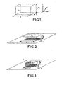
volume 33, No. 23 pages 1914 to 1916. By using the fact that, in the planes defined with constant x and z, the electric field inside a dielectric resonator type antenna in TEy 111 mode exhibits a uniform orientation and an axis of symmetry with respect to a straight line perpendicular to this orientation, it is possible to apply the theory of images and to halve the size of the DRA by effecting a cut in the plane of symmetry and by replacing the truncated half of the DRA by an infinite electric wall, namely a metallization. One thus goes from a rectangular shape of DRA represented in Figure 1 to the shapes represented in Figures 2 and 3. More specifically, the rectangular dielectric resonator type antenna of Figure 1 exhibits dimensions a, b and 2*d that have been estimated for a dielectric of permittivity sr = 12.6 operating according to the TEy 111 mode at 5.25 GHz frequency and that are such that a = 10 mm, b = 25.8 mm and 2*d = 9.6 mm. If a first electric wall is made in the plane z = 0 as represented in Figure 2, in this case the rectangular DRA exhibits dimensions b and a identical to those of the DRA of Figure 1 but a height d that is halved. Moreover, a metallization represented by thereference 1 enables an electric wall to be made in the plane z = 0. According to the embodiment of Figure 3, a second cut can be made using the symmetry of the plane z = d, and in this case one obtains an electric wall made at x = 0 by themetallization 2. Hence, the dielectric resonator exhibits dimensions equal to b/2, a, d. The size of the dielectric resonator type antenna has thus been reduced by afactor 4 with respect to its base topology. - The present invention makes it possible to reduce the dimensions of the dielectric resonator type antenna even more without degrading its radiation.
- As a consequence a subject of the present invention is a dielectric resonator antenna comprising a parallelepipedic block of dielectric material of which a first face intended to be mounted on an earth plane is covered with a first metallic layer, characterized in that at least one second face perpendicular to the first face is covered with a second metallic layer in contact with the first metallic layer over a width less than the width of the second face and over a height less than or equal to the height of the second face, so that at a given frequency, the dimensions of the dielectric resonator antenna are reduced.
- Preferably to obtain good results, the metallic layer covering the second face is centred with respect to the width of the said second face. According to another characteristic of the present invention, the metallic layer covering the second face is extended via a metallic layer covering a third face parallel to the first face. Preferably, the metallic layer covering the third face stretches over a width less than the length of the third face. According to another characteristic, the width of the metallic layer covering the third face is different from the width of the metallic layer covering the second face.
- In this case, as described hereinbelow, an even more compact DRA than the DRAs described hereinabove is obtained. The effect of reducing the size can be explained by the lengthening of the field lines inside the dielectric resonator type antenna. Specifically, new boundary conditions which deform the field lines while lengthening them are imposed on the electric field by the partial metallizations.
- Other characteristics and advantages of the present invention will become apparent on reading the description of various embodiments, this description being given with reference to the hereinappended figures in which:
- figure 1 already described is a diagrammatic perspective view of a base antenna of dielectric resonator type formed by a rectangular block;
- figure 2 already described represents a DRA in perspective of rectangular shape furnished with a metallized face shown on a wide earth plane;
- figure 3 already described is a diagrammatic perspective view of an antenna of compact dielectric resonator type on an earth plane;
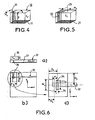
- figure 4 is a diagrammatic perspective view of an antenna of dielectric resonator type according to a first embodiment of the present invention;
- figure 5 is a view similar to that of figure 4 according to another embodiment of the present invention;
- figures 6a, 6b and 6c represent a dielectric resonator antenna fed by microstrip line;
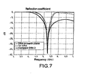
- figure 7 represents a curve giving the reflection coefficient S11 as a function of frequency for various topologies of compact DRA.
- Represented diagrammatically in perspective in Figure 4 is a first embodiment of an antenna of compact dielectric resonator type in accordance with the present invention. The dielectric resonator consists essentially of a
block 10 of dielectric material. The dielectric material which exhibits a specific permittivity sr may be a material based on ceramic or a metallizable plastic of the polyetherimide (PEI) type filled with dielectric or polypropylene (PP). In the embodiment represented, the block is of rectangular shape but it is obvious to the person skilled in the art that the block could have any other shape, in particular a square shape or even a cylindrical or polygonal shape. In a known manner, to decrease the size of the block, the lower surface intended to be laid down on a substrate with earth plane is covered with ametallic layer 11. In accordance with the present invention, one of the faces perpendicular to the face covered with themetallic layer 11 is also covered with a partialmetallic layer 12. The metallic layers are made for example from silver, chromium, nickel or with copper/nickel or copper/tin multilayers, it being possible for the deposition to be performed either by screen-printing a conducting ink in the case of a ceramic base such as alumina or by electrochemical deposition in the case of a metallizable plastic. In this case, use is preferably made of a multilayer, namely a layer of chemical copper for fastening to the plastic followed by an electrolytic copper to improve the surface state covered by a deposition of nickel or of tin to avoid any corrosion phenomenon. The metallization may also be carried out by vacuum deposition of metals of the silver, chromium, nickel type. In this case, the thickness of the depositions is close to a micron. - In the case of the block of Figure 4, the
metallization layer 12 has been deposited over the entire height of the block. - Another embodiment of the present invention will now be described with reference to Figure 5. In this case the dielectric resonator type antenna consists of a
rectangular block 20 made of a dielectric material of permittivity εr. Just as for the antenna of Figure 4, ametallic layer 21 has been deposited on theface 20 of the block. This face is mounted on the substrate with earth plane. Likewise, in accordance with the present invention, ametallic layer 22 of width less than the width of one of the vertical faces of theblock 20 has been deposited on the said face and in accordance with another characteristic of the present invention, thislayer 22 is extended via a metallic layer 23 deposited on theface 20 of the block parallel to the face carrying themetallic layer 21. As represented in Figure 5, the layer 23 exhibits a length mh less than the length of the face on which it is deposited. - To demonstrate the reduction in size of a dielectric resonator type antenna such as made according to Figures 4 and 5, a dimensioning of the various topologies has been performed on the basis of 3D electromagnetic simulation software based on the FDTD "Finite Difference Time Domain" method. An antenna of rectangular dielectric resonator type has therefore been simulated, fed through a slot via a microstrip line. This structure is represented in Figures 6a, 6b, 6c. In this case, the
block 30 furnished with metallizations just as in the case of Figure 5 is mounted on asubstrate 31. Thesubstrate 31 is a dielectric substrate of permittivity ε'r characterized by its weak RF qualities, namely exhibiting considerable dispersion in its dielectric characteristics and considerable dielectric losses. As represented in Figure 6a, the two external faces of thesubstrate 31 have been metallized, namely the upper face by alayer 32 forming an earth plane and the lower face by a layer in which themicrostrip line 33 has been etched. The DRA is fed in conventional manner through aslot 34 made in the earth plane situated on the upper surface, by themicrostrip line 33 etched on the lower face. The DRA has been dimensioned according to the various topologies described in Figures 1, 2, 3, 4 and 5 in such a way as to operate at 5.25 GHz on a substrate of type FR4 (ε'r = 4.4, h = 0.8 mm). The DRA is made in a dielectric of permittivity εr = 12.6. As represented in Figure 6b, the feed system (slot and line) is centred on the width a of the DRA: D2 = a/2. In this case, the feed line exhibits a characteristic impedance 50 Ω (wm = 1.5 mm) and the dimensions of theslot 34 are equal to wS and Ls. Themicrostrip line 33 crosses theslot 34 perpendicularly, as represented clearly in Figure 6c, with an overhang m with respect to the centre of the slot. The position of the slot is labelled via the dimension D1. For the configurations corresponding to Figures 2 and 3, the DRA is laid on an infinite earth plane while for the configuration corresponding to Figure 5, namely to one of the embodiments of the present invention, the DRA is placed at the margin of the earth plane as represented in Figure 6b. The dimensions obtained for the various configurations of DRA are given in Table 1 below.Table 1 εr=12.6 a b Height Ls ws m mv mh D1 (mm) (mm) (mm) (mm) (mm) (mm) (mm) (mm) (mm) Base DRA 10 25.8 2*d=9.6 6 2.4 3.3 0 0 0 DRA on earth plane 10 25.8 d=4.8 6 2.4 3.3 0 0 0 ½ DRA 10 12.9 d=4.8 7.5 1.2 3.6 10 0 9 DRA Figure 6 8.5 6 d=4.8 8 1.2 3 5 1.8 5.1 - As may be seen clearly, the DRA of Figure 6 exhibits a length a of 8.5 instead of a length of 10 for the other DRAs, a width b of 6 instead of widths varying between 12.9 and 25.8 and a height d equal to 4.8 instead of a height varying between 4.8 and 9.6. Therefore, with a DRA in accordance with the present invention one obtains a further reduction factor of 3 with respect to the ½ DRAs.
- More generally, the dielectric resonator type antenna is firstly dimensioned using the cutting principle along two planes of symmetry, as described in the Electronic Letters article mentioned above. Partial metallizations are deposited as described above. The partial metallizations whose dimensions depend in particular on the material used, bring about a decrease in the operating frequency of the DRA. Consequently, the dimensions a and b are adapted so as to come down to the desired frequency.
- Moreover, as represented in Figure 7 giving the reflection coefficient S11 as a function of frequency, it is seen that the DRA of Figure 5 gives an adaptation level comparable to the DRAs of Figures 3 and 4.
- The embodiments described above may be varied through embodiment alternatives. In particular, the width of the partial metallization layer of the second face may be different from the width of the metallization layer of the third face.
- With the configuration of the present invention, the size of the DRA is therefore considerably reduced while obtaining comparable performance.
Claims (5)
- Dielectric resonator antenna comprising a parallelepipedic block (10, 20) of dielectric material of which a first face intended to be mounted on an earth plane is covered with a first metallic layer (11, 21), characterized in that at least one second face perpendicular to the first face is covered with a second metallic layer (12, 22) in contact with the first metallic layer over a width less than the width of the second face and over a height less than or equal to the height of the second face, so that, for a given frequency, the dimensions of the dielectric resonator antenna are reduced.
- Antenna according to Claim 1, characterized in that the metallic layer covering the second face is centred with respect to the width of the said second face.
- Antenna according to any one of Claims 1 and 2, characterized in that the metallic layer covering the second face is extended via a metallic layer (23) covering a third face parallel to the first face.
- Antenna according to Claim 3, characterized in that the metallic layer covering the third face stretches over a width less than the length of the third face.
- Antenna according to any one of the preceding claims, characterized in that the width of the metallic layer covering the third face is different from the width of the metallic layer covering the second face.
Applications Claiming Priority (2)
| Application Number | Priority Date | Filing Date | Title |
|---|---|---|---|
| FR0211114 | 2002-09-09 | ||
| FR0211114A FR2844399A1 (en) | 2002-09-09 | 2002-09-09 | DIELECTRIC RESONATOR TYPE ANTENNAS |
Publications (2)
| Publication Number | Publication Date |
|---|---|
| EP1396907A1 EP1396907A1 (en) | 2004-03-10 |
| EP1396907B1 true EP1396907B1 (en) | 2007-01-31 |
Family
ID=31503136
Family Applications (1)
| Application Number | Title | Priority Date | Filing Date |
|---|---|---|---|
| EP03292142A Expired - Fee Related EP1396907B1 (en) | 2002-09-09 | 2003-09-01 | Dielectric resonator antenna |
Country Status (9)
| Country | Link |
|---|---|
| US (1) | US7196663B2 (en) |
| EP (1) | EP1396907B1 (en) |
| JP (1) | JP4393822B2 (en) |
| KR (1) | KR101052320B1 (en) |
| CN (1) | CN100448103C (en) |
| DE (1) | DE60311549T2 (en) |
| ES (1) | ES2280709T3 (en) |
| FR (1) | FR2844399A1 (en) |
| MX (1) | MXPA03007963A (en) |
Families Citing this family (223)
| Publication number | Priority date | Publication date | Assignee | Title |
|---|---|---|---|---|
| GB2412246B (en) * | 2004-03-16 | 2007-05-23 | Antenova Ltd | Dielectric antenna with metallised walls |
| JP5057786B2 (en) | 2006-08-09 | 2012-10-24 | 富士通株式会社 | tag |
| US7619564B2 (en) * | 2006-08-23 | 2009-11-17 | National Taiwan University | Wideband dielectric resonator monopole antenna |
| TWI324839B (en) * | 2007-05-07 | 2010-05-11 | Univ Nat Taiwan | Wideband dielectric resonator antenna and design method thereof |
| TWI345336B (en) * | 2007-10-23 | 2011-07-11 | Univ Nat Taiwan | Dielectric resonator antenna |
| TWI353686B (en) * | 2007-11-20 | 2011-12-01 | Univ Nat Taiwan | A circularly-polarized dielectric resonator antenn |
| TWI338975B (en) * | 2007-12-14 | 2011-03-11 | Univ Nat Taiwan | Circularly-polarized dielectric resonator antenna |
| TWI354399B (en) * | 2008-01-18 | 2011-12-11 | Univ Nat Taiwan | A dielectric resonator antenna with a transverse-r |
| JP4974189B2 (en) * | 2008-03-11 | 2012-07-11 | 古河電気工業株式会社 | Chip antenna and manufacturing method thereof |
| US7742001B2 (en) * | 2008-03-31 | 2010-06-22 | Tdk Corporation | Two-tier wide band antenna |
| US7800543B2 (en) * | 2008-03-31 | 2010-09-21 | Tdk Corporation | Feed-point tuned wide band antenna |
| US20090322285A1 (en) * | 2008-06-25 | 2009-12-31 | Nokia Corporation | Method and Apparatus for Wireless Charging Using a Multi-Band Antenna |
| US20100103064A1 (en) * | 2008-10-23 | 2010-04-29 | Symbol Technologies, Inc. | Parasitic dipole assisted wlan antenna |
| GB2466810A (en) | 2009-01-08 | 2010-07-14 | Visa Europe Ltd | Processing payment authorisation requests |
| US10361487B2 (en) * | 2011-07-29 | 2019-07-23 | University Of Saskatchewan | Polymer-based resonator antennas |
| US9941707B1 (en) | 2013-07-19 | 2018-04-10 | Energous Corporation | Home base station for multiple room coverage with multiple transmitters |
| US9973021B2 (en) | 2012-07-06 | 2018-05-15 | Energous Corporation | Receivers for wireless power transmission |
| US9882427B2 (en) | 2013-05-10 | 2018-01-30 | Energous Corporation | Wireless power delivery using a base station to control operations of a plurality of wireless power transmitters |
| US9853692B1 (en) | 2014-05-23 | 2017-12-26 | Energous Corporation | Systems and methods for wireless power transmission |
| US9991741B1 (en) | 2014-07-14 | 2018-06-05 | Energous Corporation | System for tracking and reporting status and usage information in a wireless power management system |
| US9871398B1 (en) | 2013-07-01 | 2018-01-16 | Energous Corporation | Hybrid charging method for wireless power transmission based on pocket-forming |
| US20140008993A1 (en) | 2012-07-06 | 2014-01-09 | DvineWave Inc. | Methodology for pocket-forming |
| US10223717B1 (en) | 2014-05-23 | 2019-03-05 | Energous Corporation | Systems and methods for payment-based authorization of wireless power transmission service |
| US10992187B2 (en) | 2012-07-06 | 2021-04-27 | Energous Corporation | System and methods of using electromagnetic waves to wirelessly deliver power to electronic devices |
| US9912199B2 (en) | 2012-07-06 | 2018-03-06 | Energous Corporation | Receivers for wireless power transmission |
| US9143000B2 (en) | 2012-07-06 | 2015-09-22 | Energous Corporation | Portable wireless charging pad |
| US9806564B2 (en) | 2014-05-07 | 2017-10-31 | Energous Corporation | Integrated rectifier and boost converter for wireless power transmission |
| US9948135B2 (en) | 2015-09-22 | 2018-04-17 | Energous Corporation | Systems and methods for identifying sensitive objects in a wireless charging transmission field |
| US9853458B1 (en) | 2014-05-07 | 2017-12-26 | Energous Corporation | Systems and methods for device and power receiver pairing |
| US9893555B1 (en) | 2013-10-10 | 2018-02-13 | Energous Corporation | Wireless charging of tools using a toolbox transmitter |
| US9252628B2 (en) | 2013-05-10 | 2016-02-02 | Energous Corporation | Laptop computer as a transmitter for wireless charging |
| US10141791B2 (en) | 2014-05-07 | 2018-11-27 | Energous Corporation | Systems and methods for controlling communications during wireless transmission of power using application programming interfaces |
| US10008889B2 (en) | 2014-08-21 | 2018-06-26 | Energous Corporation | Method for automatically testing the operational status of a wireless power receiver in a wireless power transmission system |
| US9893554B2 (en) | 2014-07-14 | 2018-02-13 | Energous Corporation | System and method for providing health safety in a wireless power transmission system |
| US10148097B1 (en) | 2013-11-08 | 2018-12-04 | Energous Corporation | Systems and methods for using a predetermined number of communication channels of a wireless power transmitter to communicate with different wireless power receivers |
| US10263432B1 (en) | 2013-06-25 | 2019-04-16 | Energous Corporation | Multi-mode transmitter with an antenna array for delivering wireless power and providing Wi-Fi access |
| US20150326070A1 (en) | 2014-05-07 | 2015-11-12 | Energous Corporation | Methods and Systems for Maximum Power Point Transfer in Receivers |
| US10186913B2 (en) | 2012-07-06 | 2019-01-22 | Energous Corporation | System and methods for pocket-forming based on constructive and destructive interferences to power one or more wireless power receivers using a wireless power transmitter including a plurality of antennas |
| US9859797B1 (en) | 2014-05-07 | 2018-01-02 | Energous Corporation | Synchronous rectifier design for wireless power receiver |
| US9939864B1 (en) | 2014-08-21 | 2018-04-10 | Energous Corporation | System and method to control a wireless power transmission system by configuration of wireless power transmission control parameters |
| US10312715B2 (en) | 2015-09-16 | 2019-06-04 | Energous Corporation | Systems and methods for wireless power charging |
| US10090699B1 (en) | 2013-11-01 | 2018-10-02 | Energous Corporation | Wireless powered house |
| US9859756B2 (en) | 2012-07-06 | 2018-01-02 | Energous Corporation | Transmittersand methods for adjusting wireless power transmission based on information from receivers |
| US9906065B2 (en) | 2012-07-06 | 2018-02-27 | Energous Corporation | Systems and methods of transmitting power transmission waves based on signals received at first and second subsets of a transmitter's antenna array |
| US9966765B1 (en) | 2013-06-25 | 2018-05-08 | Energous Corporation | Multi-mode transmitter |
| US10205239B1 (en) | 2014-05-07 | 2019-02-12 | Energous Corporation | Compact PIFA antenna |
| US9847679B2 (en) | 2014-05-07 | 2017-12-19 | Energous Corporation | System and method for controlling communication between wireless power transmitter managers |
| US10128693B2 (en) | 2014-07-14 | 2018-11-13 | Energous Corporation | System and method for providing health safety in a wireless power transmission system |
| US11502551B2 (en) | 2012-07-06 | 2022-11-15 | Energous Corporation | Wirelessly charging multiple wireless-power receivers using different subsets of an antenna array to focus energy at different locations |
| US10439448B2 (en) | 2014-08-21 | 2019-10-08 | Energous Corporation | Systems and methods for automatically testing the communication between wireless power transmitter and wireless power receiver |
| US10230266B1 (en) | 2014-02-06 | 2019-03-12 | Energous Corporation | Wireless power receivers that communicate status data indicating wireless power transmission effectiveness with a transmitter using a built-in communications component of a mobile device, and methods of use thereof |
| US10038337B1 (en) | 2013-09-16 | 2018-07-31 | Energous Corporation | Wireless power supply for rescue devices |
| US10075008B1 (en) | 2014-07-14 | 2018-09-11 | Energous Corporation | Systems and methods for manually adjusting when receiving electronic devices are scheduled to receive wirelessly delivered power from a wireless power transmitter in a wireless power network |
| US9941747B2 (en) | 2014-07-14 | 2018-04-10 | Energous Corporation | System and method for manually selecting and deselecting devices to charge in a wireless power network |
| US10211680B2 (en) | 2013-07-19 | 2019-02-19 | Energous Corporation | Method for 3 dimensional pocket-forming |
| US10206185B2 (en) | 2013-05-10 | 2019-02-12 | Energous Corporation | System and methods for wireless power transmission to an electronic device in accordance with user-defined restrictions |
| US9923386B1 (en) | 2012-07-06 | 2018-03-20 | Energous Corporation | Systems and methods for wireless power transmission by modifying a number of antenna elements used to transmit power waves to a receiver |
| US9843201B1 (en) | 2012-07-06 | 2017-12-12 | Energous Corporation | Wireless power transmitter that selects antenna sets for transmitting wireless power to a receiver based on location of the receiver, and methods of use thereof |
| US10063064B1 (en) | 2014-05-23 | 2018-08-28 | Energous Corporation | System and method for generating a power receiver identifier in a wireless power network |
| US9812890B1 (en) | 2013-07-11 | 2017-11-07 | Energous Corporation | Portable wireless charging pad |
| US9824815B2 (en) | 2013-05-10 | 2017-11-21 | Energous Corporation | Wireless charging and powering of healthcare gadgets and sensors |
| US10050462B1 (en) | 2013-08-06 | 2018-08-14 | Energous Corporation | Social power sharing for mobile devices based on pocket-forming |
| US10193396B1 (en) | 2014-05-07 | 2019-01-29 | Energous Corporation | Cluster management of transmitters in a wireless power transmission system |
| US10063106B2 (en) | 2014-05-23 | 2018-08-28 | Energous Corporation | System and method for a self-system analysis in a wireless power transmission network |
| US9876394B1 (en) | 2014-05-07 | 2018-01-23 | Energous Corporation | Boost-charger-boost system for enhanced power delivery |
| US10224982B1 (en) | 2013-07-11 | 2019-03-05 | Energous Corporation | Wireless power transmitters for transmitting wireless power and tracking whether wireless power receivers are within authorized locations |
| US9793758B2 (en) | 2014-05-23 | 2017-10-17 | Energous Corporation | Enhanced transmitter using frequency control for wireless power transmission |
| US10291066B1 (en) | 2014-05-07 | 2019-05-14 | Energous Corporation | Power transmission control systems and methods |
| US9899861B1 (en) | 2013-10-10 | 2018-02-20 | Energous Corporation | Wireless charging methods and systems for game controllers, based on pocket-forming |
| US10128699B2 (en) | 2014-07-14 | 2018-11-13 | Energous Corporation | Systems and methods of providing wireless power using receiver device sensor inputs |
| US10965164B2 (en) | 2012-07-06 | 2021-03-30 | Energous Corporation | Systems and methods of wirelessly delivering power to a receiver device |
| US9843213B2 (en) | 2013-08-06 | 2017-12-12 | Energous Corporation | Social power sharing for mobile devices based on pocket-forming |
| US10211682B2 (en) | 2014-05-07 | 2019-02-19 | Energous Corporation | Systems and methods for controlling operation of a transmitter of a wireless power network based on user instructions received from an authenticated computing device powered or charged by a receiver of the wireless power network |
| US10090886B1 (en) | 2014-07-14 | 2018-10-02 | Energous Corporation | System and method for enabling automatic charging schedules in a wireless power network to one or more devices |
| US9899873B2 (en) | 2014-05-23 | 2018-02-20 | Energous Corporation | System and method for generating a power receiver identifier in a wireless power network |
| US10218227B2 (en) | 2014-05-07 | 2019-02-26 | Energous Corporation | Compact PIFA antenna |
| US9438045B1 (en) | 2013-05-10 | 2016-09-06 | Energous Corporation | Methods and systems for maximum power point transfer in receivers |
| US10381880B2 (en) | 2014-07-21 | 2019-08-13 | Energous Corporation | Integrated antenna structure arrays for wireless power transmission |
| US10224758B2 (en) | 2013-05-10 | 2019-03-05 | Energous Corporation | Wireless powering of electronic devices with selective delivery range |
| US9876379B1 (en) | 2013-07-11 | 2018-01-23 | Energous Corporation | Wireless charging and powering of electronic devices in a vehicle |
| US10199849B1 (en) | 2014-08-21 | 2019-02-05 | Energous Corporation | Method for automatically testing the operational status of a wireless power receiver in a wireless power transmission system |
| US9838083B2 (en) | 2014-07-21 | 2017-12-05 | Energous Corporation | Systems and methods for communication with remote management systems |
| US10124754B1 (en) | 2013-07-19 | 2018-11-13 | Energous Corporation | Wireless charging and powering of electronic sensors in a vehicle |
| US9891669B2 (en) | 2014-08-21 | 2018-02-13 | Energous Corporation | Systems and methods for a configuration web service to provide configuration of a wireless power transmitter within a wireless power transmission system |
| US10199835B2 (en) | 2015-12-29 | 2019-02-05 | Energous Corporation | Radar motion detection using stepped frequency in wireless power transmission system |
| US9825674B1 (en) | 2014-05-23 | 2017-11-21 | Energous Corporation | Enhanced transmitter that selects configurations of antenna elements for performing wireless power transmission and receiving functions |
| US9831718B2 (en) | 2013-07-25 | 2017-11-28 | Energous Corporation | TV with integrated wireless power transmitter |
| US10211674B1 (en) | 2013-06-12 | 2019-02-19 | Energous Corporation | Wireless charging using selected reflectors |
| US9124125B2 (en) | 2013-05-10 | 2015-09-01 | Energous Corporation | Wireless power transmission with selective range |
| US10103582B2 (en) | 2012-07-06 | 2018-10-16 | Energous Corporation | Transmitters for wireless power transmission |
| US9954374B1 (en) | 2014-05-23 | 2018-04-24 | Energous Corporation | System and method for self-system analysis for detecting a fault in a wireless power transmission Network |
| US9887584B1 (en) | 2014-08-21 | 2018-02-06 | Energous Corporation | Systems and methods for a configuration web service to provide configuration of a wireless power transmitter within a wireless power transmission system |
| US9900057B2 (en) | 2012-07-06 | 2018-02-20 | Energous Corporation | Systems and methods for assigning groups of antenas of a wireless power transmitter to different wireless power receivers, and determining effective phases to use for wirelessly transmitting power using the assigned groups of antennas |
| US10243414B1 (en) | 2014-05-07 | 2019-03-26 | Energous Corporation | Wearable device with wireless power and payload receiver |
| US9876648B2 (en) | 2014-08-21 | 2018-01-23 | Energous Corporation | System and method to control a wireless power transmission system by configuration of wireless power transmission control parameters |
| US9847677B1 (en) | 2013-10-10 | 2017-12-19 | Energous Corporation | Wireless charging and powering of healthcare gadgets and sensors |
| US10270261B2 (en) | 2015-09-16 | 2019-04-23 | Energous Corporation | Systems and methods of object detection in wireless power charging systems |
| US10063105B2 (en) | 2013-07-11 | 2018-08-28 | Energous Corporation | Proximity transmitters for wireless power charging systems |
| US9893768B2 (en) | 2012-07-06 | 2018-02-13 | Energous Corporation | Methodology for multiple pocket-forming |
| US10291055B1 (en) | 2014-12-29 | 2019-05-14 | Energous Corporation | Systems and methods for controlling far-field wireless power transmission based on battery power levels of a receiving device |
| US10256657B2 (en) | 2015-12-24 | 2019-04-09 | Energous Corporation | Antenna having coaxial structure for near field wireless power charging |
| US10992185B2 (en) | 2012-07-06 | 2021-04-27 | Energous Corporation | Systems and methods of using electromagnetic waves to wirelessly deliver power to game controllers |
| US9887739B2 (en) | 2012-07-06 | 2018-02-06 | Energous Corporation | Systems and methods for wireless power transmission by comparing voltage levels associated with power waves transmitted by antennas of a plurality of antennas of a transmitter to determine appropriate phase adjustments for the power waves |
| US9787103B1 (en) | 2013-08-06 | 2017-10-10 | Energous Corporation | Systems and methods for wirelessly delivering power to electronic devices that are unable to communicate with a transmitter |
| US9882430B1 (en) | 2014-05-07 | 2018-01-30 | Energous Corporation | Cluster management of transmitters in a wireless power transmission system |
| US9867062B1 (en) | 2014-07-21 | 2018-01-09 | Energous Corporation | System and methods for using a remote server to authorize a receiving device that has requested wireless power and to determine whether another receiving device should request wireless power in a wireless power transmission system |
| US9941754B2 (en) | 2012-07-06 | 2018-04-10 | Energous Corporation | Wireless power transmission with selective range |
| US9368020B1 (en) | 2013-05-10 | 2016-06-14 | Energous Corporation | Off-premises alert system and method for wireless power receivers in a wireless power network |
| US9859757B1 (en) | 2013-07-25 | 2018-01-02 | Energous Corporation | Antenna tile arrangements in electronic device enclosures |
| US10141768B2 (en) | 2013-06-03 | 2018-11-27 | Energous Corporation | Systems and methods for maximizing wireless power transfer efficiency by instructing a user to change a receiver device's position |
| CN102723596A (en) * | 2012-07-12 | 2012-10-10 | Tdk大连电子有限公司 | Ultrathin small ceramic antenna |
| CN102738579A (en) * | 2012-07-12 | 2012-10-17 | Tdk大连电子有限公司 | Small-sized ceramic antenna |
| CA2899236C (en) | 2013-01-31 | 2023-02-14 | Atabak RASHIDIAN | Meta-material resonator antennas |
| US9866279B2 (en) | 2013-05-10 | 2018-01-09 | Energous Corporation | Systems and methods for selecting which power transmitter should deliver wireless power to a receiving device in a wireless power delivery network |
| US9538382B2 (en) | 2013-05-10 | 2017-01-03 | Energous Corporation | System and method for smart registration of wireless power receivers in a wireless power network |
| US9537357B2 (en) | 2013-05-10 | 2017-01-03 | Energous Corporation | Wireless sound charging methods and systems for game controllers, based on pocket-forming |
| US9419443B2 (en) | 2013-05-10 | 2016-08-16 | Energous Corporation | Transducer sound arrangement for pocket-forming |
| US9819230B2 (en) | 2014-05-07 | 2017-11-14 | Energous Corporation | Enhanced receiver for wireless power transmission |
| US10103552B1 (en) | 2013-06-03 | 2018-10-16 | Energous Corporation | Protocols for authenticated wireless power transmission |
| US10003211B1 (en) | 2013-06-17 | 2018-06-19 | Energous Corporation | Battery life of portable electronic devices |
| US10021523B2 (en) | 2013-07-11 | 2018-07-10 | Energous Corporation | Proximity transmitters for wireless power charging systems |
| US9979440B1 (en) | 2013-07-25 | 2018-05-22 | Energous Corporation | Antenna tile arrangements configured to operate as one functional unit |
| WO2015089643A1 (en) | 2013-12-20 | 2015-06-25 | Tayfeh Aligodarz Mohammadreza | Dielectric resonator antenna arrays |
| US9935482B1 (en) | 2014-02-06 | 2018-04-03 | Energous Corporation | Wireless power transmitters that transmit at determined times based on power availability and consumption at a receiving mobile device |
| US10075017B2 (en) | 2014-02-06 | 2018-09-11 | Energous Corporation | External or internal wireless power receiver with spaced-apart antenna elements for charging or powering mobile devices using wirelessly delivered power |
| US10158257B2 (en) | 2014-05-01 | 2018-12-18 | Energous Corporation | System and methods for using sound waves to wirelessly deliver power to electronic devices |
| US9966784B2 (en) | 2014-06-03 | 2018-05-08 | Energous Corporation | Systems and methods for extending battery life of portable electronic devices charged by sound |
| US10170917B1 (en) | 2014-05-07 | 2019-01-01 | Energous Corporation | Systems and methods for managing and controlling a wireless power network by establishing time intervals during which receivers communicate with a transmitter |
| US10153653B1 (en) | 2014-05-07 | 2018-12-11 | Energous Corporation | Systems and methods for using application programming interfaces to control communications between a transmitter and a receiver |
| US10153645B1 (en) | 2014-05-07 | 2018-12-11 | Energous Corporation | Systems and methods for designating a master power transmitter in a cluster of wireless power transmitters |
| US9800172B1 (en) | 2014-05-07 | 2017-10-24 | Energous Corporation | Integrated rectifier and boost converter for boosting voltage received from wireless power transmission waves |
| US9973008B1 (en) | 2014-05-07 | 2018-05-15 | Energous Corporation | Wireless power receiver with boost converters directly coupled to a storage element |
| US9876536B1 (en) | 2014-05-23 | 2018-01-23 | Energous Corporation | Systems and methods for assigning groups of antennas to transmit wireless power to different wireless power receivers |
| US10116143B1 (en) | 2014-07-21 | 2018-10-30 | Energous Corporation | Integrated antenna arrays for wireless power transmission |
| US9871301B2 (en) | 2014-07-21 | 2018-01-16 | Energous Corporation | Integrated miniature PIFA with artificial magnetic conductor metamaterials |
| US10068703B1 (en) | 2014-07-21 | 2018-09-04 | Energous Corporation | Integrated miniature PIFA with artificial magnetic conductor metamaterials |
| US9965009B1 (en) | 2014-08-21 | 2018-05-08 | Energous Corporation | Systems and methods for assigning a power receiver to individual power transmitters based on location of the power receiver |
| US9917477B1 (en) | 2014-08-21 | 2018-03-13 | Energous Corporation | Systems and methods for automatically testing the communication between power transmitter and wireless receiver |
| US10122415B2 (en) | 2014-12-27 | 2018-11-06 | Energous Corporation | Systems and methods for assigning a set of antennas of a wireless power transmitter to a wireless power receiver based on a location of the wireless power receiver |
| US9893535B2 (en) | 2015-02-13 | 2018-02-13 | Energous Corporation | Systems and methods for determining optimal charging positions to maximize efficiency of power received from wirelessly delivered sound wave energy |
| US9906275B2 (en) | 2015-09-15 | 2018-02-27 | Energous Corporation | Identifying receivers in a wireless charging transmission field |
| US10523033B2 (en) | 2015-09-15 | 2019-12-31 | Energous Corporation | Receiver devices configured to determine location within a transmission field |
| US11710321B2 (en) | 2015-09-16 | 2023-07-25 | Energous Corporation | Systems and methods of object detection in wireless power charging systems |
| US10211685B2 (en) | 2015-09-16 | 2019-02-19 | Energous Corporation | Systems and methods for real or near real time wireless communications between a wireless power transmitter and a wireless power receiver |
| US9871387B1 (en) | 2015-09-16 | 2018-01-16 | Energous Corporation | Systems and methods of object detection using one or more video cameras in wireless power charging systems |
| US10778041B2 (en) | 2015-09-16 | 2020-09-15 | Energous Corporation | Systems and methods for generating power waves in a wireless power transmission system |
| US9893538B1 (en) | 2015-09-16 | 2018-02-13 | Energous Corporation | Systems and methods of object detection in wireless power charging systems |
| US9941752B2 (en) | 2015-09-16 | 2018-04-10 | Energous Corporation | Systems and methods of object detection in wireless power charging systems |
| US10158259B1 (en) | 2015-09-16 | 2018-12-18 | Energous Corporation | Systems and methods for identifying receivers in a transmission field by transmitting exploratory power waves towards different segments of a transmission field |
| US10199850B2 (en) | 2015-09-16 | 2019-02-05 | Energous Corporation | Systems and methods for wirelessly transmitting power from a transmitter to a receiver by determining refined locations of the receiver in a segmented transmission field associated with the transmitter |
| US10186893B2 (en) | 2015-09-16 | 2019-01-22 | Energous Corporation | Systems and methods for real time or near real time wireless communications between a wireless power transmitter and a wireless power receiver |
| US10008875B1 (en) | 2015-09-16 | 2018-06-26 | Energous Corporation | Wireless power transmitter configured to transmit power waves to a predicted location of a moving wireless power receiver |
| US10135295B2 (en) | 2015-09-22 | 2018-11-20 | Energous Corporation | Systems and methods for nullifying energy levels for wireless power transmission waves |
| US10020678B1 (en) | 2015-09-22 | 2018-07-10 | Energous Corporation | Systems and methods for selecting antennas to generate and transmit power transmission waves |
| US10050470B1 (en) | 2015-09-22 | 2018-08-14 | Energous Corporation | Wireless power transmission device having antennas oriented in three dimensions |
| US10033222B1 (en) | 2015-09-22 | 2018-07-24 | Energous Corporation | Systems and methods for determining and generating a waveform for wireless power transmission waves |
| US10027168B2 (en) | 2015-09-22 | 2018-07-17 | Energous Corporation | Systems and methods for generating and transmitting wireless power transmission waves using antennas having a spacing that is selected by the transmitter |
| US10153660B1 (en) | 2015-09-22 | 2018-12-11 | Energous Corporation | Systems and methods for preconfiguring sensor data for wireless charging systems |
| US10128686B1 (en) | 2015-09-22 | 2018-11-13 | Energous Corporation | Systems and methods for identifying receiver locations using sensor technologies |
| US10135294B1 (en) | 2015-09-22 | 2018-11-20 | Energous Corporation | Systems and methods for preconfiguring transmission devices for power wave transmissions based on location data of one or more receivers |
| US10333332B1 (en) | 2015-10-13 | 2019-06-25 | Energous Corporation | Cross-polarized dipole antenna |
| US10734717B2 (en) * | 2015-10-13 | 2020-08-04 | Energous Corporation | 3D ceramic mold antenna |
| US10355361B2 (en) | 2015-10-28 | 2019-07-16 | Rogers Corporation | Dielectric resonator antenna and method of making the same |
| US11367959B2 (en) | 2015-10-28 | 2022-06-21 | Rogers Corporation | Broadband multiple layer dielectric resonator antenna and method of making the same |
| US10374315B2 (en) * | 2015-10-28 | 2019-08-06 | Rogers Corporation | Broadband multiple layer dielectric resonator antenna and method of making the same |
| US10601137B2 (en) | 2015-10-28 | 2020-03-24 | Rogers Corporation | Broadband multiple layer dielectric resonator antenna and method of making the same |
| US10476164B2 (en) | 2015-10-28 | 2019-11-12 | Rogers Corporation | Broadband multiple layer dielectric resonator antenna and method of making the same |
| US9899744B1 (en) | 2015-10-28 | 2018-02-20 | Energous Corporation | Antenna for wireless charging systems |
| US9853485B2 (en) | 2015-10-28 | 2017-12-26 | Energous Corporation | Antenna for wireless charging systems |
| US10135112B1 (en) | 2015-11-02 | 2018-11-20 | Energous Corporation | 3D antenna mount |
| US10063108B1 (en) | 2015-11-02 | 2018-08-28 | Energous Corporation | Stamped three-dimensional antenna |
| US10027180B1 (en) | 2015-11-02 | 2018-07-17 | Energous Corporation | 3D triple linear antenna that acts as heat sink |
| US10038332B1 (en) | 2015-12-24 | 2018-07-31 | Energous Corporation | Systems and methods of wireless power charging through multiple receiving devices |
| US10027159B2 (en) | 2015-12-24 | 2018-07-17 | Energous Corporation | Antenna for transmitting wireless power signals |
| US11863001B2 (en) | 2015-12-24 | 2024-01-02 | Energous Corporation | Near-field antenna for wireless power transmission with antenna elements that follow meandering patterns |
| US10256677B2 (en) | 2016-12-12 | 2019-04-09 | Energous Corporation | Near-field RF charging pad with adaptive loading to efficiently charge an electronic device at any position on the pad |
| US10079515B2 (en) | 2016-12-12 | 2018-09-18 | Energous Corporation | Near-field RF charging pad with multi-band antenna element with adaptive loading to efficiently charge an electronic device at any position on the pad |
| US10218207B2 (en) | 2015-12-24 | 2019-02-26 | Energous Corporation | Receiver chip for routing a wireless signal for wireless power charging or data reception |
| US10320446B2 (en) | 2015-12-24 | 2019-06-11 | Energous Corporation | Miniaturized highly-efficient designs for near-field power transfer system |
| US10008886B2 (en) | 2015-12-29 | 2018-06-26 | Energous Corporation | Modular antennas with heat sinks in wireless power transmission systems |
| US10923954B2 (en) | 2016-11-03 | 2021-02-16 | Energous Corporation | Wireless power receiver with a synchronous rectifier |
| KR102349607B1 (en) | 2016-12-12 | 2022-01-12 | 에너저스 코포레이션 | Methods of selectively activating antenna zones of a near-field charging pad to maximize wireless power delivered |
| US10439442B2 (en) | 2017-01-24 | 2019-10-08 | Energous Corporation | Microstrip antennas for wireless power transmitters |
| US10389161B2 (en) | 2017-03-15 | 2019-08-20 | Energous Corporation | Surface mount dielectric antennas for wireless power transmitters |
| US10680319B2 (en) | 2017-01-06 | 2020-06-09 | Energous Corporation | Devices and methods for reducing mutual coupling effects in wireless power transmission systems |
| WO2018183892A1 (en) | 2017-03-30 | 2018-10-04 | Energous Corporation | Flat antennas having two or more resonant frequencies for use in wireless power transmission systems |
| US11283189B2 (en) | 2017-05-02 | 2022-03-22 | Rogers Corporation | Connected dielectric resonator antenna array and method of making the same |
| US11876295B2 (en) | 2017-05-02 | 2024-01-16 | Rogers Corporation | Electromagnetic reflector for use in a dielectric resonator antenna system |
| US10511097B2 (en) | 2017-05-12 | 2019-12-17 | Energous Corporation | Near-field antennas for accumulating energy at a near-field distance with minimal far-field gain |
| US11462949B2 (en) | 2017-05-16 | 2022-10-04 | Wireless electrical Grid LAN, WiGL Inc | Wireless charging method and system |
| KR102312067B1 (en) | 2017-06-07 | 2021-10-13 | 로저스코포레이션 | Dielectric Resonator Antenna System |
| US10848853B2 (en) | 2017-06-23 | 2020-11-24 | Energous Corporation | Systems, methods, and devices for utilizing a wire of a sound-producing device as an antenna for receipt of wirelessly delivered power |
| US10122219B1 (en) | 2017-10-10 | 2018-11-06 | Energous Corporation | Systems, methods, and devices for using a battery as a antenna for receiving wirelessly delivered power from radio frequency power waves |
| US11342798B2 (en) | 2017-10-30 | 2022-05-24 | Energous Corporation | Systems and methods for managing coexistence of wireless-power signals and data signals operating in a same frequency band |
| US11616302B2 (en) | 2018-01-15 | 2023-03-28 | Rogers Corporation | Dielectric resonator antenna having first and second dielectric portions |
| US10910722B2 (en) | 2018-01-15 | 2021-02-02 | Rogers Corporation | Dielectric resonator antenna having first and second dielectric portions |
| US10892544B2 (en) | 2018-01-15 | 2021-01-12 | Rogers Corporation | Dielectric resonator antenna having first and second dielectric portions |
| US10615647B2 (en) | 2018-02-02 | 2020-04-07 | Energous Corporation | Systems and methods for detecting wireless power receivers and other objects at a near-field charging pad |
| US11159057B2 (en) | 2018-03-14 | 2021-10-26 | Energous Corporation | Loop antennas with selectively-activated feeds to control propagation patterns of wireless power signals |
| EP3584885A1 (en) * | 2018-06-19 | 2019-12-25 | Premix Oy | Resonator-based leaky-wave structure |
| US11515732B2 (en) | 2018-06-25 | 2022-11-29 | Energous Corporation | Power wave transmission techniques to focus wirelessly delivered power at a receiving device |
| US11552390B2 (en) | 2018-09-11 | 2023-01-10 | Rogers Corporation | Dielectric resonator antenna system |
| CN109193147B (en) * | 2018-09-14 | 2020-09-08 | 南通大学 | Low-profile filtering antenna adopting grooved dielectric patch |
| US11437735B2 (en) | 2018-11-14 | 2022-09-06 | Energous Corporation | Systems for receiving electromagnetic energy using antennas that are minimally affected by the presence of the human body |
| CN109560385B (en) * | 2018-11-26 | 2021-02-05 | 广东三水合肥工业大学研究院 | Broadband ceramic antenna with seamless metal sleeve |
| US11031697B2 (en) | 2018-11-29 | 2021-06-08 | Rogers Corporation | Electromagnetic device |
| US11637377B2 (en) | 2018-12-04 | 2023-04-25 | Rogers Corporation | Dielectric electromagnetic structure and method of making the same |
| CN109687112A (en) * | 2019-01-22 | 2019-04-26 | 南通大学 | A kind of miniaturization dielectric patch antenna |
| KR20210117283A (en) | 2019-01-28 | 2021-09-28 | 에너저스 코포레이션 | Systems and methods for a small antenna for wireless power transmission |
| JP2022519749A (en) | 2019-02-06 | 2022-03-24 | エナージャス コーポレイション | Systems and methods for estimating the optimum phase for use with individual antennas in an antenna array |
| CN109950695B (en) * | 2019-02-28 | 2024-03-22 | 禾邦电子(苏州)有限公司 | Communication equipment and method for realizing 5G mobile communication |
| WO2020248289A1 (en) * | 2019-06-14 | 2020-12-17 | Nokia Shanghai Bell Co., Ltd. | Dielectric resonator antenna and dielectric resonator antenna array |
| CN110247186B (en) * | 2019-06-21 | 2021-01-01 | 西安电子科技大学 | Wide-beam dielectric resonator antenna |
| WO2021055898A1 (en) | 2019-09-20 | 2021-03-25 | Energous Corporation | Systems and methods for machine learning based foreign object detection for wireless power transmission |
| EP4032169A4 (en) | 2019-09-20 | 2023-12-06 | Energous Corporation | Classifying and detecting foreign objects using a power amplifier controller integrated circuit in wireless power transmission systems |
| WO2021055899A1 (en) | 2019-09-20 | 2021-03-25 | Energous Corporation | Systems and methods of protecting wireless power receivers using multiple rectifiers and establishing in-band communications using multiple rectifiers |
| US11381118B2 (en) | 2019-09-20 | 2022-07-05 | Energous Corporation | Systems and methods for machine learning based foreign object detection for wireless power transmission |
| WO2021119483A1 (en) | 2019-12-13 | 2021-06-17 | Energous Corporation | Charging pad with guiding contours to align an electronic device on the charging pad and efficiently transfer near-field radio-frequency energy to the electronic device |
| US10985617B1 (en) | 2019-12-31 | 2021-04-20 | Energous Corporation | System for wirelessly transmitting energy at a near-field distance without using beam-forming control |
| US11482790B2 (en) | 2020-04-08 | 2022-10-25 | Rogers Corporation | Dielectric lens and electromagnetic device with same |
| US11799324B2 (en) | 2020-04-13 | 2023-10-24 | Energous Corporation | Wireless-power transmitting device for creating a uniform near-field charging area |
| US20220013915A1 (en) * | 2020-07-08 | 2022-01-13 | Samsung Electro-Mechanics Co., Ltd. | Multilayer dielectric resonator antenna and antenna module |
| US11916398B2 (en) | 2021-12-29 | 2024-02-27 | Energous Corporation | Small form-factor devices with integrated and modular harvesting receivers, and shelving-mounted wireless-power transmitters for use therewith |
Family Cites Families (11)
| Publication number | Priority date | Publication date | Assignee | Title |
|---|---|---|---|---|
| US632382A (en) * | 1899-04-14 | 1899-09-05 | Aaron M Weber | Skirt-binder. |
| US6198450B1 (en) * | 1995-06-20 | 2001-03-06 | Naoki Adachi | Dielectric resonator antenna for a mobile communication |
| JP3279188B2 (en) * | 1996-07-17 | 2002-04-30 | 株式会社村田製作所 | Surface mount antenna |
| DE19837266A1 (en) * | 1998-08-17 | 2000-02-24 | Philips Corp Intellectual Pty | Dielectric resonator antenna |
| DE19858790A1 (en) * | 1998-12-18 | 2000-06-21 | Philips Corp Intellectual Pty | Dielectric resonator antenna uses metallization of electric field symmetry planes to achieve reduced size |
| FR2797352B1 (en) * | 1999-08-05 | 2007-04-20 | Cit Alcatel | STORED ANTENNA OF RESONANT STRUCTURES AND MULTIFREQUENCY RADIOCOMMUNICATION DEVICE INCLUDING THE ANTENNA |
| JP2001203513A (en) * | 2000-01-21 | 2001-07-27 | Tdk Corp | High frequency dielectric resonator |
| JP3494109B2 (en) * | 2000-03-13 | 2004-02-03 | Tdk株式会社 | Bandpass filter using TEM mode dielectric resonator |
| US6621381B1 (en) * | 2000-01-21 | 2003-09-16 | Tdk Corporation | TEM-mode dielectric resonator and bandpass filter using the resonator |
| JP2002141738A (en) * | 2000-10-30 | 2002-05-17 | Yokowo Co Ltd | Dielectric antenna and adjustment method for its resonance frequency |
| KR100444217B1 (en) * | 2001-09-12 | 2004-08-16 | 삼성전기주식회사 | Surface mounted chip antenna |
-
2002
- 2002-09-09 FR FR0211114A patent/FR2844399A1/en active Pending
-
2003
- 2003-09-01 DE DE60311549T patent/DE60311549T2/en not_active Expired - Lifetime
- 2003-09-01 ES ES03292142T patent/ES2280709T3/en not_active Expired - Lifetime
- 2003-09-01 EP EP03292142A patent/EP1396907B1/en not_active Expired - Fee Related
- 2003-09-02 KR KR1020030061067A patent/KR101052320B1/en not_active IP Right Cessation
- 2003-09-04 MX MXPA03007963A patent/MXPA03007963A/en active IP Right Grant
- 2003-09-08 JP JP2003315339A patent/JP4393822B2/en not_active Expired - Fee Related
- 2003-09-08 CN CNB031470920A patent/CN100448103C/en not_active Expired - Fee Related
- 2003-09-09 US US10/659,653 patent/US7196663B2/en not_active Expired - Fee Related
Also Published As
| Publication number | Publication date |
|---|---|
| ES2280709T3 (en) | 2007-09-16 |
| MXPA03007963A (en) | 2004-10-15 |
| US20040130489A1 (en) | 2004-07-08 |
| DE60311549D1 (en) | 2007-03-22 |
| JP2004104792A (en) | 2004-04-02 |
| CN1495967A (en) | 2004-05-12 |
| KR20040023521A (en) | 2004-03-18 |
| US7196663B2 (en) | 2007-03-27 |
| KR101052320B1 (en) | 2011-07-27 |
| CN100448103C (en) | 2008-12-31 |
| FR2844399A1 (en) | 2004-03-12 |
| EP1396907A1 (en) | 2004-03-10 |
| JP4393822B2 (en) | 2010-01-06 |
| DE60311549T2 (en) | 2007-10-31 |
Similar Documents
| Publication | Publication Date | Title |
|---|---|---|
| EP1396907B1 (en) | Dielectric resonator antenna | |
| KR100969984B1 (en) | Dielectric resonator wideband antenna | |
| US6323824B1 (en) | Dielectric resonator antenna | |
| JP3296276B2 (en) | Chip antenna | |
| JP3738577B2 (en) | ANTENNA DEVICE AND MOBILE COMMUNICATION DEVICE | |
| EP0765001B1 (en) | Chip antenna | |
| US5621366A (en) | High-Q multi-layer ceramic RF transmission line resonator | |
| JPH10145123A (en) | Meander line antenna | |
| JP2003204209A (en) | Wiring board for high frequency | |
| JPH0955618A (en) | Chip antenna | |
| US20050001770A1 (en) | Antenna, antenna module and radio communication apparatus provided with the same | |
| AU3859099A (en) | Broad band patch antenna | |
| EP0828310B1 (en) | Antenna device | |
| JP2009182786A (en) | Laminated antenna | |
| JP4206325B2 (en) | antenna | |
| JP3513081B2 (en) | Connection structure and frequency adjustment method in the connection structure | |
| WO2020260747A1 (en) | A capacitor structure and a chip antenna | |
| JPH10335927A (en) | Antenna substrate | |
| JP4017137B2 (en) | ANTENNA ELEMENT AND RADIO COMMUNICATION DEVICE USING THE SAME | |
| JPH10242734A (en) | Chip antenna | |
| Lee et al. | Multi-layer dual-band microstrip antenna | |
| CN111710994A (en) | Thin 5G and next generation mobile terminal oriented broadband millimeter wave antenna array | |
| JP2011109450A (en) | Bandpass filter, and electronic apparatus using the same | |
| JP2004112394A (en) | Microstrip antenna and radio communication apparatus using it | |
| KYI | Design and fabrication of multi-fingered lines and antenna |
Legal Events
| Date | Code | Title | Description |
|---|---|---|---|
| PUAI | Public reference made under article 153(3) epc to a published international application that has entered the european phase |
Free format text: ORIGINAL CODE: 0009012 |
|
| AK | Designated contracting states |
Kind code of ref document: A1 Designated state(s): AT BE BG CH CY CZ DE DK EE ES FI FR GB GR HU IE IT LI LU MC NL PT RO SE SI SK TR |
|
| AX | Request for extension of the european patent |
Extension state: AL LT LV MK |
|
| 17P | Request for examination filed |
Effective date: 20040902 |
|
| AKX | Designation fees paid |
Designated state(s): DE ES FR GB IT |
|
| 17Q | First examination report despatched |
Effective date: 20050615 |
|
| RAP1 | Party data changed (applicant data changed or rights of an application transferred) |
Owner name: THOMSON LICENSING |
|
| GRAP | Despatch of communication of intention to grant a patent |
Free format text: ORIGINAL CODE: EPIDOSNIGR1 |
|
| GRAS | Grant fee paid |
Free format text: ORIGINAL CODE: EPIDOSNIGR3 |
|
| GRAA | (expected) grant |
Free format text: ORIGINAL CODE: 0009210 |
|
| AK | Designated contracting states |
Kind code of ref document: B1 Designated state(s): DE ES FR GB IT |
|
| REG | Reference to a national code |
Ref country code: GB Ref legal event code: FG4D |
|
| RIN1 | Information on inventor provided before grant (corrected) |
Inventor name: LE BOLZER, FRANCOISE Inventor name: NICOLAS, CORINNE Inventor name: CORMOS, DELIA Inventor name: LAISNE, ALEXANDRE Inventor name: GILLARD, RAPHAEL |
|
| REF | Corresponds to: |
Ref document number: 60311549 Country of ref document: DE Date of ref document: 20070322 Kind code of ref document: P |
|
| ET | Fr: translation filed | ||
| REG | Reference to a national code |
Ref country code: ES Ref legal event code: FG2A Ref document number: 2280709 Country of ref document: ES Kind code of ref document: T3 |
|
| PLBE | No opposition filed within time limit |
Free format text: ORIGINAL CODE: 0009261 |
|
| STAA | Information on the status of an ep patent application or granted ep patent |
Free format text: STATUS: NO OPPOSITION FILED WITHIN TIME LIMIT |
|
| 26N | No opposition filed |
Effective date: 20071101 |
|
| REG | Reference to a national code |
Ref country code: FR Ref legal event code: PLFP Year of fee payment: 13 |
|
| PGFP | Annual fee paid to national office [announced via postgrant information from national office to epo] |
Ref country code: GB Payment date: 20150924 Year of fee payment: 13 Ref country code: ES Payment date: 20150810 Year of fee payment: 13 Ref country code: DE Payment date: 20150924 Year of fee payment: 13 |
|
| PGFP | Annual fee paid to national office [announced via postgrant information from national office to epo] |
Ref country code: FR Payment date: 20150917 Year of fee payment: 13 |
|
| PGFP | Annual fee paid to national office [announced via postgrant information from national office to epo] |
Ref country code: IT Payment date: 20150925 Year of fee payment: 13 |
|
| REG | Reference to a national code |
Ref country code: DE Ref legal event code: R119 Ref document number: 60311549 Country of ref document: DE |
|
| GBPC | Gb: european patent ceased through non-payment of renewal fee |
Effective date: 20160901 |
|
| REG | Reference to a national code |
Ref country code: FR Ref legal event code: ST Effective date: 20170531 |
|
| PG25 | Lapsed in a contracting state [announced via postgrant information from national office to epo] |
Ref country code: DE Free format text: LAPSE BECAUSE OF NON-PAYMENT OF DUE FEES Effective date: 20170401 Ref country code: GB Free format text: LAPSE BECAUSE OF NON-PAYMENT OF DUE FEES Effective date: 20160901 Ref country code: FR Free format text: LAPSE BECAUSE OF NON-PAYMENT OF DUE FEES Effective date: 20160930 |
|
| PG25 | Lapsed in a contracting state [announced via postgrant information from national office to epo] |
Ref country code: IT Free format text: LAPSE BECAUSE OF NON-PAYMENT OF DUE FEES Effective date: 20160901 |
|
| PG25 | Lapsed in a contracting state [announced via postgrant information from national office to epo] |
Ref country code: ES Free format text: LAPSE BECAUSE OF NON-PAYMENT OF DUE FEES Effective date: 20160902 |
|
| REG | Reference to a national code |
Ref country code: ES Ref legal event code: FD2A Effective date: 20181128 |