EP1396868A1 - Method and device for machining stacked core - Google Patents
Method and device for machining stacked core Download PDFInfo
- Publication number
- EP1396868A1 EP1396868A1 EP02733443A EP02733443A EP1396868A1 EP 1396868 A1 EP1396868 A1 EP 1396868A1 EP 02733443 A EP02733443 A EP 02733443A EP 02733443 A EP02733443 A EP 02733443A EP 1396868 A1 EP1396868 A1 EP 1396868A1
- Authority
- EP
- European Patent Office
- Prior art keywords
- time
- period
- press machine
- angle indexing
- rotating
- Prior art date
- Legal status (The legal status is an assumption and is not a legal conclusion. Google has not performed a legal analysis and makes no representation as to the accuracy of the status listed.)
- Granted
Links
Images




Classifications
-
- H—ELECTRICITY
- H01—ELECTRIC ELEMENTS
- H01F—MAGNETS; INDUCTANCES; TRANSFORMERS; SELECTION OF MATERIALS FOR THEIR MAGNETIC PROPERTIES
- H01F41/00—Apparatus or processes specially adapted for manufacturing or assembling magnets, inductances or transformers; Apparatus or processes specially adapted for manufacturing materials characterised by their magnetic properties
- H01F41/02—Apparatus or processes specially adapted for manufacturing or assembling magnets, inductances or transformers; Apparatus or processes specially adapted for manufacturing materials characterised by their magnetic properties for manufacturing cores, coils, or magnets
-
- H—ELECTRICITY
- H02—GENERATION; CONVERSION OR DISTRIBUTION OF ELECTRIC POWER
- H02K—DYNAMO-ELECTRIC MACHINES
- H02K15/00—Processes or apparatus specially adapted for manufacturing, assembling, maintaining or repairing of dynamo-electric machines
- H02K15/02—Processes or apparatus specially adapted for manufacturing, assembling, maintaining or repairing of dynamo-electric machines of stator or rotor bodies
-
- H—ELECTRICITY
- H01—ELECTRIC ELEMENTS
- H01F—MAGNETS; INDUCTANCES; TRANSFORMERS; SELECTION OF MATERIALS FOR THEIR MAGNETIC PROPERTIES
- H01F41/00—Apparatus or processes specially adapted for manufacturing or assembling magnets, inductances or transformers; Apparatus or processes specially adapted for manufacturing materials characterised by their magnetic properties
- H01F41/02—Apparatus or processes specially adapted for manufacturing or assembling magnets, inductances or transformers; Apparatus or processes specially adapted for manufacturing materials characterised by their magnetic properties for manufacturing cores, coils, or magnets
- H01F41/0206—Manufacturing of magnetic cores by mechanical means
- H01F41/0213—Manufacturing of magnetic circuits made from strip(s) or ribbon(s)
-
- H—ELECTRICITY
- H01—ELECTRIC ELEMENTS
- H01F—MAGNETS; INDUCTANCES; TRANSFORMERS; SELECTION OF MATERIALS FOR THEIR MAGNETIC PROPERTIES
- H01F41/00—Apparatus or processes specially adapted for manufacturing or assembling magnets, inductances or transformers; Apparatus or processes specially adapted for manufacturing materials characterised by their magnetic properties
- H01F41/02—Apparatus or processes specially adapted for manufacturing or assembling magnets, inductances or transformers; Apparatus or processes specially adapted for manufacturing materials characterised by their magnetic properties for manufacturing cores, coils, or magnets
- H01F41/0206—Manufacturing of magnetic cores by mechanical means
- H01F41/0233—Manufacturing of magnetic circuits made from sheets
-
- Y—GENERAL TAGGING OF NEW TECHNOLOGICAL DEVELOPMENTS; GENERAL TAGGING OF CROSS-SECTIONAL TECHNOLOGIES SPANNING OVER SEVERAL SECTIONS OF THE IPC; TECHNICAL SUBJECTS COVERED BY FORMER USPC CROSS-REFERENCE ART COLLECTIONS [XRACs] AND DIGESTS
- Y02—TECHNOLOGIES OR APPLICATIONS FOR MITIGATION OR ADAPTATION AGAINST CLIMATE CHANGE
- Y02E—REDUCTION OF GREENHOUSE GAS [GHG] EMISSIONS, RELATED TO ENERGY GENERATION, TRANSMISSION OR DISTRIBUTION
- Y02E60/00—Enabling technologies; Technologies with a potential or indirect contribution to GHG emissions mitigation
- Y02E60/10—Energy storage using batteries
-
- Y—GENERAL TAGGING OF NEW TECHNOLOGICAL DEVELOPMENTS; GENERAL TAGGING OF CROSS-SECTIONAL TECHNOLOGIES SPANNING OVER SEVERAL SECTIONS OF THE IPC; TECHNICAL SUBJECTS COVERED BY FORMER USPC CROSS-REFERENCE ART COLLECTIONS [XRACs] AND DIGESTS
- Y02—TECHNOLOGIES OR APPLICATIONS FOR MITIGATION OR ADAPTATION AGAINST CLIMATE CHANGE
- Y02P—CLIMATE CHANGE MITIGATION TECHNOLOGIES IN THE PRODUCTION OR PROCESSING OF GOODS
- Y02P70/00—Climate change mitigation technologies in the production process for final industrial or consumer products
- Y02P70/50—Manufacturing or production processes characterised by the final manufactured product
-
- Y—GENERAL TAGGING OF NEW TECHNOLOGICAL DEVELOPMENTS; GENERAL TAGGING OF CROSS-SECTIONAL TECHNOLOGIES SPANNING OVER SEVERAL SECTIONS OF THE IPC; TECHNICAL SUBJECTS COVERED BY FORMER USPC CROSS-REFERENCE ART COLLECTIONS [XRACs] AND DIGESTS
- Y10—TECHNICAL SUBJECTS COVERED BY FORMER USPC
- Y10T—TECHNICAL SUBJECTS COVERED BY FORMER US CLASSIFICATION
- Y10T29/00—Metal working
- Y10T29/49—Method of mechanical manufacture
- Y10T29/49002—Electrical device making
- Y10T29/49004—Electrical device making including measuring or testing of device or component part
-
- Y—GENERAL TAGGING OF NEW TECHNOLOGICAL DEVELOPMENTS; GENERAL TAGGING OF CROSS-SECTIONAL TECHNOLOGIES SPANNING OVER SEVERAL SECTIONS OF THE IPC; TECHNICAL SUBJECTS COVERED BY FORMER USPC CROSS-REFERENCE ART COLLECTIONS [XRACs] AND DIGESTS
- Y10—TECHNICAL SUBJECTS COVERED BY FORMER USPC
- Y10T—TECHNICAL SUBJECTS COVERED BY FORMER US CLASSIFICATION
- Y10T29/00—Metal working
- Y10T29/49—Method of mechanical manufacture
- Y10T29/49002—Electrical device making
- Y10T29/49009—Dynamoelectric machine
-
- Y—GENERAL TAGGING OF NEW TECHNOLOGICAL DEVELOPMENTS; GENERAL TAGGING OF CROSS-SECTIONAL TECHNOLOGIES SPANNING OVER SEVERAL SECTIONS OF THE IPC; TECHNICAL SUBJECTS COVERED BY FORMER USPC CROSS-REFERENCE ART COLLECTIONS [XRACs] AND DIGESTS
- Y10—TECHNICAL SUBJECTS COVERED BY FORMER USPC
- Y10T—TECHNICAL SUBJECTS COVERED BY FORMER US CLASSIFICATION
- Y10T29/00—Metal working
- Y10T29/49—Method of mechanical manufacture
- Y10T29/49002—Electrical device making
- Y10T29/49009—Dynamoelectric machine
- Y10T29/49012—Rotor
-
- Y—GENERAL TAGGING OF NEW TECHNOLOGICAL DEVELOPMENTS; GENERAL TAGGING OF CROSS-SECTIONAL TECHNOLOGIES SPANNING OVER SEVERAL SECTIONS OF THE IPC; TECHNICAL SUBJECTS COVERED BY FORMER USPC CROSS-REFERENCE ART COLLECTIONS [XRACs] AND DIGESTS
- Y10—TECHNICAL SUBJECTS COVERED BY FORMER USPC
- Y10T—TECHNICAL SUBJECTS COVERED BY FORMER US CLASSIFICATION
- Y10T29/00—Metal working
- Y10T29/49—Method of mechanical manufacture
- Y10T29/49002—Electrical device making
- Y10T29/4902—Electromagnet, transformer or inductor
- Y10T29/49069—Data storage inductor or core
-
- Y—GENERAL TAGGING OF NEW TECHNOLOGICAL DEVELOPMENTS; GENERAL TAGGING OF CROSS-SECTIONAL TECHNOLOGIES SPANNING OVER SEVERAL SECTIONS OF THE IPC; TECHNICAL SUBJECTS COVERED BY FORMER USPC CROSS-REFERENCE ART COLLECTIONS [XRACs] AND DIGESTS
- Y10—TECHNICAL SUBJECTS COVERED BY FORMER USPC
- Y10T—TECHNICAL SUBJECTS COVERED BY FORMER US CLASSIFICATION
- Y10T29/00—Metal working
- Y10T29/49—Method of mechanical manufacture
- Y10T29/49002—Electrical device making
- Y10T29/4902—Electromagnet, transformer or inductor
- Y10T29/49075—Electromagnet, transformer or inductor including permanent magnet or core
-
- Y—GENERAL TAGGING OF NEW TECHNOLOGICAL DEVELOPMENTS; GENERAL TAGGING OF CROSS-SECTIONAL TECHNOLOGIES SPANNING OVER SEVERAL SECTIONS OF THE IPC; TECHNICAL SUBJECTS COVERED BY FORMER USPC CROSS-REFERENCE ART COLLECTIONS [XRACs] AND DIGESTS
- Y10—TECHNICAL SUBJECTS COVERED BY FORMER USPC
- Y10T—TECHNICAL SUBJECTS COVERED BY FORMER US CLASSIFICATION
- Y10T29/00—Metal working
- Y10T29/49—Method of mechanical manufacture
- Y10T29/49002—Electrical device making
- Y10T29/4902—Electromagnet, transformer or inductor
- Y10T29/49075—Electromagnet, transformer or inductor including permanent magnet or core
- Y10T29/49078—Laminated
-
- Y—GENERAL TAGGING OF NEW TECHNOLOGICAL DEVELOPMENTS; GENERAL TAGGING OF CROSS-SECTIONAL TECHNOLOGIES SPANNING OVER SEVERAL SECTIONS OF THE IPC; TECHNICAL SUBJECTS COVERED BY FORMER USPC CROSS-REFERENCE ART COLLECTIONS [XRACs] AND DIGESTS
- Y10—TECHNICAL SUBJECTS COVERED BY FORMER USPC
- Y10T—TECHNICAL SUBJECTS COVERED BY FORMER US CLASSIFICATION
- Y10T29/00—Metal working
- Y10T29/49—Method of mechanical manufacture
- Y10T29/49229—Prime mover or fluid pump making
- Y10T29/49236—Fluid pump or compressor making
- Y10T29/4924—Scroll or peristaltic type
-
- Y—GENERAL TAGGING OF NEW TECHNOLOGICAL DEVELOPMENTS; GENERAL TAGGING OF CROSS-SECTIONAL TECHNOLOGIES SPANNING OVER SEVERAL SECTIONS OF THE IPC; TECHNICAL SUBJECTS COVERED BY FORMER USPC CROSS-REFERENCE ART COLLECTIONS [XRACs] AND DIGESTS
- Y10—TECHNICAL SUBJECTS COVERED BY FORMER USPC
- Y10T—TECHNICAL SUBJECTS COVERED BY FORMER US CLASSIFICATION
- Y10T29/00—Metal working
- Y10T29/49—Method of mechanical manufacture
- Y10T29/49764—Method of mechanical manufacture with testing or indicating
- Y10T29/49778—Method of mechanical manufacture with testing or indicating with aligning, guiding, or instruction
- Y10T29/4978—Assisting assembly or disassembly
-
- Y—GENERAL TAGGING OF NEW TECHNOLOGICAL DEVELOPMENTS; GENERAL TAGGING OF CROSS-SECTIONAL TECHNOLOGIES SPANNING OVER SEVERAL SECTIONS OF THE IPC; TECHNICAL SUBJECTS COVERED BY FORMER USPC CROSS-REFERENCE ART COLLECTIONS [XRACs] AND DIGESTS
- Y10—TECHNICAL SUBJECTS COVERED BY FORMER USPC
- Y10T—TECHNICAL SUBJECTS COVERED BY FORMER US CLASSIFICATION
- Y10T29/00—Metal working
- Y10T29/51—Plural diverse manufacturing apparatus including means for metal shaping or assembling
- Y10T29/5136—Separate tool stations for selective or successive operation on work
- Y10T29/5137—Separate tool stations for selective or successive operation on work including assembling or disassembling station
- Y10T29/5142—Separate tool stations for selective or successive operation on work including assembling or disassembling station and means to sever work from supply
-
- Y—GENERAL TAGGING OF NEW TECHNOLOGICAL DEVELOPMENTS; GENERAL TAGGING OF CROSS-SECTIONAL TECHNOLOGIES SPANNING OVER SEVERAL SECTIONS OF THE IPC; TECHNICAL SUBJECTS COVERED BY FORMER USPC CROSS-REFERENCE ART COLLECTIONS [XRACs] AND DIGESTS
- Y10—TECHNICAL SUBJECTS COVERED BY FORMER USPC
- Y10T—TECHNICAL SUBJECTS COVERED BY FORMER US CLASSIFICATION
- Y10T29/00—Metal working
- Y10T29/53—Means to assemble or disassemble
- Y10T29/5313—Means to assemble electrical device
- Y10T29/53143—Motor or generator
-
- Y—GENERAL TAGGING OF NEW TECHNOLOGICAL DEVELOPMENTS; GENERAL TAGGING OF CROSS-SECTIONAL TECHNOLOGIES SPANNING OVER SEVERAL SECTIONS OF THE IPC; TECHNICAL SUBJECTS COVERED BY FORMER USPC CROSS-REFERENCE ART COLLECTIONS [XRACs] AND DIGESTS
- Y10—TECHNICAL SUBJECTS COVERED BY FORMER USPC
- Y10T—TECHNICAL SUBJECTS COVERED BY FORMER US CLASSIFICATION
- Y10T29/00—Metal working
- Y10T29/53—Means to assemble or disassemble
- Y10T29/5313—Means to assemble electrical device
- Y10T29/5317—Laminated device
-
- Y—GENERAL TAGGING OF NEW TECHNOLOGICAL DEVELOPMENTS; GENERAL TAGGING OF CROSS-SECTIONAL TECHNOLOGIES SPANNING OVER SEVERAL SECTIONS OF THE IPC; TECHNICAL SUBJECTS COVERED BY FORMER USPC CROSS-REFERENCE ART COLLECTIONS [XRACs] AND DIGESTS
- Y10—TECHNICAL SUBJECTS COVERED BY FORMER USPC
- Y10T—TECHNICAL SUBJECTS COVERED BY FORMER US CLASSIFICATION
- Y10T83/00—Cutting
- Y10T83/04—Processes
- Y10T83/0448—With subsequent handling [i.e., of product]
-
- Y—GENERAL TAGGING OF NEW TECHNOLOGICAL DEVELOPMENTS; GENERAL TAGGING OF CROSS-SECTIONAL TECHNOLOGIES SPANNING OVER SEVERAL SECTIONS OF THE IPC; TECHNICAL SUBJECTS COVERED BY FORMER USPC CROSS-REFERENCE ART COLLECTIONS [XRACs] AND DIGESTS
- Y10—TECHNICAL SUBJECTS COVERED BY FORMER USPC
- Y10T—TECHNICAL SUBJECTS COVERED BY FORMER US CLASSIFICATION
- Y10T83/00—Cutting
- Y10T83/202—With product handling means
- Y10T83/2092—Means to move, guide, or permit free fall or flight of product
Definitions
- the present invention relates to a stacked core assembly method and its apparatus, which stacks a thin-strip material while forwardly feeding it, and more particularly, to a stacked core assembly method and its apparatus, in which a stacked member is rotatable in a die in a stacked cavity.
- a stacked core for example, a motor stacked core is formed in the following manner.
- a thin-strip material intermittent carried into a press die by a feeder by means of the thin-strip material intermittent proceeding through a plurality of pressing and/or punching process cavities of the press die, mounted to a press machine.
- a thin-sheet plate is then constantly intermittent stacked to a prior stacked member immediately after being punched out from the thin-strip material as a sheet of plate, pressed and interlocked to the prior stacked member in the stacking cavity of the press die.
- a thickness of the each punched out thin-sheet of plate vary within itself, due to prior pressing and/or punching processes, as a conventional method, rotate in a predetermined angle a stacking cavity device, a block having the stacking cavity and rotates in the press die.
- the thin-sheet of plate is interlocked to the prior stacked member with pressure. Thereafter, a thickness of the stacked core is within a predetermined thickness.
- An equipment of angle indexing apparatus for driving the stacking cavity device in the predetermined angle is set to the press machine, which is driven by continuous rotational power, transmitted from the driving unit of the press machine.
- the angle indexing apparatus is driven for rotating the stacking cavity device during a Feeding-Phase period of time (by means of a Crank Angle from 270° to 90°) of the press machine as well as the thin-strip material is carried to next pressing and/or punching process cavity.
- the angle indexing apparatus completes rotating the stacking cavity device (by means of the Crank Angle at 90° of the press machine )
- the press machine starts its Machining-Phase and runs in to a Machining-Phase period of time (by means of the Crank Angle from 90 ° to 270 °) of the press machine.
- neither the angle indexing apparatus drives stacking cavity device nor is the thin-strip material carried to next process cavity.
- the thin-strip material at each cavity is pressed/punched and at the stacking cavity, a thin-sheet of plate is punched out from the thin-strip material, pressed and interlocked to the prior stacked member.
- the angle indexing apparatus is set as to rotate at in the Feeding-Phase period of the press machine, includes a cam unit having a cam driven by an input shaft, and an indexing unit having an output shaft and a plurality of cam rollers contacted to the cam unit.
- a cam unit having a cam driven by an input shaft
- an indexing unit having an output shaft and a plurality of cam rollers contacted to the cam unit.
- an input shaft of an angle indexing apparatus is connected to a driving unit of a press machine by a transmission member.
- the input shaft of the angle indexing apparatus continuously rotates at a constant rotational speed, synchronized to a constant rotational speed of the driving unit of the press machine.
- the output shaft of the angle indexing apparatus has been equally intermittent driven synchronized to the Feeding-Phase period of the press machine, by means of the output shaft of the angle indexing apparatus rotates in the predetermined angle during the Feed-Phase period of time (i.e.: Crank the Angle from 270° to 90°) of the press machine, and is in a non-rotational state during a Machining-Phase period of time (i.e.; the Crank Angle from 90 ° to 270°) of the press machine.
- the rotation of the output shaft of the angle indexing apparatus stops rotating when the Feed-Phase period of time completes (i.e.; at the Crank Angle of 90° ) at the same time, as well as in the same time the Machining-Phase period of time starts. That is, when the Machining-Phase period of time starts, each pilot protrusion arranged at an upper portion of the press die immediately jump into pilot protrusion guide holes respectably to predetermined guide holes arranged in each cavity device, when the stacked member is rotated and rotation is stopped.
- An example of conventional method in order to achieve the high-speed operation is to set the angle indexing apparatus output shaft rotational less than an angle of 180° (e.g., 150°, 120°, etc.) in respect to the input shaft rotation an angle of 180°, in order to obtain a time to attenuate the pivoting motion when the rotation is stopped.
- this additional mechanical structure change leads to a reduction of strength of the angle indexing apparatus and also to its transmitting rotational torque to the stacking cavity device, and thus it is impossible to achieve a high-speed operation.
- the present invention has been proposed in order to solve the above problem. Accordingly, it is an object of the present invention to provide a stacked core assembly method and its apparatus, which can achieve a high-speed operation in a state of keeping strength of an angle indexing apparatus.
- the first stacked core assembly method according to the present invention is a stacked core assembly method, which performs stacking in a manner of sequentially rotating a stacking cavity device when assembling a stacked member, characterized in that, in the stacking process, an angle indexing apparatus for rotating the stacking cavity device is arranged, and an output driving shaft of the angle indexing apparatus is provided with a non-rotating state period of time after a rotating state period of time completion and before a Feeding-Phase period of time completion, within the predetermined Feeding-Phase period of time range.
- the angle indexing apparatus rotates the stacking cavity device at a predetermined angle, and thereafter, the non-rotational period of time is set until the Feeding-Phase period on the time completes.
- the pivoting motion of the stacking cavity device is settled during the non-rotational period of time, and in the case where each pilot protrusions punch arranged at an upper portion of the press die jump into pilot protrusion guide holes respectably to predetermined guide holes arranged in the stacking cavity device, so that the pilot protrusion punch has no interference and collision with other portions of the stacked member. Therefore, it is possible to achieve a high-speed operation.
- the non-rotational state period of time is set by driving the output driving shaft of the angle indexing apparatus in an accelerated rotational speed during a predetermined Feed-Phase period of time, it is possible to offset the pivoting motion of the stacked core without reducing the strength of the angle indexing apparatus itself.
- a stacked core assembly apparatus which comprises a press machine, a feeder for feeding a thin-strip material into the press machine, and an angle indexing apparatus outputting an intermittent rotation when a driven from the press machine is transmitted thereto, and a stacking member or stacked core is formed in an intermittent rotational stacking cavity device, whereas driven by the angle indexing apparatus intermittently and the angle indexing device is driven by a constant rotational speed of a driving unit of the press machine, characterized in that, the angle indexing apparatus is connected to the driving unit of the press machine via a non-synchronous transmitting apparatus, and an output shaft of the non-synchronous transmitting apparatus has a variable rotating speed period of time with respect to an input shaft of the non-synchronous transmitting apparatus, and thereby, a non-rotating state period of time is provided after a rotating state period,of time completion and before a Feeding-Phase period of time completion, within the predetermined Feeding-Phase period of time range.
- a non-synchronous transmitting apparatus in order to secure the non-rotating state period on the output shaft of the angle indexing apparatus, a non-synchronous transmitting apparatus is installed, when the constant rotational speed is transmitted to the input shaft of the non-synchronous transmitting apparatus from the driving unit of the press machine.
- a non-synchronous mechanism transform and transmit the output shaft of the non-synchronous apparatus a variable rotational speed.
- the angle indexing apparatus has the non-rotation period of time until the Feeding-Phase period is completed after the rotation of the angle indexing apparatus on the completes.
- each pilot protrusions punch arranged at an upper portion of the press die jump into pilot protrusion guide holes respectably to predetermined guide holes arranged in the stacking cavity device, so that the, pilot protrusion punch has no interference and collision with other portions of the stacked member. Therefore, it is possible to achieve a high-speed operation.
- the input and output shafts of the non-synchronous transmitting apparatus are arranged in an eccentric position, and are connected by a connecting lever, which is rotatably supported by pins eccentrically positioned with respect to each of rotational axis of the input shaft and that of the output shaft.
- the angle indexing apparatus connected to the output shaft of the non-synchronous transmitting apparatus has an advanced rotating state period with respect to the Feeding-Phase period of the press machine.
- the non-rotating state period of time is set prior to the Machining-Phase period of the press machine starts, and thereby, pivoting motion of the stacking cavity device is settled prior to the Machining-phase period of time starts. Therefore, the non-rotating period of time is provided without making small the index angle of the angle indexing apparatus, the angle indexing apparatus can be configured without reducing the strength of the angle indexing apparatus itself.
- a stacked core assembly apparatus (hereinafter, referred to as assembly apparatus) M comprises a press machine 1 used as assembly apparatus, a feeder 3, a press die 5, an angle indexing apparatus 7, and a non-synchronous transmitting apparatus 10.
- the feeder 3 feeds a thin-strip material W to the press machine 1, and the press die 5 is mounted on a bolster plate 2 of the press machine.
- the angle indexing apparatus 7 is connected to a stacking cavity device 51 in the press die 5 when receiving a drive from the press machine 1, and thereafter, is driven.
- the non-synchronous transmitting apparatus 10 is interposed between the angle indexing apparatus 7 and a driving section of the press machine 1.
- the thin-strip material W is fed into the press machine 1 by the feeder 3, and then, is equally intermittent pressed/punched in each cavity of the press die 5 mounted in the press machine 1. Thereafter, a thin-sheet of plate is punched out from the thin-strip of material, pressed and interlocked to a prior stacked member, in the stacking cavity device 51 as to form a stacked core.
- the stacking cavity device 51 rotates at a predetermined angle every time one thin-sheet of plate is stacked at the stacking cavity device 51.
- the press die 5 mounted on the bolster plate 2 of the press machine 1 is formed with each cavity device and assembled into a die chassis for equally intermittent press/punch the strip material W thus fed.
- the stacking cavity device 51 for punching out the thin plate from the thin-strip material W and stacking to the prior stacked member is arranged as a final cavity device in the press die 5.
- the non-synchronous transmitting apparatus 10 is arranged on a rear portion of the press machine 1 in the following manner.
- An input shaft 12 is connected via a belt 8 from one end of a driving section (i.e., Crank shaft (not shown)) of the press machine 1, and an output shaft 13 is connected to the angle indexing apparatus 7 arranged on the rear portion of the press machine 1 via a coupling device 20.
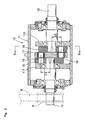
- the non-synchronous transmitting apparatus 10 has a box 11 for housing a non-synchronous transmitting mechanism shown in FIG. 4, an input shaft 12 and an output shaft 13.
- the input shaft 12 is inserted through the box 11 from one direction to a rotating axis direction
- the output shaft 13 is inserted through the box 11 from another direction to the rotating axis direction.
- One end of the input shaft 12, a pulley 9 is secured outside the box 11 and the other end of the input shaft 12 portion toward into the box 11 is sustained by a support wall 111 standing from an internal bottom wall of the box 11, a first rotating lever 15 is rotatably attached to the other end of the input shaft 12.
- the first rotating lever 15 is formed as substantially a sector shape.
- One end of the output shaft 13 is connected to the coupling device 20 (see FIG. 2) outside the box 11 and the other end of output shaft 12 portion toward into the box 11 is sustained by a support wall 112 standing from an internal bottom wall of the box 11, a second rotating lever 16 is rotatably attached to the other end of the output shaft 13.
- the first rotating lever 16 is formed as substantially a sector shape.
- the second rotating lever 16 is attached so as to face the first rotating lever 15 attached to the input shaft 12.
- a connecting lever 17 is interposed between the first and second rotating levers 15 and 16.
- the connecting lever 17 is rotatably connected to the first rotating lever 15 via a first connecting pin 18 arranged at a position eccentric with the input shaft 12 as well as rotatably connected to the second rotating lever 16 via a second connecting pin 19 arranged at a position eccentric with the input shaft 13.
- a distance L1 between the rotating axis of the first rotating lever 15 (rotating axis of the input shaft 12) and that of the first connecting pin 18, and a distance L2 between the rotating axis of the first rotating lever 16 (rotating axis of the input shaft 13) and that of the second connecting pin 19, are set in the same.
- the input shaft 12 and the output shaft 13 are arranged at a position eccentric to the box 11.
- the input shaft 12 is supported to the box 11 mounted with the pulley 9 at its one end and the support wall 111 by a bearing; on the other hand, the output shaft 13 is supported to the main body case 11 and the support wall 112 by a bearing.
- the rotation of the driving section of the press machine 1 is transmitted sequentially to the input shaft 12, the first rotating lever 15, the first connecting pin 18, the connecting lever 17, the second connecting pin 19, the second rotating lever 16 and the output shaft 13.
- the input shaft 12 and the output shaft 13 are at an eccentric position to the other, and the connecting lever 17 is connected to the first and second rotating levers 15 and 16 at the rotational axis and the eccentric position.
- a revolution of the input shaft 12 at a constant rotating speed is transmitted to the output shaft 13 the revolution at a variable rotational speed, enable connecting lever 17 rotate a faster and a slower rotational speeds to the constant rotational speed of the input shaft 12.
- the input shaft 12 is driven at the constant rotational speed and a circular locus P of the rotational axis of the first connecting pin 18 is shown with positions (P1, P2, P3 and to P12) with an equal interval of an angle of 30°.
- the locus P is shown as one end of the distance L1 (a line between the rotational axis of the first rotating lever 15 and the rotational axis of the first connecting pin 18).
- the output shaft 13 is positioned eccentric to the input shaft 12, a locus R of the rotational axis of the second connecting pin 19 is shown with position (R1, R2, R3 and to R12) with a variable interval of an angle of corresponding to the positions of the rotational axis of the first connecting pin 18 there of.
- the locus R is shown as one end of the distance L2 (a line between the rotational axis of the second rotating lever 16 and the rotational axis of the second connecting pin 19). Therefore, while the locus P rotates in the constant rotational speed means of with the equal interval, the locus R rotates in the variable rotational speed means of with the variable interval.
- the output shaft 13 is in the rotational state period of time of T1, wherein the rotational speed is faster than the input shaft 12 thereof, in the case where the input shaft 12 is rotated within a range of the crank angle of Feeding-Phase period of time (270° to 90°), the Feeding-Phase period of time completes (crank angle of 90°) of the output shaft 13 comes faster than the Feeding-Phase period of time completes (crank angle of 90°) of the input shaft 12 (T1 in FIG. 6).
- the output shaft 13 becomes in a rotation-stopped state (non-rotating period of time T in FIG. 6) until the input shaft 12 reaches to the crank angle of 90°.
- the output shaft 13 rotates by an angle of 180° while the input shaft 12 is rotated by an angle of 160°, the output shaft 13 is in the non rotational state during the input shaft 12 is rotating between the Crank Angle of 70° and 90°.
- the output shaft 13 of the non-synchronous transmitting apparatus 10 is connected to a cam shaft 32 projected from a box 31 of the angle indexing apparatus 7 by a coupling device 20.
- the rotation of the output shaft 13 of the non-synchronous transmitting apparatus 10 is transmitted to a driving shaft 33 of the angle indexing apparatus 7.
- the angle indexing apparatus 7 employs known angle indexing mechanism, whereas includes a cam unit having a cam driven by a cam shaft 32, and an indexing unit having an output shaft and a plurality of cam rollers contacted to the cam unit.
- the driving shaft 33 is arranged so as to upwardly project from an upper wall of the box 31, and is connected to a rotatably driving section (not shown) of the stacking cavity device 51 of the press die 5 via a tension unit 35.
- the tension unit 35 is provided with a pair of tension pulley 39; 39, which connects a pulley 36 mounted to the driving shaft 33 and a pulley 37 mounted to the press die by a belt 38 and applies a tension to the belt 38.
- the feeder 3 feeds the thin-strip material W into the press die 5.
- the thin-strip material W is fed to each cavity so that each process can be carried out.
- an upper press die is positioned near the Upper Dead Point within a range of the Crank Angle from 270°, to 90°(the Feed-Phase period of time) and the feeder 3 feed the thin-strip material W, and in a range from 90° to 270° (the Machining-Phase period of time), the upper press die moves down toward a lower press die, and thereafter, each pilot protrusions jump into the pilot guide holes as to carry out process.
- the connecting lever 17 is connected to the first rotating lever 15 via the first connecting pin 18; on the other hand, the second connecting pin 19 is connected to the second rotating lever 16 rotating together with the output shaft 13 positioned eccentrically with the input shaft 12.
- the constant rotational speed of the input shaft 12 is transmitted and transferred to the variable rotational speed of the output shaft 13.
- the variable rotation of the output shaft 13 is transmitted to the cam shaft 32 of the angle indexing apparatus 7 by the coupling devise 20 so as to make an intermittent rotation of the driving shaft 33 of the angle indexing apparatus 7.
- an accelerated speed is transmitted to the sequentially rotating stacking cavity device 51 of the press die 5.
- the stacking cavity driving device 51 is rotating in a high speed, the stacking cavity device is in the pivoting motion state immediately after the rotating state completion due to an inertia force.
- pilot protrusion arranged in the upper portion of the press die jump into the pilot guide holes, as well as punching out from the thin-strip material and in the stacking cavity device 51, stacking member or stacking core is formed.
- the angle indexing apparatus 7 rotates the stacking cavity device in the predetermined angle, and thereafter, the non-rotating period of time T is set until the Feeding-Phase period of time is completed.
- the pivoting motion state by the inertia force of the rotation of the stacking cavity device is settled during the non-rotating period of time T, and the predetermined position of the pilot guide holes is secured correctly where the pilot protrusions arranged in the upper portion of the press die jump into. Therefore, it is possible to achieve a high-speed operation.
- the driving shaft 33 of the angle indexing apparatus 7 is rotated at the variable rotational speed, and non-rotating period of time top period T is set; therefore, it is possible to maintain high speed operation without reducing the strength of the angle indexing apparatus 7 or without reducing indexing angle of the angle indexing apparatus.
- a non-synchronous transmitting apparatus in order to secure the non-rotating state period on the put shaft of the angle indexing apparatus, a non-synchronous transmitting apparatus is installed, when the constant rotational speed is transmitted to the input of the non-synchronous transmitting apparatus 10 from the driving unit of the press machine 1.
- a non-synchronous transmitting apparatus 10 transform and transmit the output shaft 13 of the non-synchronous apparatus a variable rotational speed.
- the input shaft 12 of the angle indexing apparatus 7 rotates at variable speed and thus, stacking cavity device rotates in an accelerated manner and its rotating period time is shorter than the Feeding-Phase period of time of the press machine 1.
- the angle indexing apparatus 7 has the non-rotation period of time T until the Feeding-Phase period is completed after the rotation of the angle indexing apparatus 7 completes.
- each pilot protrusions punch arranged at an upper portion of the press die jump into pilot protrusion guide holes respectably to predetermined guide holes arranged in the stacking cavity device, with no interference and no collision. Therefore, it is possible to achieve a high-speed operation.
- the angle indexing apparatus 7 connected to the output shaft 12 of the non-synchronous transmitting apparatus 10 has an advanced rotating state with respect to the Feeding-Phase period of the press machine 1.
- the non-rotating state period of time is set prior to the Machining-Phase period of the press machine 1 starts, and thereby, pivoting motion of the stacking cavity device is settled prior to the Machining-phase period of time starts. Therefore, the non-rotating period of time T is provided without making small the index angle of the angle indexing apparatus 7, the angle indexing apparatus 7 can be configured without reducing the strength of the angle indexing apparatus itself.
- the driving shaft may be stopped at a predetermined position using a servo motor in place of the angle indexing apparatus 7.
- a publicly known non-synchronous transmitting apparatus may be employed.
Landscapes
- Engineering & Computer Science (AREA)
- Power Engineering (AREA)
- Manufacturing & Machinery (AREA)
- Press Drives And Press Lines (AREA)
- Manufacture Of Motors, Generators (AREA)
- Transmission Devices (AREA)
- Manufacturing Cores, Coils, And Magnets (AREA)
Abstract
Description
in the stacking process, an angle indexing apparatus for rotating the stacking cavity device is arranged, and an output driving shaft of the angle indexing apparatus is provided with a non-rotating state period of time after a rotating state period of time completion and before a Feeding-Phase period of time completion, within the predetermined Feeding-Phase period of time range.
the angle indexing apparatus is connected to the driving unit of the press machine via a non-synchronous transmitting apparatus, and an output shaft of the non-synchronous transmitting apparatus has a variable rotating speed period of time with respect to an input shaft of the non-synchronous transmitting apparatus, and thereby, a non-rotating state period of time is provided after a rotating state period,of time completion and before a Feeding-Phase period of time completion, within the predetermined Feeding-Phase period of time range.
Claims (4)
- A stacked core assembly method, which performs stacking in a manner of sequentially rotating a stacking cavity device when assembling a stacked member, characterized in that,
in the stacking process, an angle indexing apparatus for rotating the stacking cavity device is arranged, and an output driving shaft of the angle indexing apparatus is provided with a non-rotating state period of time after a rotating state period of time completion and before a Feeding-Phase period of time completion, within the predetermined Feeding-Phase period of time range. - The stacked core assembly method according to claim 1, wherein the non-rotational state period of time is set by driving the output driving shaft of the angle indexing apparatus in an accelerated rotational speed during a predetermined Feed-Phase period of time.
- A stacked core assembly apparatus, which comprises a press machine, a feeder for feeding a thin-strip material into the press machine, and an indexing apparatus outputting an intermittent rotation when driven from the press machine is transmitted thereto, and a stacking member or stacked core is formed in an intermittent rotational stacking cavity device, whereas driven by the angle indexing apparatus intermittently and the angle indexing device is driven by a constant rotational speed of a driving unit of the press machine, characterized in that,
the angle indexing apparatus is connected to the driving unit of the press machine via a non-synchronous transmitting mechanism, and an output shaft of the non-synchronous transmitting mechanism has a variable rotating speed period of time with respect to an input shaft of the non-synchronous transmitting mechanism, and thereby, a non-rotating state period of time is provided after a rotating state period of time completion and before a Feeding-Phase period of time completion, within the predetermined Feeding-Phase period of time range. - The stacked core assembly apparatus according to claim 3, wherein the input and output shafts of the non-synchronous transmitting mechanism are arranged in an eccentric position, and are connected by a connecting levers, which is rotatably supported by pins eccentrically positioned with respect to each of rotational axis of the input shaft and that of the output shaft.
Applications Claiming Priority (3)
| Application Number | Priority Date | Filing Date | Title |
|---|---|---|---|
| JP2001178657A JP3850232B2 (en) | 2001-06-13 | 2001-06-13 | Laminated core processing method and apparatus |
| JP2001178657 | 2001-06-13 | ||
| PCT/JP2002/005740 WO2002103726A1 (en) | 2001-06-13 | 2002-06-10 | Method and device for machining stacked core |
Publications (3)
| Publication Number | Publication Date |
|---|---|
| EP1396868A1 true EP1396868A1 (en) | 2004-03-10 |
| EP1396868A4 EP1396868A4 (en) | 2005-11-23 |
| EP1396868B1 EP1396868B1 (en) | 2007-03-07 |
Family
ID=19019323
Family Applications (1)
| Application Number | Title | Priority Date | Filing Date |
|---|---|---|---|
| EP02733443A Expired - Lifetime EP1396868B1 (en) | 2001-06-13 | 2002-06-10 | Method and device for machining stacked core |
Country Status (7)
| Country | Link |
|---|---|
| US (2) | US7020948B2 (en) |
| EP (1) | EP1396868B1 (en) |
| JP (1) | JP3850232B2 (en) |
| KR (1) | KR100874711B1 (en) |
| CN (1) | CN1249741C (en) |
| DE (1) | DE60218663T2 (en) |
| WO (1) | WO2002103726A1 (en) |
Families Citing this family (7)
| Publication number | Priority date | Publication date | Assignee | Title |
|---|---|---|---|---|
| JP3850232B2 (en) * | 2001-06-13 | 2006-11-29 | 株式会社山田ドビー | Laminated core processing method and apparatus |
| JP4659441B2 (en) * | 2004-11-29 | 2011-03-30 | 黒田精工株式会社 | Laminated iron core and method for manufacturing the same |
| JP4498154B2 (en) * | 2005-01-27 | 2010-07-07 | ファナック株式会社 | Motor manufacturing method and motor manufacturing apparatus |
| KR101005859B1 (en) * | 2008-07-10 | 2011-01-05 | 나라엠앤디(주) | Step Lamination Press Molding Equipment |
| CN102052390B (en) * | 2009-10-30 | 2013-08-21 | 鸿富锦精密工业(深圳)有限公司 | Articulated mechanism |
| CN107565766B (en) * | 2016-06-30 | 2019-04-09 | 上海金陵电机股份有限公司 | A kind of stator outer press mounting accurately guides floating and presses press-in device |
| IT201700059495A1 (en) * | 2017-05-31 | 2018-12-01 | L A E Lughese Attrezzature Per L Elettromeccanica S R L | PROCESS, TAPE FEEDING SYSTEM AND PLANT FOR THE PRODUCTION OF LAMELLAR NUCLEI FOR TRANSFORMERS |
Family Cites Families (14)
| Publication number | Priority date | Publication date | Assignee | Title |
|---|---|---|---|---|
| US5123155A (en) * | 1983-03-25 | 1992-06-23 | L. H. Carbide Corporation | Apparatus and method for manufacturing laminated parts |
| US5960533A (en) * | 1983-03-25 | 1999-10-05 | L. H. Carbide Corporation | Apparatus for manufacture of laminated parts |
| JPS6099437A (en) * | 1983-11-04 | 1985-06-03 | Matsushita Electric Ind Co Ltd | mold equipment |
| JPS61135995A (en) * | 1984-12-05 | 1986-06-23 | Hitachi Ltd | Fixed scroll positioning assembly method and positioning assembly device |
| JPH07112576B2 (en) * | 1986-01-29 | 1995-12-06 | 黒田精工株式会社 | Rotating device for die unit for laminated core |
| JPH03174927A (en) * | 1990-04-26 | 1991-07-30 | Asmo Co Ltd | Manufacturing device for laminated iron core |
| US5163217A (en) * | 1991-04-24 | 1992-11-17 | Kuroda Precision Industries Ltd. | Die for manufacturing laminated core |
| US5551142A (en) * | 1995-01-05 | 1996-09-03 | Dayton-Phoenix Group, Inc. | Stator lamination jig system |
| JPH08256453A (en) | 1995-03-17 | 1996-10-01 | Mitsubishi Electric Corp | Iron core mounting tool and iron core punching device for iron core grooving |
| US5799387A (en) * | 1996-06-05 | 1998-09-01 | L.H. Carbide Corpordation | Lamina stack having a plurality of outer perimeter configurations and an apparatus and method for manufacturing said stack |
| US5881450A (en) * | 1996-12-05 | 1999-03-16 | L.H. Carbide Corporation | Dual action indexing system and method for a die assembly |
| JP2000094055A (en) | 1998-09-18 | 2000-04-04 | Sawafuji Electric Co Ltd | Laminated core manufacturing equipment |
| JP3850232B2 (en) * | 2001-06-13 | 2006-11-29 | 株式会社山田ドビー | Laminated core processing method and apparatus |
| JP2003094120A (en) * | 2001-09-25 | 2003-04-02 | Yamada Dobby Co Ltd | Laminate core processing equipment |
-
2001
- 2001-06-13 JP JP2001178657A patent/JP3850232B2/en not_active Expired - Lifetime
-
2002
- 2002-06-10 WO PCT/JP2002/005740 patent/WO2002103726A1/en not_active Ceased
- 2002-06-10 DE DE60218663T patent/DE60218663T2/en not_active Expired - Lifetime
- 2002-06-10 EP EP02733443A patent/EP1396868B1/en not_active Expired - Lifetime
- 2002-06-10 KR KR1020037002055A patent/KR100874711B1/en not_active Expired - Lifetime
- 2002-06-11 CN CNB028020510A patent/CN1249741C/en not_active Expired - Lifetime
- 2002-06-11 US US10/344,527 patent/US7020948B2/en not_active Expired - Lifetime
-
2005
- 2005-10-31 US US11/261,507 patent/US7168158B2/en not_active Expired - Lifetime
Also Published As
| Publication number | Publication date |
|---|---|
| US7168158B2 (en) | 2007-01-30 |
| DE60218663D1 (en) | 2007-04-19 |
| US20030172519A1 (en) | 2003-09-18 |
| KR20030025288A (en) | 2003-03-28 |
| CN1463449A (en) | 2003-12-24 |
| KR100874711B1 (en) | 2008-12-18 |
| DE60218663T2 (en) | 2007-11-08 |
| JP3850232B2 (en) | 2006-11-29 |
| EP1396868A4 (en) | 2005-11-23 |
| US20060048377A1 (en) | 2006-03-09 |
| EP1396868B1 (en) | 2007-03-07 |
| JP2002361336A (en) | 2002-12-17 |
| WO2002103726A1 (en) | 2002-12-27 |
| CN1249741C (en) | 2006-04-05 |
| WO2002103726A8 (en) | 2003-03-27 |
| US7020948B2 (en) | 2006-04-04 |
Similar Documents
| Publication | Publication Date | Title |
|---|---|---|
| US4615207A (en) | Progressive metal mold apparatus for production of laminated iron cores | |
| US6814217B2 (en) | Method and apparatus utilizing servo motors for placing parts onto a moving web | |
| JP3177536B2 (en) | Machine and method for cutting a roll or log of web material into a plurality of small rolls | |
| EP1396868B1 (en) | Method and device for machining stacked core | |
| US6412166B1 (en) | Mounting apparatus for electronic component | |
| JP2611720B2 (en) | Continuous wavy body cutting device | |
| US5881450A (en) | Dual action indexing system and method for a die assembly | |
| US20030062133A1 (en) | Laminated core machining apparatus | |
| JP7659900B2 (en) | Clamping and Hemming Devices | |
| EP0955156A1 (en) | Device for slitting and creasing a sheet cardboard material | |
| JP4581296B2 (en) | Press unit with rotation function | |
| JP2000117561A (en) | Work assembling device and work assembling method | |
| JP7397250B2 (en) | Wire cutting device | |
| JPH02239580A (en) | Constriction forming machine and forming device with constriction forming machine | |
| US5611235A (en) | Power distribution mechanism in a stamping and forming machine and method | |
| US4620468A (en) | Punching machine | |
| JPH1113773A (en) | Synchronous drive transmission shaft and press die | |
| JPH0760376A (en) | Method and apparatus for punching iron core punching plate for rotating electric machine | |
| PL175678B1 (en) | Rotary-valve-controlled device for removing cans from a ram of body making apparatus | |
| SU1304964A1 (en) | Horizontal mechanical automatic press | |
| KR100356628B1 (en) | Press apparatus for pressing mold | |
| SU1303237A1 (en) | Arrangement for stamping articles from continuous material | |
| JP2003039266A (en) | Multi-axis head | |
| JP3056825B2 (en) | Paper bundle processing device control method | |
| JPH0890494A (en) | Rotary punch unit |
Legal Events
| Date | Code | Title | Description |
|---|---|---|---|
| PUAI | Public reference made under article 153(3) epc to a published international application that has entered the european phase |
Free format text: ORIGINAL CODE: 0009012 |
|
| 17P | Request for examination filed |
Effective date: 20030228 |
|
| AK | Designated contracting states |
Kind code of ref document: A1 Designated state(s): AT BE CH CY DE DK ES FI FR GB GR IE IT LI LU MC NL PT SE TR |
|
| AX | Request for extension of the european patent |
Extension state: AL LT LV MK RO SI |
|
| A4 | Supplementary search report drawn up and despatched |
Effective date: 20051007 |
|
| RIC1 | Information provided on ipc code assigned before grant |
Ipc: 7B 21D 43/22 B Ipc: 7H 02K 15/02 B Ipc: 7B 21D 28/22 B Ipc: 7H 01F 41/02 A |
|
| GRAP | Despatch of communication of intention to grant a patent |
Free format text: ORIGINAL CODE: EPIDOSNIGR1 |
|
| GRAS | Grant fee paid |
Free format text: ORIGINAL CODE: EPIDOSNIGR3 |
|
| GRAA | (expected) grant |
Free format text: ORIGINAL CODE: 0009210 |
|
| AK | Designated contracting states |
Kind code of ref document: B1 Designated state(s): DE IT |
|
| RBV | Designated contracting states (corrected) |
Designated state(s): DE IT |
|
| REF | Corresponds to: |
Ref document number: 60218663 Country of ref document: DE Date of ref document: 20070419 Kind code of ref document: P |
|
| PLBE | No opposition filed within time limit |
Free format text: ORIGINAL CODE: 0009261 |
|
| STAA | Information on the status of an ep patent application or granted ep patent |
Free format text: STATUS: NO OPPOSITION FILED WITHIN TIME LIMIT |
|
| 26N | No opposition filed |
Effective date: 20071210 |
|
| REG | Reference to a national code |
Ref country code: DE Ref legal event code: R082 Ref document number: 60218663 Country of ref document: DE Representative=s name: KRAMER BARSKE SCHMIDTCHEN PATENTANWAELTE PARTG, DE Ref country code: DE Ref legal event code: R081 Ref document number: 60218663 Country of ref document: DE Owner name: MINEBEA MITSUMI INC., JP Free format text: FORMER OWNERS: YAMADA DOBBY CO. LTD., BISAI, AICHI, JP; MINEBEA CO., LTD., NAGANO, JP Ref country code: DE Ref legal event code: R081 Ref document number: 60218663 Country of ref document: DE Owner name: YAMADA DOBBY CO. LTD., BISAI, JP Free format text: FORMER OWNERS: YAMADA DOBBY CO. LTD., BISAI, AICHI, JP; MINEBEA CO., LTD., NAGANO, JP |
|
| PGFP | Annual fee paid to national office [announced via postgrant information from national office to epo] |
Ref country code: IT Payment date: 20210511 Year of fee payment: 20 Ref country code: DE Payment date: 20210511 Year of fee payment: 20 |
|
| REG | Reference to a national code |
Ref country code: DE Ref legal event code: R071 Ref document number: 60218663 Country of ref document: DE |