EP1396816A2 - Method for sharpening a digital image - Google Patents
Method for sharpening a digital image Download PDFInfo
- Publication number
- EP1396816A2 EP1396816A2 EP03077656A EP03077656A EP1396816A2 EP 1396816 A2 EP1396816 A2 EP 1396816A2 EP 03077656 A EP03077656 A EP 03077656A EP 03077656 A EP03077656 A EP 03077656A EP 1396816 A2 EP1396816 A2 EP 1396816A2
- Authority
- EP
- European Patent Office
- Prior art keywords
- image
- digital image
- rendered
- lut
- gain
- Prior art date
- Legal status (The legal status is an assumption and is not a legal conclusion. Google has not performed a legal analysis and makes no representation as to the accuracy of the status listed.)
- Granted
Links
Images



Classifications
-
- G—PHYSICS
- G06—COMPUTING OR CALCULATING; COUNTING
- G06T—IMAGE DATA PROCESSING OR GENERATION, IN GENERAL
- G06T5/00—Image enhancement or restoration
- G06T5/73—Deblurring; Sharpening
- G06T5/75—Unsharp masking
-
- G—PHYSICS
- G06—COMPUTING OR CALCULATING; COUNTING
- G06V—IMAGE OR VIDEO RECOGNITION OR UNDERSTANDING
- G06V10/00—Arrangements for image or video recognition or understanding
- G06V10/20—Image preprocessing
- G06V10/30—Noise filtering
Definitions
- the invention relates generally to the field of digital image processing and, more particularly, to a method of image sharpening.
- sharpening is performed by a convolution process (for example, see A. K. Jain, Fundamentals of Digital Image Processing, Prentice-Hall: 1989, pp. 249-251).
- the process of unsharp masking is an example of a convolution-based sharpening process.
- an unsharp image is generated by convolution of the image with a lowpass filter (i.e., the unsharp image is given by i(x,y)**b(x,y)).
- the highpass, or fringe data is generated by subtracting the unsharp image from the original image (i.e., the highpass data is found with i(x,y)-i(x,y)**b(x,y)).
- This highpass data is then modified by either a gain factor ⁇ or a fringe function f() or both.
- the modified highpass data is summed with either the original image or the unsharp image to produce a sharpened image.
- a similar sharpening effect can be achieved by modification of the image in the frequency domain (for example, the FFT domain) as is well known in the art of digital signal processing.
- Noise amplification can be a special problem when sharpening a digital image originating from film. Specifically, image regions originally receiving little or no light exposure (also called D min ) on the film can appear quite noisy when the image is sharpened.
- Curlander in "Image Enhancement Using Digital Adaptive Filtering," Master's Thesis, Massachusetts Institute of Technology, 1977, p. 30-34, 48-49, 63,72-73, 93-94) describes methods of sharpening a digital image, where the highpass gain factor is determined from the lowpass signal value, the local contrast, or the highpass signal value. Curlander did not describe sharpening of a rendered image in such a way as to minimize the amplification of image D min noise.
- D min is also sometimes referred to as mask or base density.
- Underexposed film images typically have image areas containing D min . It is common to use the value of D min in the processing of digital images for the purpose of improving image quality.
- Terashita describes a method of using a mask density to improve the exposure estimate for an image. To this end, the mask density is subtracted from the average density. This increases the robustness of the determined color balance by decreasing the variability between different color negative films.
- Terashita's method does not ensure that regions of an image sensing device receiving little or no light exposure are specially handled to reduce the sharpening of noise.
- One embodiment requires that the sum of the two parameters equal one for all image signal levels.
- the method is mathematically equivalent to the unsharp mask equation.
- Shimazaki teaches that the two parameters are signal dependent with the signals representing image highlights resulting in the highest degree of sharpening.
- the two parameters are chosen such that the sharpening decreases as either the image signal or the unsharp signal decreases until the sharpening level is zero. At that point, the sharpening converts to blurring as the image signal or unsharp signal continue to decrease into the shadow region of the density range. Shimazaki's apparatus suffers from not accounting explicitly for the D min density level.
- the need is met according to the present invention by providing a method of sharpening a digital image having image pixels values that includes the steps of determining a D min value, representing a value corresponding to a minimum possible exposure for a system that produced the digital image; for each pixel value in the digital image providing a gain factor that is dependent on the difference between the pixel value and the D min value, such that pixel values nearer the D min value have smaller gain factors; and using the gain factors to sharpen the digital image.
- the present invention has the advantage of producing sharper images without amplifying noise associated with the portion of film receiving little or no light exposure (also called D min ).
- the computer program may be stored in a computer readable storage medium, which may comprise, for example; magnetic storage media such as a magnetic disk (such as a hard drive or a floppy disk) or magnetic tape; optical storage media such as an optical disc, optical tape, or machine readable bar code; solid state electronic storage devices such as random access memory (RAM), or read only memory (ROM); or any other physical device or medium employed to store a computer program.
- a computer readable storage medium may comprise, for example; magnetic storage media such as a magnetic disk (such as a hard drive or a floppy disk) or magnetic tape; optical storage media such as an optical disc, optical tape, or machine readable bar code; solid state electronic storage devices such as random access memory (RAM), or read only memory (ROM); or any other physical device or medium employed to store a computer program.
- a digital image typically includes one or more two-dimensional arrays of numbers.
- a color digital image may include three arrays representing red, green, and blue pixel values respectively, or a monochrome image may include one array of pixel values corresponding to light intensities.
- the value of a pixel of a digital image located at coordinates ( x , y ), referring to the x th row and the y th column of a digital image shall herein comprise a triad of values [r(x,y), g(x,y), b(x,y)] respectively referring to the values of the red, green and blue digital image channels at location (x,y).
- a digital image may be considered as comprising a certain number of digital image channels.
- the image comprises three channels, namely, red, green and blue spectral channels.
- the present invention describes a method of sharpening an image where the sharpening amount (applied to any local region of the image) is dependent on the noise characteristics of the source image signal.
- the present invention is useful for digital images from a film source.
- the present invention ensures that image regions near D min in the source image have reduced sharpening, thereby reducing noise visibility.
- LUT generator 4 for creating a LUT (Look-Up-Table) ⁇ LUT [] that defines the relationship between the sharpening gain factor ⁇ and the intensity of the digital image.
- LUT generator 4 could be a mathematical function just as easily as a LUT. The method of creating the LUT will be described hereinbelow.
- Xmax, Ymin and Ymax are arrived at empirically by processing, printing and viewing prints to determine optimal values for these parameters.
- X min 279
- X max 579
- Y min 1.0
- Y max 3.0.
- ⁇ LUT [] the function represented by ⁇ LUT [] is a monotonic function of pixel value that increases from the D min value (X min ) to a predetermined pixel value (X max ) and is constant for pixel values that exceed the predetermined pixel value.
- an original image 2 i(x,y) having x o rows and y o columns is input to the image sharpener 6 for sharpening the image according to the gain LUT ⁇ LUT [] produced by the LUT generator 4 .
- the original image may be a digitized version of a photographic film image, or a digital image captured by an electronic camera.
- the sharpener 6 receives the original image 2 and outputs a sharpened image 22 .
- the lowpass filter is a Gaussian lowpass filter.
- This Gaussian filter is a two-dimensional, circularly symmetric, low-pass filter whose filter coefficients may be derived by the following formula which is well known in the art: where:
- the filter coefficients are as follows:
- the gain factor ⁇ (x,y) for each pixel value in the digital image is dependent on the difference between the pixel value and the D min value, such that pixel values nearer the D min value have smaller gain factors.
- the gain factors are used to sharpen the digital image as follows.
- An unsharp image is generated by convolution of the image with a lowpass filter (i.e., the unsharp image is given by i(x,y)**b(x,y)).
- the highpass, or fringe data is generated by subtracting the unsharp image from the original image (i.e., the highpass data is found with i(x,y) - i(x,y)**b(x,y)).
- This highpass data is then modified by the signal dependent gain factor ⁇ (x,y) and possibly a fringe function f().
- the fringe function is identity and can be omitted without effect.
- the gain factor ⁇ (x,y) is dependent on the value of the unsharp original image.
- the gain factor is dependent on the unsharp image
- the gain factor ⁇ (x,y) could have been dependent on the original image or an unsharp image made with a different lowpass filter with similar effect.
- the modified highpass data is summed with the unsharp image to produce a sharpened image. (Those skilled in the art will recognize that this is equivalent with summing the modified highpass data to the original image, with an appropriate modification to the gain factors.)
- Each channel of the digital image may be operated upon by the sharpener 6 .
- the parameters X min , and X max , used by the LUT generator 4 be adjusted accordingly, as typical consumer films generally have different D min values in each of the color channels (blue channel D min is typically higher than green channel D min which is typically higher than red channel D min ).
- each color channel is treated in an independent manner.
- the gain factor may sometimes be desirable for the gain factor to be fixed across color channels at each pixel location (x,y) throughout the image. This can be accomplished by taking the mean, median, minimum or some other combination of the determined gain factors at each pixel location.
- a luminance channel is created as is commonly known in the art by making a linear combination of the image's color channels. Then, this single channel is input to the sharpener 6 for creating a sharpened output image.
- the luminance channel l(x,y) is created by linearly combining all the color channels of the image. For example: where:
- the preferred values for the red, green, and blue coefficient weighting factors are all equally 1 /3.
- the input image is a color image consisting of red, green, and blue color channels
- a matrix is first applied to the image in order to produce a luminance channel and two or more color difference channels.
- the unsharp mask process is applied to the luminance channel via the sharpener 6.
- an inverse matrix is applied to the luminance and color difference channels to generate an enhanced color image having red green and blue channels.
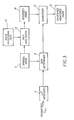
- FIG. 3 A second embodiment of the present invention is shown in Fig. 3.
- the original image 2 i(x,y) is input to a path applicator 14, along with an image processing path 10 .
- the path applicator 14 modifies the original image 2 i(x,y) using the image processing path 10 , in order to create a rendered image 16 R(x,y).
- the original image 2 a digitization of film, is not suitable for an output device such as a CRT monitor or a printer.
- the image processing path applicator 14 applies an image processing path 10 (a series of image transforms) for the purpose of creating a rendered image 16 R(x,y).
- an image processing path 10 includes one or more image transforms 20 1-M .
- An image transform 20 is an operation that accepts an input image and possibly control parameters, and in a repeatable fashion, generates an output image.
- an example image processing path 10 is shown.
- This exemplary image processing path 10 composed of image transforms 20 m designed to create a rendered image that is a photographic print from an input image that is a digital scan of a photographic negative. Examples of such image processing paths 10 are disclosed in US 6,097,470 and 6,097,471 , both issued August 1, 2000, to Buhr et al.
- the image processing path 10 includes an imaging device response linearizer 42 that applies compensation for non-linearities in the response of the imaging device.
- the image processing 10 path also includes a balance applicator 44 that applies a scene balance algorithm to the image.
- Image balancing is often performed by a scene balance algorithm (SBA) or automatic exposure determination algorithm (such as are used in high speed optical printers or in a Photo-CD scanner, see for example US 4,945,406 issued July 31, 1990 to Cok).
- SBA scene balance algorithm
- the image processing path includes a contrast adjuster 46 that determines and applies tonal modifications to the image. The contrast of the image may be estimated by an automatic algorithm.
- the contrast of the digital image may likewise be modified to a preferred level of contrast.
- An example of an algorithm that estimates image contrast and provides a means of adjusting the contrast of the image is described in US 5,822,453 issued October 13, 1998 to Lee et al.
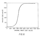
- the image processing path 10 also includes a renderer 48 such as described in US 6,097,470 issued August 1, 2000 to Buhr et al. Rendering either a digital or optical image can with good accuracy be represented by a LUT (either one, three, or multi- dimensional.) For example, Fig.
- FIG. 6 shows the graph of a LUT that relates image pixel values to code values of an 8-bit printer, although those skilled in the art will recognize that many output image metrics may be used as the rendering space (for example, sRGB is common for viewing images on a computer monitor.)
- the LUT generator 4 is identical to the previous description of the LUT generator 4.
- the gain determiner 8 receives the original image 2 i(x,y) and the gain LUT output from the LUT generator 4 .
- the gain determiner 8 determines and outputs, for each pixel location (x,y) of the image, the appropriate gain factor ⁇ (x,y). This gain factor is found simply by performing a table look-up on the pixel values of the original image.
- ⁇ (x,y) ⁇ LUT [i(x,y)],
- the gain determiner 8 preferably performs a blurring operation (using either the lowpass filter b(x,y) or a different lowpass filter) on the original image before doing the table look-up.
- the sharpener 12 then receives the rendered image R(x,y) and the gain factors ⁇ (x,y) from the gain determiner 8, and outputs a sharpened rendered image 18.
- This embodiment enables the sharpening (of D min regions less than other regions to avoid unnecessary noise amplification) of a rendered image R(x,y) having pixel values whose relationship to the original film D min may not be straight forward by using the original image i(x,y) to determine appropriate gain factors ⁇ (x,y).
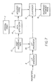
- Fig. 7 illustrates the third and preferred embodiment for applying sharpening to a rendered image in such a manner that the D min noise is not excessively amplified.
- the LUT generator 4 is as previously described.
- the gain LUT ⁇ LUT [] is then input, along with the image processing path 10, to the LUT propagator 24.
- the LUT propagator 24 propagates the gain LUT ⁇ LUT [] through the image transforms 20 1-M of the image processing path 10 and outputs a rendered gain LUT ⁇ R_LUT [] for producing rendered gain factors corresponding to the pixel code values of the rendered digital image 16 R(x,y).
- Rendered gain LUTs ⁇ R_LUT [], originating from a common gain LUT ⁇ LUT [], can appear quite different depending on the image transforms 20 1-M of the image processing path 10.
- a balance shift additive offset for each pixel value of the digital image
- a balance shift for a normally exposed original image is, for example, 0.
- Figs. 8a and 8b show the resulting rendered gain LUTs for the underexposed image and the normally exposed image.
- the rendered image created from the underexposed image will be sharpened less in the lower code values.
- the rendered image created from the normally exposed image can be sharpened more over a wider range of code values, since the D min region from the original image will be very dark (i.e. low code value) in the rendered image.
- Propagation of the gain LUT continues in a manner shown above, propagating the gain LUT through one transform at a time to create the rendered gain LUT ⁇ R_LUT [] from the original gain LUT, according to the image transforms of the image processing path. Note that it is possible to combine several image transforms into a single image transform before propagating. In addition, when the gain LUT has been propagated through the final image transform of the image processing chain, then the rendered gain LUT ⁇ R_LUT [] is equivalent to the last propagated gain LUT ⁇ P_LUT [].
- certain image transforms 20 have little or no impact on the propagated D min value, and thus may be skipped or omitted when calculating the propagated D min value. For instance, spatial operations such as red eye correction generally do not modify the value of D min and may be omitted. Other, more complicated image transforms 20, such as object recognition do not affect the propagated value of D min and may also be ignored. These ignored image transforms are not relevant to the propagated D min value.
- the LUT propagator 24 could also operate by propagating only certain control parameters through the image processing path, and then the rendered gain LUT could be constructed using a mathematical formula similar to Equation (1).
- X min and X max could be propagated through the image processing path simply by applying each image transform of the image processing path to the values of X min and X max as if they were the values of two pixels of an image undergoing modification by the image processing path. The result of this process would be a rendered version of X min and X max , X minR and X maxR , respectively.
- the LUT propagator 24 would then construct the rendered gain control LUT ⁇ R_LUT [] simply by evaluating Equation (1), substituting X minR for X min and substituting X maxR for X max .
- the original image 2 i(x,y) is input to a path applicator 14 , along with an image processing path 10 .
- the path applicator 14 modifies the original image 2 i(x,y) using the image processing path 14 , in order to create a rendered image 16 R(x,y), as was disclosed above.
- the sharpener 12 then inputs the rendered image 16 R(x,y) and the rendered gain LUT ⁇ R_LUT [] from the LUT propagator 24 and produces a sharpened rendered image 18.
- This embodiment enables the sharpening (of D min regions less than other regions to avoid unnecessary noise amplification) of a rendered image having pixel values whose relationship to the original film D min may not be straight forward.
- unsharp masking such as provided by Eq. (2)
- the unsharp mask process can be applied to each channel of the color image.
- the unsharp mask process is applied in the following manner, commonly known in the art.
- a matrix is first applied to the image in order to produce a luminance channel and two or more color difference channels.
- the unsharp mask process is applied to the luminance channel.
- an inverse matrix is applied to the luminance and color difference channels to generate an enhanced color image having red, green, and blue channels.
- the unsharp mask process may be applied to only a single image channel (e.g. the green channel), and the modified highpass data may be summed with each color channel in order to generate an enhanced color image.
- a single image channel e.g. the green channel
- the modified highpass data may be summed with each color channel in order to generate an enhanced color image.
- Eq. (2) and the present invention generally describe the sharpening applied to the image as being performed by an unsharp mask, that is not necessarily the case.
- the unsharp mask process can be reconfigured as a single filter than can be applied with convolution to the image and produce results identical to the unsharp mask.
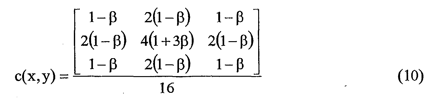
- the filter coefficients of b(x,y) are given as:
- Application of a filter c(x,y) with a convolution having coefficients given as will produce identical results compared with using filter b(x,y) in the unsharp mask of Equation (2).
- Such modifications to the preferred embodiment by the grouping of operations in the image sharpener 6 such as can be determined by methods well known in algebra and digital signal processing will be evident to those of skill in this art and are within the scope of the present invention.
Landscapes
- Engineering & Computer Science (AREA)
- Physics & Mathematics (AREA)
- General Physics & Mathematics (AREA)
- Theoretical Computer Science (AREA)
- Multimedia (AREA)
- Image Processing (AREA)
- Facsimile Image Signal Circuits (AREA)
- Picture Signal Circuits (AREA)
Abstract
Description
- f() = fringe function
- i(x,y)**b(x,y) = lowpass image (also called unsharp image)
- i(x,y)-i(x,y)**b(x,y) = highpass image
- ** denotes two dimensional convolution
- (x,y) denotes the xth row and the yth column of an image

For example:

- i(x,y) is the
original image 2. - f() = fringe function
- R(x,y)**b(x,y) = lowpass image (also called unsharp image)
- R(x,y)-R(x,y)**b(x,y) = highpass image
- ** denotes two dimensional convolution
- (x,y) denotes the xth row and the yth column of an image

Claims (10)
- A method of sharpening a digital image having image pixels values, comprising the steps of:a) determining a Dmin value, representing a value corresponding to a minimum possible exposure for a system that produced the digital image;b) for each pixel value in the digital image providing a gain factor that is dependent on the difference between the pixel value and the Dmin value, such that pixel values nearer the Dmin value have smaller gain factors; andc) using the gain factors to sharpen the digital image.
- The method of sharpening a digital image claimed in claim 1, further comprising the steps of:a) applying an image processing path including one or more image transforms to the digital image resulting in a rendered digital image;b) using the gain factors to sharpen the rendered digital image.
- The method of sharpening a digital image claimed in claim 1, further comprising the steps of:a) applying an image processing path including one or more image transforms to the original digital image resulting in a rendered digital image;b) applying the image processing path to the gain factors to form rendered gain factors; andc) using the rendered gain factors to sharpen the rendered digital image.
- The method claimed in claim 1, wherein the gain factors are provided by a lookup table that models a monotonic function of pixel value.
- The method claimed in claim 4, wherein the monotonic function is increasing from the Dmin value to a predetermined pixel value and constant for pixel values that exceed the predetermined pixel value.
- A computer program product for performing the method claimed in claim 1.
- The computer program product claimed in claim 6, wherein the method further comprises the steps of:a) applying an image processing path including one or more image transforms to the original digital image, resulting in a rendered digital image; andb) using the gain factors to sharpen the rendered digital image.
- The computer program product claimed in claim 6, wherein the method further comprises the steps of:a) applying an image processing path including one or more image transforms to the original digital image, resulting in a rendered digital image;b) applying the image processing path to the gain factors to form rendered gain factors; andc) using the rendered gain factors to sharpen the rendered digital image.
- The computer program product claimed in claim 6, wherein the gain factors are provided by a lookup table that models a monotonic function of pixel value
- The computer program product claimed in claim 9, wherein the monotonic function is increasing from the Dmin value to a predetermined pixel value and constant for pixel values that exceed the predetermined pixel value.
Applications Claiming Priority (2)
| Application Number | Priority Date | Filing Date | Title |
|---|---|---|---|
| US235130 | 1981-02-17 | ||
| US10/235,130 US7228004B2 (en) | 2002-09-05 | 2002-09-05 | Method for sharpening a digital image |
Publications (3)
| Publication Number | Publication Date |
|---|---|
| EP1396816A2 true EP1396816A2 (en) | 2004-03-10 |
| EP1396816A3 EP1396816A3 (en) | 2004-10-06 |
| EP1396816B1 EP1396816B1 (en) | 2007-08-15 |
Family
ID=31715298
Family Applications (1)
| Application Number | Title | Priority Date | Filing Date |
|---|---|---|---|
| EP03077656A Expired - Lifetime EP1396816B1 (en) | 2002-09-05 | 2003-08-25 | Method for sharpening a digital image |
Country Status (4)
| Country | Link |
|---|---|
| US (1) | US7228004B2 (en) |
| EP (1) | EP1396816B1 (en) |
| JP (1) | JP4262557B2 (en) |
| DE (1) | DE60315568T2 (en) |
Cited By (1)
| Publication number | Priority date | Publication date | Assignee | Title |
|---|---|---|---|---|
| EP2998925A1 (en) * | 2014-09-17 | 2016-03-23 | Canon Kabushiki Kaisha | Image processing method, and image-pickup apparatus, image processing apparatus, and image processing program using the method |
Families Citing this family (23)
| Publication number | Priority date | Publication date | Assignee | Title |
|---|---|---|---|---|
| US6877916B2 (en) * | 2003-03-17 | 2005-04-12 | Irena Khaikin | Method for generating non-repeating patterns for printing |
| US7515765B1 (en) | 2004-01-30 | 2009-04-07 | Apple Inc. | Image sharpness management |
| AU2005267848A1 (en) * | 2004-07-30 | 2006-02-09 | Pacific Title & Arts Studio, Inc. | Method for conversion and reproduction of film images through a digital process |
| US20060093234A1 (en) * | 2004-11-04 | 2006-05-04 | Silverstein D A | Reduction of blur in multi-channel images |
| US7961357B2 (en) * | 2004-12-08 | 2011-06-14 | Electronics And Telecommunications Research Institute | Block artifact phenomenon eliminating device and eliminating method thereof |
| US8872906B2 (en) | 2005-01-05 | 2014-10-28 | Avantis Medical Systems, Inc. | Endoscope assembly with a polarizing filter |
| US8310530B2 (en) | 2006-05-19 | 2012-11-13 | Avantis Medical Systems, Inc. | Device and method for reducing effects of video artifacts |
| US8182422B2 (en) | 2005-12-13 | 2012-05-22 | Avantis Medical Systems, Inc. | Endoscope having detachable imaging device and method of using |
| US8797392B2 (en) | 2005-01-05 | 2014-08-05 | Avantis Medical Sytems, Inc. | Endoscope assembly with a polarizing filter |
| US8289381B2 (en) | 2005-01-05 | 2012-10-16 | Avantis Medical Systems, Inc. | Endoscope with an imaging catheter assembly and method of configuring an endoscope |
| US7683950B2 (en) * | 2005-04-26 | 2010-03-23 | Eastman Kodak Company | Method and apparatus for correcting a channel dependent color aberration in a digital image |
| WO2007087421A2 (en) | 2006-01-23 | 2007-08-02 | Avantis Medical Systems, Inc. | Endoscope |
| US8287446B2 (en) | 2006-04-18 | 2012-10-16 | Avantis Medical Systems, Inc. | Vibratory device, endoscope having such a device, method for configuring an endoscope, and method of reducing looping of an endoscope |
| TWI314301B (en) * | 2006-06-30 | 2009-09-01 | Primax Electronics Ltd | Adaptive image sharpening method |
| US8064666B2 (en) | 2007-04-10 | 2011-11-22 | Avantis Medical Systems, Inc. | Method and device for examining or imaging an interior surface of a cavity |
| EP2124189A1 (en) * | 2008-05-19 | 2009-11-25 | Mitsubishi Electric Information Technology Centre Europe B.V. | Image processing to enhance image sharpness |
| EP2124190B1 (en) * | 2008-05-19 | 2011-08-31 | Mitsubishi Electric Information Technology Centre Europe B.V. | Image processing to enhance image sharpness |
| JP4453777B2 (en) * | 2008-07-15 | 2010-04-21 | 日本ビクター株式会社 | Image quality improving apparatus and method |
| CN102137221A (en) * | 2010-01-22 | 2011-07-27 | 富士通微电子(上海)有限公司 | Method and system for sharpening digital video image |
| SE536510C2 (en) * | 2012-02-21 | 2014-01-14 | Flir Systems Ab | Imaging method for detail enhancement and noise reduction |
| US9251569B2 (en) * | 2013-09-10 | 2016-02-02 | Adobe Systems Incorporated | Removing noise from an image via efficient patch distance computations |
| US10963995B2 (en) | 2018-02-12 | 2021-03-30 | Samsung Electronics Co., Ltd. | Image processing apparatus and image processing method thereof |
| US12020408B2 (en) | 2021-06-22 | 2024-06-25 | Ati Technologies Ulc | Sharpening of images in non-linear and linear formats |
Family Cites Families (71)
| Publication number | Priority date | Publication date | Assignee | Title |
|---|---|---|---|---|
| JPS5913011B2 (en) * | 1974-06-21 | 1984-03-27 | 富士写真フイルム株式会社 | Photographic printing exposure control method |
| US4101216A (en) * | 1974-12-13 | 1978-07-18 | Gretag Aktiengesellschaft | Method and apparatus for print exposure control |
| CH596573A5 (en) * | 1975-08-14 | 1978-03-15 | Gretag Ag | |
| EP0012713B1 (en) * | 1978-10-20 | 1983-04-27 | GRETAG Aktiengesellschaft | Method for setting the exposure in the production of photographic copies |
| US4315318A (en) * | 1978-12-26 | 1982-02-09 | Fuji Photo Film Co., Ltd. | Method and apparatus for processing a radiation image |
| US4317179A (en) * | 1978-12-26 | 1982-02-23 | Fuji Photo Film Co., Ltd. | Method and apparatus for processing a radiographic image |
| JPS55116339A (en) * | 1979-02-28 | 1980-09-06 | Fuji Photo Film Co Ltd | Method and device for processing gradation of radiation picture of chest |
| JPS55116338A (en) * | 1979-02-28 | 1980-09-06 | Fuji Photo Film Co Ltd | Method and device for processing gradation of xxray picture of breast |
| US4666306A (en) * | 1984-01-19 | 1987-05-19 | Fuji Photo Film Co., Ltd. | Method and apparatus for detecting photographic image information |
| US4571635A (en) * | 1984-02-17 | 1986-02-18 | Minnesota Mining And Manufacturing Company | Method of image enhancement by raster scanning |
| JPS6159446A (en) * | 1984-08-31 | 1986-03-26 | Fuji Photo Film Co Ltd | Photographic printing device |
| US4747052A (en) * | 1984-11-14 | 1988-05-24 | Philips Medical Systems, Inc. | Radiation image processing |
| US4650316A (en) * | 1985-03-13 | 1987-03-17 | Fuji Photo Film Co., Ltd. | Method for detecting image information |
| US4827526A (en) * | 1985-04-16 | 1989-05-02 | Fuji Photo Film Co., Ltd. | Image information detecting/processing method |
| JPS6342575A (en) * | 1986-08-08 | 1988-02-23 | Dainippon Screen Mfg Co Ltd | Method and device for gradation conversion |
| US4891829A (en) * | 1986-11-19 | 1990-01-02 | Exxon Research And Engineering Company | Method and apparatus for utilizing an electro-optic detector in a microtomography system |
| JPH0746201B2 (en) * | 1986-12-05 | 1995-05-17 | 富士写真フイルム株式会社 | Out-of-focus image detection device and photo printing device |
| US4761819A (en) * | 1987-02-27 | 1988-08-02 | Picker International, Inc. | Adaptive noise reduction filter for reconstructed images |
| US4977521A (en) * | 1988-07-25 | 1990-12-11 | Eastman Kodak Company | Film noise reduction by application of bayes theorem to positive/negative film |
| US4945406A (en) * | 1988-11-07 | 1990-07-31 | Eastman Kodak Company | Apparatus and accompanying methods for achieving automatic color balancing in a film to video transfer system |
| JPH02278383A (en) * | 1989-04-19 | 1990-11-14 | Fuji Photo Film Co Ltd | Picture processing device |
| US5038388A (en) | 1989-05-15 | 1991-08-06 | Polaroid Corporation | Method for adaptively sharpening electronic images |
| US5081485A (en) * | 1989-07-14 | 1992-01-14 | Fuji Photo Film Co., Ltd. | Method for determining exposure amount in image copying apparatus |
| JP3373508B2 (en) | 1989-12-26 | 2003-02-04 | イーストマン コダック カンパニー | How to extend the linear range of an image captured on film |
| US5200765A (en) * | 1990-03-26 | 1993-04-06 | Eastman Kodak Company | Apparatus and method for calibrating a grey level printhead |
| US5049916A (en) * | 1990-08-23 | 1991-09-17 | Eastman Kodak Company | Automatic optimization of photographic exposure parameters through determination and utilization of extra system speed |
| US5131573A (en) * | 1991-03-22 | 1992-07-21 | Allegheny Ludlum Corporation | Method and device for shrouding a stream of molten metal |
| US5081692A (en) * | 1991-04-04 | 1992-01-14 | Eastman Kodak Company | Unsharp masking using center weighted local variance for image sharpening and noise suppression |
| US5224177A (en) * | 1991-10-31 | 1993-06-29 | The University Of Chicago | High quality film image correction and duplication method and system |
| US5561494A (en) * | 1992-06-15 | 1996-10-01 | Fuji Photo Film Co., Ltd. | Method of and apparatus for determining exposure amount in copying apparatus |
| US5279927A (en) * | 1992-07-23 | 1994-01-18 | Eastman Kodak Company | Aqueous developer for lithographic printing plates with improved desensitizing capability |
| US5316892A (en) * | 1992-07-23 | 1994-05-31 | Eastman Kodak Company | Method for developing lithographic printing plates |
| US5311251A (en) * | 1992-10-30 | 1994-05-10 | Eastman Kodak Company | Automatic setup of photographic printer |
| EP0612183B1 (en) * | 1993-02-16 | 1998-10-28 | Fuji Photo Film Co., Ltd. | Method for correcting the gray balance of a colour image recorded on a negative film |
| EP0617548B1 (en) * | 1993-03-24 | 2001-09-05 | Fujifilm Electronic Imaging Limited | Image colour modification |
| US5380635A (en) * | 1994-02-28 | 1995-01-10 | Minnesota Mining And Manufacturing Company | Dihydroperimidine squarylium dyes as antihalation and acutance materials for photographic and photothermographic articles |
| US5717469A (en) * | 1994-06-30 | 1998-02-10 | Agfa-Gevaert N.V. | Video frame grabber comprising analog video signals analysis system |
| US5719661A (en) * | 1994-07-27 | 1998-02-17 | Fuji Photo Film Co., Ltd. | Image reproducing apparatus and method of determining reproduction conditions |
| US5553859A (en) * | 1995-03-22 | 1996-09-10 | Lazer-Tron Corporation | Arcade game for sensing and validating objects |
| US5886353A (en) * | 1995-04-21 | 1999-03-23 | Thermotrex Corporation | Imaging device |
| US6058201A (en) * | 1995-05-04 | 2000-05-02 | Web Printing Controls Co., Inc. | Dynamic reflective density measuring and control system for a web printing press |
| US5835137A (en) * | 1995-06-21 | 1998-11-10 | Eastman Kodak Company | Method and system for compensating for motion during imaging |
| JPH09204077A (en) * | 1995-07-14 | 1997-08-05 | Hitachi Koki Co Ltd | Image forming device |
| US5703671A (en) * | 1995-08-28 | 1997-12-30 | Fuji Photo Film Co., Ltd. | Shading correction method, photographic printer and index print production apparatus |
| US5959720A (en) * | 1996-03-22 | 1999-09-28 | Eastman Kodak Company | Method for color balance determination |
| JP3669448B2 (en) * | 1995-10-31 | 2005-07-06 | 富士写真フイルム株式会社 | Image reproduction method and apparatus |
| JP3706185B2 (en) * | 1995-12-25 | 2005-10-12 | 富士写真フイルム株式会社 | Image reproduction method and apparatus |
| US5828793A (en) * | 1996-05-06 | 1998-10-27 | Massachusetts Institute Of Technology | Method and apparatus for producing digital images having extended dynamic ranges |
| US5759754A (en) * | 1996-07-31 | 1998-06-02 | Eastman Kodak Company | Medical diagnostic film for soft tissue imaging |
| US5822453A (en) * | 1996-12-10 | 1998-10-13 | Eastman Kodak Company | Method for estimating and adjusting digital image contrast |
| US5822467A (en) | 1996-12-27 | 1998-10-13 | Hewlett-Packard Company | Sharpening filter for images with automatic adaptation to image type |
| US5966506A (en) * | 1997-06-26 | 1999-10-12 | Eastman Kodak Company | Method for printing electronically sharpened images |
| US6020909A (en) * | 1997-11-26 | 2000-02-01 | Eastman Kodak Company | Maintenance of calibration of a photothermographic laser printer and processor system |
| US6005683A (en) * | 1997-12-05 | 1999-12-21 | Hewlett-Packard Company | Document edge detection by linear image sensor |
| US6091861A (en) * | 1998-02-03 | 2000-07-18 | Eastman Kodak Company | Sharpening algorithm adjusted for measured exposure of photofinishing images |
| US6094689A (en) * | 1998-02-13 | 2000-07-25 | Hewlett-Packard Company | System for coupling a host computer to an image scanner in which high level functions are migrated to the attached host computer |
| JP3500302B2 (en) * | 1998-03-26 | 2004-02-23 | 富士写真フイルム株式会社 | Image processing method and apparatus |
| US6415049B1 (en) * | 1998-04-20 | 2002-07-02 | Konica Corporation | Apparatus for detecting and processing a radiation image |
| US6097471A (en) | 1998-05-28 | 2000-08-01 | Eastman Kodak Company | Digital photofinishing system including film under-exposure gamma, scene balance, and image sharpening digital image processing |
| US6097470A (en) * | 1998-05-28 | 2000-08-01 | Eastman Kodak Company | Digital photofinishing system including scene balance, contrast normalization, and image sharpening digital image processing |
| DE19842215C2 (en) * | 1998-09-15 | 2002-11-28 | Agfa Gevaert Ag | Device and method for imaging originals on photosensitive material |
| US6167165A (en) * | 1998-11-25 | 2000-12-26 | Eastman Kodak Company | Method for adjusting image detail to compensate for an applied tone scale |
| US6223585B1 (en) * | 1998-11-25 | 2001-05-01 | Eastman Kodak Company | Method of accurately measuring control film density regions |
| US6804408B1 (en) * | 1999-12-22 | 2004-10-12 | Eastman Kodak Company | Method for enhancing a digital image with noise-dependent control of texture |
| US6296995B1 (en) * | 2000-01-11 | 2001-10-02 | Eastman Kodak Company | Digital photographic element with biaxially oriented polymer base |
| US6728003B1 (en) * | 2000-04-04 | 2004-04-27 | Eastman Kodak Company | Method of compensating for MTF in a digital image channel |
| JP4485087B2 (en) * | 2001-03-01 | 2010-06-16 | 株式会社半導体エネルギー研究所 | Operation method of semiconductor device |
| US7006252B2 (en) * | 2001-10-17 | 2006-02-28 | Eastman Kodak Company | Image processing system and method that maintains black level |
| US7251064B2 (en) * | 2001-12-18 | 2007-07-31 | Transpacific Ip, Ltd. | Calibration of an image scanning system |
| US7065255B2 (en) * | 2002-05-06 | 2006-06-20 | Eastman Kodak Company | Method and apparatus for enhancing digital images utilizing non-image data |
| JP2005190435A (en) * | 2003-12-26 | 2005-07-14 | Konica Minolta Photo Imaging Inc | Image processing method, image processing apparatus and image recording apparatus |
-
2002
- 2002-09-05 US US10/235,130 patent/US7228004B2/en not_active Expired - Fee Related
-
2003
- 2003-08-25 DE DE60315568T patent/DE60315568T2/en not_active Expired - Lifetime
- 2003-08-25 EP EP03077656A patent/EP1396816B1/en not_active Expired - Lifetime
- 2003-09-04 JP JP2003312640A patent/JP4262557B2/en not_active Expired - Fee Related
Cited By (2)
| Publication number | Priority date | Publication date | Assignee | Title |
|---|---|---|---|---|
| EP2998925A1 (en) * | 2014-09-17 | 2016-03-23 | Canon Kabushiki Kaisha | Image processing method, and image-pickup apparatus, image processing apparatus, and image processing program using the method |
| US9860503B2 (en) | 2014-09-17 | 2018-01-02 | Canon Kabushiki Kaisha | Image processing method, image-pickup apparatus and image processing apparatus using the method, and non-transitory computer-readable storage medium storing image processing program using the method |
Also Published As
| Publication number | Publication date |
|---|---|
| JP2004120741A (en) | 2004-04-15 |
| EP1396816A3 (en) | 2004-10-06 |
| US20040047514A1 (en) | 2004-03-11 |
| DE60315568D1 (en) | 2007-09-27 |
| DE60315568T2 (en) | 2008-05-15 |
| US7228004B2 (en) | 2007-06-05 |
| JP4262557B2 (en) | 2009-05-13 |
| EP1396816B1 (en) | 2007-08-15 |
Similar Documents
| Publication | Publication Date | Title |
|---|---|---|
| US7228004B2 (en) | Method for sharpening a digital image | |
| JP3070860B2 (en) | Image data enhancement method and color image data enhancement method | |
| EP1111907B1 (en) | A method for enhancing a digital image with noise-dependent control of texture | |
| US7016080B2 (en) | Method and system for improving scanned image detail | |
| JP4210577B2 (en) | Method for enhancing gradation and spatial characteristics of digital images using selective spatial filters | |
| US6628842B1 (en) | Image processing method and apparatus | |
| US6671068B1 (en) | Adaptive error diffusion with improved edge and sharpness perception | |
| US8711249B2 (en) | Method of and apparatus for image denoising | |
| US7006252B2 (en) | Image processing system and method that maintains black level | |
| US6813389B1 (en) | Digital image processing method and system including noise reduction and tone scale adjustments | |
| EP0933924A2 (en) | Image processing apparatus | |
| US6731823B1 (en) | Method for enhancing the edge contrast of a digital image independently from the texture | |
| JP2001229377A (en) | Method for adjusting contrast of digital image by adaptive recursive filter | |
| EP1347415B1 (en) | Method for sharpening a digital image without amplifying noise | |
| US6167165A (en) | Method for adjusting image detail to compensate for an applied tone scale | |
| JP2000050076A (en) | Digital photograph finishing system containing scene- balanced/contrast-normalized/visualized digital picture processing | |
| US7327504B2 (en) | Method of detecting clipped image pixels | |
| US7570829B2 (en) | Selection of alternative image processing operations to maintain high image quality | |
| US6118906A (en) | Sharpening system adjusted for measured noise of photofinishing images | |
| EP1789921B1 (en) | Image processing method and computer software for image processing | |
| US7903902B2 (en) | Adaptive image improvement | |
| US20060056722A1 (en) | Edge preserving method and apparatus for image processing | |
| US7333669B2 (en) | Selecting an image processing path to provide desired noise | |
| JP3939428B2 (en) | Image processing method and apparatus | |
| JP2000215307A (en) | Method and device for processing image |
Legal Events
| Date | Code | Title | Description |
|---|---|---|---|
| PUAI | Public reference made under article 153(3) epc to a published international application that has entered the european phase |
Free format text: ORIGINAL CODE: 0009012 |
|
| AK | Designated contracting states |
Kind code of ref document: A2 Designated state(s): AT BE BG CH CY CZ DE DK EE ES FI FR GB GR HU IE IT LI LU MC NL PT RO SE SI SK TR |
|
| AX | Request for extension of the european patent |
Extension state: AL LT LV MK |
|
| PUAL | Search report despatched |
Free format text: ORIGINAL CODE: 0009013 |
|
| AK | Designated contracting states |
Kind code of ref document: A3 Designated state(s): AT BE BG CH CY CZ DE DK EE ES FI FR GB GR HU IE IT LI LU MC NL PT RO SE SI SK TR |
|
| AX | Request for extension of the european patent |
Extension state: AL LT LV MK |
|
| 17P | Request for examination filed |
Effective date: 20050314 |
|
| AKX | Designation fees paid |
Designated state(s): CH DE FR GB LI |
|
| 17Q | First examination report despatched |
Effective date: 20060727 |
|
| GRAP | Despatch of communication of intention to grant a patent |
Free format text: ORIGINAL CODE: EPIDOSNIGR1 |
|
| GRAS | Grant fee paid |
Free format text: ORIGINAL CODE: EPIDOSNIGR3 |
|
| GRAA | (expected) grant |
Free format text: ORIGINAL CODE: 0009210 |
|
| AK | Designated contracting states |
Kind code of ref document: B1 Designated state(s): CH DE FR GB LI |
|
| REG | Reference to a national code |
Ref country code: GB Ref legal event code: FG4D |
|
| REG | Reference to a national code |
Ref country code: CH Ref legal event code: EP |
|
| REF | Corresponds to: |
Ref document number: 60315568 Country of ref document: DE Date of ref document: 20070927 Kind code of ref document: P |
|
| REG | Reference to a national code |
Ref country code: CH Ref legal event code: NV Representative=s name: KIRKER & CIE S.A. |
|
| ET | Fr: translation filed | ||
| PLBE | No opposition filed within time limit |
Free format text: ORIGINAL CODE: 0009261 |
|
| STAA | Information on the status of an ep patent application or granted ep patent |
Free format text: STATUS: NO OPPOSITION FILED WITHIN TIME LIMIT |
|
| 26N | No opposition filed |
Effective date: 20080516 |
|
| PGFP | Annual fee paid to national office [announced via postgrant information from national office to epo] |
Ref country code: CH Payment date: 20110729 Year of fee payment: 9 |
|
| PGFP | Annual fee paid to national office [announced via postgrant information from national office to epo] |
Ref country code: GB Payment date: 20120726 Year of fee payment: 10 |
|
| PGFP | Annual fee paid to national office [announced via postgrant information from national office to epo] |
Ref country code: FR Payment date: 20120809 Year of fee payment: 10 Ref country code: DE Payment date: 20120831 Year of fee payment: 10 |
|
| REG | Reference to a national code |
Ref country code: DE Ref legal event code: R082 Ref document number: 60315568 Country of ref document: DE Representative=s name: MUELLER-BORE & PARTNER PATENTANWAELTE, EUROPEA, DE |
|
| REG | Reference to a national code |
Ref country code: CH Ref legal event code: NV Representative=s name: E. BLUM AND CO. AG PATENT- UND MARKENANWAELTE , CH Ref country code: CH Ref legal event code: PUE Owner name: INTELLECTUAL VENTURES FUND 83 LLC, US Free format text: FORMER OWNER: EASTMAN KODAK COMPANY, US |
|
| REG | Reference to a national code |
Ref country code: DE Ref legal event code: R081 Ref document number: 60315568 Country of ref document: DE Owner name: INTELLECTUAL VENTURES FUND 83 LLC (N.D.GES.D.S, US Free format text: FORMER OWNER: EASTMAN KODAK CO., ROCHESTER, US Effective date: 20130430 Ref country code: DE Ref legal event code: R082 Ref document number: 60315568 Country of ref document: DE Representative=s name: MUELLER-BORE & PARTNER PATENTANWAELTE, EUROPEA, DE Effective date: 20130430 Ref country code: DE Ref legal event code: R082 Ref document number: 60315568 Country of ref document: DE Representative=s name: MUELLER-BORE & PARTNER PATENTANWAELTE PARTG MB, DE Effective date: 20130430 |
|
| REG | Reference to a national code |
Ref country code: GB Ref legal event code: 732E Free format text: REGISTERED BETWEEN 20130711 AND 20130717 |
|
| REG | Reference to a national code |
Ref country code: FR Ref legal event code: TP Owner name: INTELLECTUAL VENTURES FUND 83 LLC, US Effective date: 20130919 |
|
| REG | Reference to a national code |
Ref country code: CH Ref legal event code: PL |
|
| GBPC | Gb: european patent ceased through non-payment of renewal fee |
Effective date: 20130825 |
|
| PG25 | Lapsed in a contracting state [announced via postgrant information from national office to epo] |
Ref country code: DE Free format text: LAPSE BECAUSE OF NON-PAYMENT OF DUE FEES Effective date: 20140301 Ref country code: CH Free format text: LAPSE BECAUSE OF NON-PAYMENT OF DUE FEES Effective date: 20130831 Ref country code: LI Free format text: LAPSE BECAUSE OF NON-PAYMENT OF DUE FEES Effective date: 20130831 |
|
| REG | Reference to a national code |
Ref country code: FR Ref legal event code: ST Effective date: 20140430 |
|
| REG | Reference to a national code |
Ref country code: DE Ref legal event code: R119 Ref document number: 60315568 Country of ref document: DE Effective date: 20140301 |
|
| PG25 | Lapsed in a contracting state [announced via postgrant information from national office to epo] |
Ref country code: GB Free format text: LAPSE BECAUSE OF NON-PAYMENT OF DUE FEES Effective date: 20130825 |
|
| PG25 | Lapsed in a contracting state [announced via postgrant information from national office to epo] |
Ref country code: FR Free format text: LAPSE BECAUSE OF NON-PAYMENT OF DUE FEES Effective date: 20130902 |