CROSS-REFERENCE TO RELATED APPLICATION
This application claims priority to U.S. Provisional Patent Application No.
60/389,557, filed June 18, 2003, which is incorporated herein by reference.
BACKGROUND OF THE INVENTION
1. FIELD OF THE INVENTION
This invention relates to software development tools, particularly to software tools
that support the development, test, and integration of digital system components that
communicate with each other over a data bus.
2. BACKGROUND OF THE INVENTION
In a network of distributed components, wherein data is transmitted between them
during operation, testing of individual components requires a simulation/stimulation of the
component under testing to evaluate its operation. The traditional challenges of test and
integration of such system components are well understood, and include the limited test
functionality of the actual system and components thereof, parallel development of several
components requiring parallel testing, and design performance standards that predicate that
the components under testing achieve a certain level of qualification before integrating it with
other components. These conditions necessitate the use of test equipment that can somehow
temporarily replace, or "emulate" the system environment so that components under test can
be properly evaluated. Traditionally, engineers have resorted to two solutions to these
problems: either a bus analyzer that permits monitoring of actual machine-formatted data
transmitted in the system or an emulator that translates such data for a user while testing.
Bus analyzers can monitor and display raw data that has been transmitted over a
network data bus (for example, Ethernet TCP/IP, or MIL-STD-1553) between system
components. These applications also typically enable the user to define message data and
transmit that data to a system component, thus acting as a rudimentary system component
emulator, without the human-readable features.
When viewing or defining message data with a bus analyzer, the test engineer must
decode or encode the message data himself/herself, as bus analyzers display data in "raw"
format (usually hexadecimal). To do this, the engineer looks up the message type in question
in the documented interface specification, and manually, using a scientific calculator or his
own mind, encodes or decodes the raw message data. Generally, an engineer will expend
much of his/her test and integration activity performing this encoding and decoding process.
Unfortunately, the bus analyzer cannot decode the raw data into something meaningful for
the user, because the bus analyzer has no knowledge of the interface specification.
An alternative solution for testing is a System Component Emulator (SCE). For this
solution, an engineer will develop a software application which will "emulate" a particular
system component. This means that the SCE will encode messages to, and decode messages
from, the component under testing automatically in a manner exactly consistent with the
requirements specification (just as the component the SCE emulates would). As a
consequence, the SCE can then represent the message data in a meaningful, human-readable
format to the user. The SCE, therefore, automates the encoding and decoding of message
data that the engineer would otherwise do manually with a bus monitor.
Also, an engineer may develop a complementary application that acts as a human-readable
bus monitor, rather than a human-readable emulator. That is, rather than replace a
system component, the application monitors the data messages passed between components,
and displays them in a human-readable format. Software engineers must develop a human-readable
emulator or monitor by writing the message encoding and decoding algorithms with
respect to documented interface requirements. The resulting software application emulates or
monitors one system component.
Compared to the bus analyzer, an SCE provides an advantage to the user by
performing the encoding and decoding of the message data automatically. This enables the
user to always deal with the message data in a meaningful, human-readable way, saving the
engineer the time and effort it takes to encode and decode message data manually (i.e. "in
his/her own head") with established interface specifications.
However, an SCE exhibits some disadvantages compared to a bus analyzer. First, an
engineer or team of engineers must develop it from scratch, rather than simply purchasing an
off-the-shelf bus analyzer. These development efforts consume money and valuable man-hours
that managers would otherwise allocate to other engineering and development
activities. Second, and more importantly, engineers typically develop SCEs to only emulate
one system component, whereas a bus analyzer can mimic any system component. This
means they have to repeat this development effort for every system component they need to
emulate. Third, if the interface specification changes, this means expending more man-hours
making corresponding changes to the SCE on top of the man-hours it takes to make the
changes to the components in the system and the component under test (CUT).
A bus analyzer forces the tester to engage in the manual, time-consuming process of
encoding and decoding message data that passes between the CUT and the rest of the system.
However, after the organization purchases one, no time and money are involved. On the
other hand, a SCE encodes and decodes message data automatically for the user, but can only
be used as an emulator of one component, and takes a significant investment of time and
money to develop and maintain.
There is a need, therefor, for an improved device which can emulate a variety of
components, monitor, display and define their communications in human readable form,
record communications, and automate communications without requiring human
intervention.
SUMMARY OF THE INVENTION
According to a first aspect of the present invention there is provided apparatus for
emulating a component in an environment and producing a human-readable output, wherein
the apparatus comprises:
According to a second aspect of the present invention there is provided a universal
system component emulator for reading one of a plurality of ICD files to configure the
emulator accordingly so that the emulator can encode and decode machine date into a human
readable format, the emulator comprising:
According to a third aspect of the present invention there is provided a method of
performing an emulation of a component comprising the steps of:
In one embodiment, the emulator of the subject disclosure provides human-readable
emulation capability for any system component or set of components. The emulator can
emulate, in a human-readable fashion, one or more components in a system of components
that communicate over any data bus protocol. To accomplish this, the emulator reads an ICD
file structured in a machine-readable format that defines how to encode and decode messages
passed to and from the connected component or components in question. When loading the
ICD file, the emulator first determines the protocol the ICD file identifies. Then the emulator
determines the system components that the ICD file defines and creates internal data objects
that represent these components. Next, the Emulator determines the messages that exist in
the ICD file, and creates internal data objects that represent these messages. By inspecting
the route of each message identified in the ICD file, the emulator associates a copy of each
message with the components identified by the route. The internal message objects arc then
populated with data objects representing message elements defined in the ICD file. These
message elements are either fields or sets of fields. Each field in the ICD file defines a field's
location in the raw message data (byte offset, bit offset), bit length, data type, least significant
bit value (if applicable), enumerations (if applicable), and other field-related information.
The emulator creates internal field objects that reflect the fields in the ICD file, and associates
these internal field objects with the appropriate message or message element. This field
information enables the emulator to extract field data from a received message and display
the field data in a human readable format. Likewise, human-readable field data can be
packed into the appropriate slice of an outgoing message.
In another embodiment, the emulator provides a human-readable monitoring
capability for any set of two or more system components. The emulator accomplishes this
feat in a manner similar to the above disclosed emulation capability.
In another embodiment, the emulator currently supports multiple communication
protocols, including MIL-STD-1553B, Internet Protocol (IP), including both Transmission
Control Protocol (TCP) and User Datagram Protocol (UDP), and the COM (otherwise known
as serial or RS-232) port standard. ARINC 429, a commercial aircraft protocol, may be
supported in the future as well as any other protocol now known or later invented as would be
appreciated by those of ordinary skill in the pertinent art.
In another embodiment, the emulator displays the content of the last message of each
incoming message type in a human-readable format. The emulator can display multiple
instances of an incoming message type.
In another embodiment, the emulator enables the user to define the content of an
outgoing message in a human-readable format. The user may send this message at any time.
In another embodiment, the emulator enables the user to define an unlimited set of
"predefined" outgoing messages for each outgoing message type, and can send any one of
these messages at any time in a point-and-click fashion. The user defines the content of the
message fields in a human-readable format.
In another embodiment, the emulator can log, or "record," incoming and outgoing
messages for display and for saving to a text file. The emulator displays and saves these
messages in a human-readable, decoded format, similar to how it displays current incoming
and outgoing messages.
In another embodiment, the emulator enables the user to define sequences of outgoing
messages. The user defines the content of the message fields in a human-readable format,
and can command a sequence to play from any point, pause, and stop execution. An
unlimited number of sequences can play simultaneously.
In another embodiment, the emulator can interface with external executable objects
written by other developers. Through these external executable objects, other developers can
"automate" the behavior of a particular emulation.
In another embodiment, the emulator enables the user to save the path of the ICD file,
the content of the ICD file, the positions of all the message windows, all the currently defined
message sequences, all predefined outgoing messages, and other data the user has defined, in
a file. The emulator can later read the stored information and restore the same emulation
configuration, saving the user the time it would take to reconfigure the emulator manually (to
reposition the windows, to redefine the message sequences, and the like). The emulator will
append the extension ".mii" to the files which store the information.
In another embodiment, the emulator provides the capability to resolve
inconsistencies between the data stored in a mii file and changes made to the associated ICD
file.
In another embodiment, the emulator enables the user to define the content of a
message via a string of raw data read from a file. The user can also define a sequence of
messages via strings of raw data copied from the clipboard or read from a file. The raw data
may be defined in several formats, including but not limited to hexadecimal, octal, and
binary.
In another embodiment, the emulator is able to create a sequence of messages
automatically from the contents of a message log. The user will also be informed if the value
he/she set in an outgoing message field is outside a range defined in the ICD.
In another embodiment, the emulator enables the user to set the content of an
outgoing message by dragging and dropping messages from the Predefined Messages View
to the appropriate Outgoing Message View and vice versa.
In another embodiment, the emulator enables the user to insert messages into a
Sequence by dragging and dropping messages from the Predefined Messages View to the
Sequence View.
In another embodiment, the emulator creates, updates and deletes databases
containing the content of message logs sequences, and other emulator structures. Preferably,
this emulator also provides a user interface into said databases so that the user may view their
contents and execute user-defined SQL commands on them.
In another embodiment, the emulator has the ability to save message logs, sequences,
and other emulator structures to a file in XML format, and the ability to apply "stylesheets"
(like XSL) to these files for easy display in a web browser.
In another embodiment, the emulator has the ability to apply stylesheets (like XSL) to
an ICD for easy display in a web browser.
In another embodiment, the emulator enables the user to choose which fields in a
message to show and which ones to hide.
In another embodiment, the ICD Editor application supports the emulator by
providing the user with the ability to create and edit ICD files without concern for formatting
considerations.
It would be desirable to provide an emulator with the capability to act as a human-readable
bus monitor. That is, rather than emulate a particular component, a preferred
embodiment can "listen in" to the communications between "real" system components, and
decode the message data passed between them using the ICD file, and display the message
data in a human-readable format.
It would be desirable to provide a user with the ability to record incoming, outgoing,
or monitored messages exchanged between an environment and an emulator, display this
recording to the user, and save this recording to a file while concurrently displaying these
recordings in human-readable format. Further, it would be desirable to enable a user to
define a sequence of outgoing messages that the user can play from any point in a sequence,
pause, or stop at any time wherein the user defines the content of these messages in a human-readable
format.
It would also be desirable to provide software developers with the ability to develop
executable modules called "Behavior Objects." The user can "plug in" these behavior objects
using the teaching of the subject disclosure to implement behavior that corresponds with how
the emulated component would behave under similar circumstances. Preferably, a Behavior
Object consists of a dynamically linked library (DLL) that implements an initialize function,
a configure function and a terminate function. The emulator calls the initialize function when
the user elects to load the Behavior Object. The user can then tell the emulator to call the
Behavior Object's configure function, which may then perform configuration operations (for
example, display a dialog that enables the user to modify the Behavior Object's behavior, or
read configuration data from a file). During the execution of either the initialization or the
configure function, the Behavior Object must register with the emulator any events internal to
the emulator that the Behavior Object wishes to be notified of, if any. These events include,
but are not limited to, the reception or transmission of a message. Whenever such events
occur inside the emulator, and the Behavior Object has registered to be notified of the event,
the Behavior Object is notified immediately, and can then modify the behavior of the
emulator accordingly. For instance, perhaps the content of an incoming message should
change the content of an outgoing message. To implement this behavior, the Behavior
Object, during the initialize or configure functions, would register with the emulator to be
notified of the reception of the incoming message. Upon such notification, the Behavior
Object can examine the content of the incoming message and modify the content of the
outgoing message accordingly. Upon user request or termination of the emulator application,
the Emulator calls the Behavior Object's terminate function. This function unregisters all the
event notifications registered during initialize and/or configure. The emulator can have
several Behavior Objects loaded and operating at one time, limited only be computing
resources (RAM for example). Each of the several Behavior Objects may register for the
same emulator events and be notified accordingly.
It should be appreciated that the present invention can be implemented and utilized in
numerous ways, including without limitation as a process, an apparatus, a system, a device and a
method for applications now known and later developed. These and other unique features of
the system disclosed herein will become more readily apparent from the following
description and the accompanying drawings.
BRIEF DESCRIPTION OF THE DRAWINGS
So that those having ordinary skill in the art to which the disclosure appertains will
more readily understand how to make and use the same, reference may be had to the
drawings wherein:
DETAILED DESCRIPTION OF THE PREFERRED EMBODIMENTS
The following definitions, whether appearing in lower case or with capitalizations, are
used throughout the specification to describe the preferred embodiments:
The present invention overcomes many of the prior art problems associated with bus
analyzers and SCEs. The advantages, and other features of the system disclosed herein, will
become more readily apparent to those having ordinary skill in the art from the following
detailed description of certain preferred embodiments taken in conjunction with the drawings
which set forth representative embodiments of the present invention and wherein like
reference numerals identify similar structural elements.
The present disclosure provides an emulator software application or emulator that can
emulate, or "replace," any digital system component that communicates with one or more
other system components over a data bus. More particularly, the currently preferred
embodiment of the present invention is comprised of a MS Windows-based application that
serves as a test tool that encodes and decodes message data automatically for the user in a
manner compliant with an interface specification, thus permitting automatic configuration to
encode and decode message data for any given component or set of components to be tested.
The emulator is made up of numerous executable modules that all work together, as detailed
below. In the future, other applications may utilize one or more of these executable modules.
These applications will most definitely exhibit different features, functionality, look and feel,
user interface, and method of operation than the preferred embodiment of the emulator.
While this detailed description exhibits many aspects of the emulator, it should not be
construed as limitations on the scope of the invention, but rather as exemplifications of
preferred embodiments thereof. It is envisioned that the universal emulation may be achieved
by computing platforms of a high variety of configuration as would be appreciated by one of
ordinary skill in the pertinent art based upon review of the subject disclosure.
Referring to FIG. 1, a data environment 10 is shown in which the Human-Readable
Universal System Component Emulator 12 of the subject disclosure operates. The data
environment 10 is comprised of a plurality of discrete software components that
communicate with each other over a data bus 14. For example, a simple, two-component
avionics system is shown that is designed to enable an airliner 15 and the airliner
destination's air traffic control tower 18 to communicate with one another. Every second, the
airliner 16 via a computer therein (not shown) transmits an Aircraft Status message
comprised of the aircraft's current status (heading, airspeed, fuel status, etc.) to the control
tower 18. A computer (not shown) in the control tower 18 displays the contents of the
Aircraft Status Message to the air traffic controllers upon command. Periodically, the control
tower 18 transmits a Destination Information message containing information about the
destination airport (temperature, wind speed and direction, precipitation type, which of the
multiple landing strips to land on, and the like) to the airliner 15. The airliner 15 then
displays the contents of the Destination Information message to the pilots so the pilots can
prepare appropriately for landing. Also, periodically, the control tower 18 transmits an Air
Traffic message containing information about other nearby aircraft, including a nearby
aircraft's ID and position. The pilots on the airliner 15 can monitor the contents of the Air
Traffic message via the airliner's computer display. In this example, the messages are being
transmitted via radio waves through the air. The emulator 12 of the subject disclosure is
shown emulating the interlace occurring between the airliner 16 and the control tower 18 for
an emulated airliner 16.
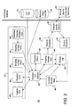
FIG. 2 summarizes the primary objects and data flows in the emulator application to
accomplish universal emulation. An Emulator Core Interface 20 provides an interface
between a user interface 22 and the lower, functional levels of the emulator 12. The
Emulator Core Interface 20 also accesses objects outside the emulator 12. For example, the
emulator core interface 20 can read an ICD file 24 upon user command, and generate the
appropriate message states in response. The emulator core interface 20 can also load a
Behavior Object Dynamically Linked Library (DLL) file 26 upon user command and enable
its execution.
A Sequence Object 28 receives commands and requests from the user interface via the
Emulator Core Interface 20. Specifically, the sequence object 28 handles encoding the
messages in the sequence, playing, pausing, and stopping an outgoing message sequence. A
Message Log 30 also receives commands and requests from the user interface via the
Emulator Core Interface 20. Specifically, the Message Log 30 records incoming and
outgoing messages upon user command and decodes the recorded messages.
An outgoing message state 40 is in communication with the sequence object 28. The
Outgoing Message State 40 encodes the human-readable field values into raw message data,
and sends the message data to the Transmit Dispatcher 38. The Outgoing Message State 40
also logs the message if the user enabled logging for this message. Typically, the emulator
application 12 will contain one of these message states for each outgoing message type
defined in the ICD file 24. Within the user interface 22, the Predefined Outgoing Messages
View 46 can copy a stored message to the appropriate Outgoing Message View 48. The User
Interface 22 is also comprised of a plurality of function dialog boxes, windows, and views as
further detailed below in FIGS. 3A-3P that permit the user to access and implement the
functionality of the emulator 12.
In a preferred embodiment, an Incoming Message Views 56 with in the user interface
22 display the fields in incoming messages in a human-readable format. The Incoming
Message Views 56 also display the raw data of incoming messages and a recording of the
most recent messages. The Incoming Message Views 56 request incoming message data from
the Emulator Core Interface 20. The Emulator Core Interface 20 passes these requests to the
appropriate Incoming Message State 44. If the user has marked a particular Incoming
Message State 44 for logging using the Logging View 62, the Incoming Message State 44
will send the message data to the Message Log 30 for recording purposes after receiving the
message data from the Receive Dispatcher 42. The Receive Dispatcher 42 receives the
message data from the Protocol-Specific Interface 32 which in turn is supplied the incoming
message data from the Protocol-Specific Driver and hardware 34.
Similarly, the Outgoing Message Views 48 enable the user to define outgoing
message data in a human-readable format. Like the Incoming Message Views 56, these
objects also display the message's raw data and a recording of the most recent messages.
These objects also display a "Send" button, so the user can send the message he defined on
command. The Predefined Outgoing Message View 46 enables the user to define the content
of numerous outgoing messages. The user can copy any of these messages to the appropriate
Outgoing Message View 48 at any time. The Outgoing Message Views 48 send user
commands and outgoing message data to the Emulator Core Interface 20. The Emulator Core
Interface 20 passes these commands and data to the appropriate Outgoing Message State 40.
If the user has marked a particular Outgoing Message State 40 for logging using the Logging
View 62, the Outgoing Message State 40 will send the message data to the Message Log 30
for recording purposes before sending the message data to the Transmit Dispatcher 38. When
the Transmit Dispatcher 38 receives message data from an Outgoing Message State 40, the
Transmit Dispatcher 38 sends the message data to the Protocol-Specific Interface 32. The
message data is subsequently directed to the Protocol-Specific Driver and hardware 34. How
exactly the Transmit Dispatcher does this depends on the third party driver currently in use as
would be appreciated by those of ordinary skill in the pertinent art.
The Logging View 62 enables the user to command the subject application to start
and stop a log, choose which message types to log, set a limit on the number of messages or
bytes to log, search a log for a particular field value or range of values, and save the log to a
file. The Logging View 62 passes user commands and requests to the Emulator Core
Interface 20, including when to start and stop logging, and which messages to log. The
Logging View 62 also queries the Emulator Core Interface 20 for the logged data. The
Emulator Core Interface 20 passes these commands and requests to the Message Log 30.
The Sequence View 84 enables the user to define a sequence of outgoing messages,
and to play, pause, and stop the sequence. The Sequence View 84 passes user commands and
requests to the Emulator Core Interface 20, including commands to start, pause, and stop the
sequence, and create, edit and delete a sequence. The Emulator Core Interface 20 passes
these commands and requests to the Sequence Object 28. While a Sequence Object 28 plays
a scenario, the Sequence Object 28 outputs messages to the appropriate Outgoing Message
States 40. From here, the Outgoing Message State 40 outputs the messages to the Transmit
Dispatcher 38.
A Transmit Dispatcher 38 receives outgoing message data from all the Outgoing
Message State objects 40 and sends the message data to the Protocol-Specific Interface 32.
The Receive Dispatcher 42 receives incoming message data from the Protocol-Specific
Interface 32 and determines the appropriate Incoming Message State 44 to send the incoming
message to. The Protocol-Specific Interface 32 also sends and receives data to and from the
Protocol Specific Driver 34 of the communication device currently in use on the computing
platform. The Incoming Message State 44 receives message data from the Receive
Dispatcher 42, which the incoming message state 44 then decodes, enabling the user interface
22 to access the value of the message fields through the Emulator Core Interface 20. The
Incoming Message State 44 also logs the message if the user enabled logging for this
message. Typically, the emulator 12 of the subject disclosure application will contain one of
these message states for each incoming message type defined in the ICD file 24.
The ICD file 24 contains an emulator-readable ICD detailing the interface
requirements between components in the system 10. The Emulator Core interface 20 reads
this file upon user command. The Behavior Object Exe File 26 is an optional executable
object that the user can "plug in" to the emulator 12 of the subject disclosure application.
Developers create behavior objects to add extra behavior to an emulation provided by the
emulator 12 of the subject disclosure. The behavior objects have access to all the core
services that the user interface has access to. For example without limitation, behavior
objects can read message data, modify message data, build sequences, start sequences, stop
sequences, start log, and stop logs. The Protocol-Specific Driver 34 and associated hardware
represents any third party drivers and interface devices that the emulator 12 may use to
communicate with the protocol the ICD file 24 defines. The Protocol-Specific Interface 32
initializes the protocol-specific hardware and sends and receives message data to and from
the Protocol Specific Driver 34 via Data Flow 36.
In another embodiment, the emulator can interface with external executable objects
written by other developers. Through these external executable objects, other developers can
"automate" the behavior of a particular emulation. For example, in the commercial aviation
situation, if the control tower's computer changes the airstrip that the tower wants the airliner
to land at, the airliner should change the heading it reports to the tower (because the airliner
would have to "aim" for a new airstrip).
For the purposes of providing protocol-specific functions and features to the user, the
subject disclosure details communication- and operating system-specific dialogs, views, and
other user interfaces as shown in FIGS. 3A-3P. It is envisioned that universal emulation may
be achieved by computing platforms of a high variety of hardware, software, and other
technical configuration as would be appreciated by one of ordinary skill in the pertinent art
based upon review of the subject disclosure.
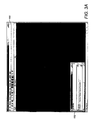
Referring to FIG. 3A, the preferred embodiment of the emulator runs on any Microsoft
Windows operating system and an status view screen is referred to generally by the reference
numeral 100. It is envisioned that the actual number and arrangement of the user interface
screens may vary according to the particular design and application. To launch the emulator
12, the user can start through the normal means of double-clicking on its file icon, or
selecting it from the <Start> Menu, if the <Start> menu is configured to do so. Following
startup, the main application window (not shown) appears, along with the status view as
shown in FIG. 3A. Preferably, the first user view to appear when the user starts the emulator
application or selects File→New is the Status View 100. Depending on the DLL files the
user installed when installing the emulator 12, the emulator 12 may use the TCP/IP as the
default communication protocol, as noted by the "New Core: Protocol = Internet
Protocol(IP)" text 102 in FIG. 3A. At this point, the emulator has typically not read an ICD
file; otherwise, the emulator would display the ICD file name and path next to the "Current
ICD File" in the same text status block. The ICD file defines which communication protocol
(such as, without limitation, TCP/IP or MIL-STD-1553) to use, and as such the user does not
have to be concerned with choosing a protocol.
Referring to FIG. 3B, a load ICD file dialog box is referred to generally by the
reference numeral 104. To load the ICD file 24, the user defines the ICD file to use by
selecting the menu item "File->Load Interface Control Document (ICD)," browsing for the
ICD file to load, and clicking "Open." After the emulator application loads the ICD file 24,
the component configuration dialog box 106 will pop up as shown in FIG. 3B1. The user
can choose the component or components to emulate (or monitor), and other protocol-specific
configuration data. After clicking "OK" in the component configuration dialog box
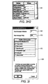
106, the emulator application loads the ICD file 24 and displays a preferences dialog box 108
as shown in FIG. 3B2. The preferences dialog box 108 allows the user to select the number
of decimal digits for real numbers.
The application window of the emulator application includes a "File->New" command,
chosen from the "File->New" menu item. The "File->New" command will close the current
emulation and create a new one. The new emulation will not have an ICD file 24. The user
can save the current emulation in an "emulator unique file" (.mii) by choosing "File→Save,"
or "File→Save As," or the save menu button. In a preferred embodiment, the emulator 12
writes the following information data items to the file when the user chooses this option: (i)
the ICD file path and file name; (ii) the content of the ICD; (iii) any configuration data that
the user has set, including the components currently emulated, and the communication
parameters for each component (for TCP/IP or UDP/IP protocols for example, the emulator
would save the IP address and port number for each component); (iv) all the predefined
outgoing messages that the user has defined; (v) all message sequences; (vi) the paths of the
Behavior Objects that the user has loaded; (vii) the sizes and positions of the message views;
and (viii) other internal configuration data.
The application window of the emulator application also includes a "File->Open"
command, chosen from the "File->Open" menu item, which enables the user to open an
emulation file (.mii) the user saved previously. After reading this file, the emulator 12
restores the emulation saved in the file.
In another embodiment, the emulator provides the capability to resolve
inconsistencies between the data stored in a .mii file and changes made to the associated ICD
file. For example, consider the following sequence of events: the user emulates the tower's
computer, creates a set of predefined "Destination Info" messages, saves the emulation in a
mii file and closes the emulator, changes the name of the "Precipitation Type" file to
"Precip. Type" in the ICD, and opens the mii file again with the emulator. The emulator
will sense the inconsistency between the saved predefined messages and the message type
defined in the ICD, and ask the user for help in resolving the inconsistency.
Referring to FIG. 3C, during emulation and monitoring, a typical in message view
screen 110 is shown. The In Message View Screen 110 displayed by the emulator
application 12 allows the user to view the following:
- Fields Grid: Field names and their decoded, human-readable values in the most
recently received message,
- Raw Data Grid: hexadecimal representation of the most recently received
message,
- History: a human-readable "history" of the value of the fields of previously
received messages.
Also, the In Message View 110 will display information about a field in a "tooltip"
window. This information includes:
- the field's name,
- human-readable value,
- hexadecimal value,
- binary value,
- the field's position in the message,
- the field's length,
- the field's type.
Other such information may be included in this tooltip window in the future. The
emulator application brings up this tooltip window automatically when the user rests the
mouse pointer on a field in the Fields Grid.
The "Bigger" and "Smaller" buttons horizontally resize the Fields Grid.
Each In Message View can also display multiple instances of a particular message
type in the Fields Grid in different columns. In other words, the In Message View can
display the most recent message data without overwriting previously displayed messages.
The user can identify an "overwrite field" for a particular In Message View. When the user
chooses an overwrite field, the In Message View will display multiple messages (in multiple
columns), rather than just one message in one column. If a new incoming message's
overwrite field has the same value as a previous message's overwrite field, the old message
data is overwritten with the new in the appropriate column. If the new message's overwrite
field does not have the same value as any other ones currently displayed, the emulator will
create a new column and write the message data there.
Referring to FIG. 3D, the In Message Configuration Dialog 120 (brought up by
clicking the "Config..." button) enables the user to configure: Overwrite fields; Logging
options; for the In Message View's Message History; Whether or not to display byte offsets
in the In Message View's Raw Data Grid; and How often to update the view with new
message data.
Referring to FIG. 3E, the Outgoing Message View 122 enables the user to manually
define the content of an outgoing message, and to send the outgoing message using the
emulator application 12. This view has many of the same properties as the In Message View.
As the user types in the values of the message's fields in the Fields Grid 124, the emulator 12
updates the hexadecimal representation of the message data in the Raw Data Grid 126.
Likewise, edits to the Raw Data Grid 126 will result in corresponding automatic updates to
the Fields grid 124. This view also keeps a history of transmitted messages, in human-readable
format. To transmit the currently defined message, the user simply clicks the
"Send" button 130. The Outgoing Message View 122 also has its own configuration dialog
view 132 (bring it up via the "Config..." button), displayed in FIG. 3E2. The configuration
dialog view 132 shares many of the same elements as the In Message Configuration Dialog.
Referring to FIG. 3F1, the Predefined Messages View 134 enables the user to define
the content of multiple "predefined" outgoing messages. The Predefined Messages View 134
will display the predefined messages appropriate for the Out Message View that the user
most recently put focus on. The user defines the content of a predefined message in the
Fields Grid 136 on the right side of the view 134. The "New Default" button 138 allows the
user to create a new predefined message with default data in the message fields (The ICD
defines the default value for all fields). The "New Copy" button 140 allows the user to create
a new predefined message whose content is copied from the currently selected predefined
message. The "New Current" button 142 allows the user to create a new predefined message
whose content is copied from the Out Message View.
Upon clicking these "New" buttons, the application allows the user to enter a name
for the new predefined message in a small dialog 144, shown in figure 3F2. The small dialog
144 provides a default name for the user. The user selects the predefined message to operate
on in the list box displayed in the bottom left hand comer of the view. The user is then able
to quickly setup an outgoing message by clicking the "Move" button, which copies the
content of the selected predefined message to the appropriate Out Message View. The user
can then modify the content of the Out Message View and/or send the content. Clicking the
"Send" button executes a "Move" as above, and also immediately sends the message. The
user can modify the comments of each Predefined Message in the edit box in the upper left
hand comer. These outgoing messages are saved when the user saves the emulation. This
functionality is designed to minimize manual data entry in repetitive message formatting,
allowing the user to define each message only once, and bring each up at will with a simple
button click.
Shown in FIG. 3G, the Component Configuration Dialog 146 will pop up
automatically when the user loads a new ICD file 24. The Component Configuration Dialog
146 enables the user to configure which components (from the ICD) the emulator application
12 shall emulate or monitor. In this example, this diagram displays the Component
Configuration Dialog for the IP Protocol. The user can configure which components he
wants to emulate, and the IP configuration parameters for the components (IP addresses and
port numbers). The emulator application will display other similar dialogs for each
communication protocol it supports. The Component Configuration Dialog 146 also pops up
if the user selects Control->Component Config at the menu option.
Shown in FIG. 3H, the Sequence View 148 enables the user to define a sequence of
outgoing messages and the delay between them. The user can bring up the Sequence View
148 by selecting the Sequence->Sequences menu option. The Sequence View 148 enables the
user to define sequences of outgoing messages. The "Sequence Grid" displays the time, post-send
time gap, message name and field values of each message in the sequence. At any time,
the user can choose to play, stop, or pause the sequence. The diagram 148 displays the Play
button 150, but the Stop button 152 and Pause 154 button are grayed out, since the scenario is
not currently playing. The combo box 156 labeled "Current Seq" enables the user to choose
the current sequence. The "New Seq" button 158 enables the user to create a new, blank
sequence. The "Delete Seq" 160 will delete the entire sequence currently chosen, and the
"Change Seq Name" 162 enables the user to change the name of the sequence currently
chosen. Referring to FIG. 3H2, a Message Grid Popup 164 provides information to the user
after a click on the Field Values column in a Message Sequence. This popup grid gives the
user a more complete description of the content of the selected message in the sequence.
Referring to Fig. 3I, an Interpolation Dialog is referred to generally by the reference
numeral 166. The "Number Messages Between" edit box 168 allows the user define how
many messages to insert between the selected messages in the sequence. The "Inter-Message
Delay" edit box 170 lets the user define the time delay between interpolated messages. The
"Fields to Interpolate" grid 172 lets the user identify which fields to interpolate. The subject
application prevents the user from selecting non-numeric fields (such as character strings or
Booleans). Clicking "OK" will cause the subject application to insert messages between the
ones chosen previously, and will interpolate smoothly the fields selected in the grid to reflect
a dynamically changing environment.
The Sequence View supports standard Copy, Cut, and Paste functions. That is, the
user can select a number of messages, copy or cut them to the clipboard, and paste them to
other places in the sequence. The user may even paste messages into a different sequence
they were not copied or cut from. The user can choose the Copy, Cut and Paste functions by
selecting the rows to copy or cut in the Sequence Grid, choosing Copy or Cut from the Edit
menu or the popup menu via a right-click, selecting the appropriate row in the grid to execute
the Paste operation, and choosing Paste from the Edit menu or the popup menu.
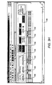
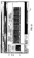
The Logging View 174 shown in FIG. 3J enables the user to record incoming and
outgoing messages, and enables the user to view these messages in a human-readable format.
The user can bring this view up by selecting Log->Message Log... or by clicking the "L"
icon on the toolbar underneath the Main Menu. The user can start and stop logging messages
with the button 176 marked "Press to begin recording." Upon activation, button 176 toggles
to read "Press to stop recording" to allow for cessation of recording. At any time, the user
can press the "Log All Messages" button 178 to log all message types or the "Log No
Messages" button 180 to log none, and choose which message types individually to log in the
"Messages to Log " grid 182.
The view displays the log in the grid in the center of the screen. It includes the time
Mimic logged the message, the component that transmitted or received it, whether or not
Mimic received or transmitted the message ("IN" or "OUT"), and finally the field names and
field values of the message.
The view 174 also displays the total number of messages logged, and the total number
of bytes in the logged messages. The user can set a limit on the amount of bytes or messages
logged by clicking the "Set log limit" button 184. The user can also set a limit for both the
byte count and number of messages simultaneously, and the emulator application 12 will stop
logging when the first of these limits is hit. The user can bring up the Message Log Details
View 186, shown in Figure 3J2, by choosing the "Log->Message Details..." menu option
from the main menu.
After logging completes, the user can command the emulator 12 to search for
messages in the log that contain a field whose value meets certain criteria. The user can
define this criteria through a dialog brought up by clicking the "Set Search Parameters"
button in the Log View. For example, the user can search the log for all Destination Info
messages whose Temperature field has a value of less than 59 degrees. After the user clicks
the "Set Search Parameters" button, the dialog that pops up enables the user to define all
these parameters. The user can then use the "Next" and "Prev" buttons to search through the
log for messages that meet this criteria.
By clicking the "Save log to file" button in the Log View, the user can save the log to
a text file. Before saving the log to a text file, the emulator application 12 gives the user a
choice to save the log in a variety of formats, such as a spreadsheet-readable file, or a more
human-readable text format. A "spreadsheet-readable" choice, for example, causes the
emulator application 12 to save the file in a tab-delimited format, and arranges the fields of
the message into columns, where each row stores a message. Most spreadsheet application
can read this format, thereby enabling the user to operate on the logged message data with all
the capabilities of spreadsheets, such as creating graphs and charts
The "Scroll grid with log" check box in the Log View enables the user to choose to
keep the most recent logged messages visible by scrolling the grid downward after messages
accumulate beyond the size of the grid.
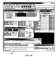
Referring to FIG. 3K, the Message Window Control View 200 allows the user to
choose to restore or bring to the top any message view, all outgoing or all incoming message
views of a component, or all message views of a component, depending on which radio
button on the left the user selects. Additional radio buttons may be provided as system
design can of course be particularized to specific user demands.
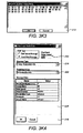
The user defines new messages or edits already-existing messages by bringing up the
"Message Definition" Dialog 216, shown in FIG 3K4. The user can choose "Insert a New
Message..." or "Edit Message..." from either the "Sequence" menu or the Sequence Grid's
popup menu (right click on the Sequence Grid to display the popup menu). In this dialog
216, the user chooses the Message Type 218 of the selected/new message, the content 224 of
the message, and the delay 220 between the selected/ new message and the next message in
the sequence. This dialog 216 also gives the user the ability to choose a Predefined Message
222 for the selected/new message.
By selecting multiple messages and bringing up the Message Definition Dialog 216,
the user can set all the selected messages to the content of the Message Definition Dialog 216
when the user clicks "OK." The user can also edit only the Post-Send Delay value 220 for
one or more messages by selecting the messages in the Sequence Grid and choosing "Edit
Post-Send Delay Time..." from the "Sequence" or popup menu. The Post-Send Delay
Dialog 226, shown in FIG. 3K5, is accessed through dialog 216.
Referring to FIG. 3K6, the "Loop Control" button 228 enables the user to choose the
number of times the sequence will repeat when played. The user can also choose to repeat
the sequence an infinite number of times. The Sequence View 228 displays the maximum
number of loops and the current loop count next to the "Loop Control" button.
If the user checks the "Play on Emulation Start" check box in the Sequence View and
saves the emulation, the sequence will play automatically upon loading the emulation file,
after the delay defined in the "Delay (msecs)" edit box. To make this happen, the user must
save the emulation to an emulation file. The "Interpolate" button in the Sequence View
brings up the Interpolation Dialog, shown in Figure 3I. Before pressing this button, the user
must select two messages in the sequence (the user can highlight message by clicking on a
cell in the left-most column). The Interpolation Dialog enables the user to insert messages in
between the selected messages, and smoothly increment the value of numeric message fields
in the inserted messages.
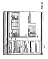
The ICD Editor Main View 240 show in FIG. 3L provides the principal functionality
associated with the creation, editing, and review of the ICD file 24 in the emulator 12. In a
preferred embodiment, the emulator 12 has the ability to apply stylesheets (like XSL) to an
ICD for easy display in a web browser. Preferably, the ICD file 24 is already in XML
format.
Preferably, the ICD Editor 240 currently has the Tower and Airliner ICD file loaded,
and may access several different functions from this one window. In the "High-level ICD
Information" section 242, the user can define the type of protocol used for this ICD by
clicking the "Edit" button 246. In the "Components" section 248, the user can create a new
component, edit an already-existing component, or delete a component. The "Transmitting
Component" box 250 and "Receiving Component" box 252 determine the message types that
the application lists in the list box 254 in the "Messages" section 256. In the "Messages"
section 256, the user can create a new message type, edit an already-existing message type, or
delete a message type (the application, for sake of brevity, calls a message type simply a
"message"). The "Transmitting Component" box 250 will transmit message types shown in
the list box. The "Receiving Component" box 252 will receive message types shown in the
list box.
The Message Fields 260 grid displays all fields in the message type currently
highlighted on the bottom left in the list box. In this example, the diagram shows the
message fields of the Destination Info message in the Tower and Airliner ICD. When editing
a message, the user can define comments for that message, and the diagram shows these
comments at the bottom left.
The grid 262 marked "Enumerations. shows the enumerations for the selected
message field within the Message Fields grid. The application 12 would not show any entries
in grid 262 if the selected field in the Fields Grid showed a type other than "ENUM." From
within the Field Editor Dialog, the user can define comments for that field, and the
application shows these comments at the bottom right. In this example, the selected Message
Field 264 is "Wind Direction", with entries in the "Enumerations:" field representing the
possible values for wind direction.
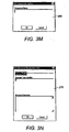
The Component Editor Dialog 266 shown in FIG. 3M enables the user to define the
component's name. If the user defined the protocol for this ICD as UDP or TCP, other
widgets may appear on this dialog. For example, if the user defined the protocol as 1553, an
edit box would appear that would enable the user to define the components Remote Terminal
address.
The user can bring this dialog up by clicking on the "New Component" or "Edit Component"
buttons in the Main View.
Referring to FIG. 3N, the Message Editor Dialog 270 is shown. The Message Editor
Dialog 270 enables the user to define the message type's name, the message type's ID, and
the message type comments. When using the UDP and TCP protocols, the emulator
application 12 uses message type IDs to identify the type of incoming message, which
enables it to parse the message correctly. The user can bring this dialog up by clicking on the
"New Message" or "Edit Message" buttons in the Main View.
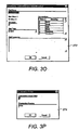
The Field Editor Dialog 272 shown in FIG. 30, enables the user to define a field's
name, bit-length, type, and comments. If the user chooses "REAL" as the field's type, the
dialog 272 also enables the user to define the field's LSB. The user can also define the
field's enumerations. The user can bring up this dialog by right clicking on a field in the
Fields Grid and choosing the "Insert" or "Edit" menu items.
Referring to FIG. 3P, the Enumeration Editor Dialog 274 enables the user to define
the text that the emulator application 12 will display for a field that has a particular integer
value (the "enumeration"). The user can bring up this dialog 274 from within the Field
Editor Dialog by right clicking on an enumeration within the Enumerations Grid and
choosing the appropriate menu item. It would be appreciated by those of ordinary skill in the
art that the ICD Editor could support a variety of features now known and later developed.
While using the Emulator 12, the user can Open, Save, and Save As a .mii file
through the standard file operations most windows applications provide for you in the File
menu in the upper left-hand corner of the application's main window. Open, Save, and Save
As read and write the Emulator Files, whose Windows extension is ".mii." When the user
saves the current emulation to a .mii file, the emulator writes to the file all the information
needed to replicate the same emulation in between emulator sessions, including: the ICD file
path; the content of the ICD; all message sequences defined by the user; all predefined
outgoing messages; the size and position of all message views; and other various
configuration data as would be appreciated by those of ordinary skill in the pertinent art.
After starting the emulator application 12, the user can choose to open an ICD file 24 (which
exists in XML text format) to begin emulating or monitoring a set of components. The user
can then save the session in a .mii file by choosing "Save" or "Save As." The "New"
command on the file menu simply creates a new, empty emulation. After choosing "New,"
the user must choose an ICD file 24 to load to begin emulating a component or set of
components. The user can do this with the "Load Interface Control Document" option on the
file menu.
The ICD Editor View 240 implements the file operations that windows applications
typically support on their file menu, including "New," "Open," "Save," and "Save As."
Open, Save, and Save As read and write the ICD File(s) 24, whose Windows extension is
".xml." Selecting "New" creates a new ICD file that the user can begin to define. When the
user chooses "Save" or "Save As," the ICD Editor formats the current user-defined ICD
information into a format readable by the emulator and the ICD Editor and saves it to a file.
"Save" simply saves it to the file it was last opened from or saved to. "Save As" allows the
user to choose the directory to which the ICD is saved. Selecting "Open" allows the user to
search for and open a previously-saved ICD File, thus allowing the user to view and further
edit the ICD. The ICD Editor formats the ICD file in "XML" format. XML stands for
"Extensible Markup Language." XML is an industry standard text format used widely in the
commercial software industry.
MENU AND TOOLBAR OPTIONS
The following Tables 1-10 describe the menu options, their resulting actions, and their
associated figures in a preferred embodiment of both the Emulator and the ICD Editor.
Toolbar buttons are also described, since applications written for Microsoft Windows
typically display the same options to the user in both menus and toolbar buttons. Note also
that Microsoft Windows supports two different menu types: the "Main Menu," "pull-down"
options spread across the top of most applications, and "context" or "pop-up" menus, which
the user can display by right-clicking on some views, dialogs, and windows. The application
will disable (i.e. "gray-out") many menu items listed below if the window that responds to
the user's menu item selection is not in focus. Figure 4 illustrates the
emulator toolbar icons
300 with a brief explanation thereof. Figure 5 illustrates the
ICD editor icons 400 with a brief
explanation thereof.
| "File" |
| Menu-Option | Action | Figure |
| Load Interface Control Document (ICD) File... | Enables the user to load an ICD File to begin emulation | 3B |
| New Emulation | Create a new emulation | 3A |
| Open Emulation... | Open an existing emulation file (.mii) and begin emulation | N/A |
| Close Emulation | Closes the current emulation | N/A |
| Save Emulation | Saves the current emulation to a .mii file | N/A |
| Save Emulation As... | Saves the current emulation to a .mii file of the user's choice | N/A |
| Load a New Behavior Object... | Loads a Behavior Object into the emulation | N/A |
| View Current Behavior Objects... | Bring up the Behavior Objects Control dialog | 3K1 |
| (Recent Files List) | Contains the names of the last several emulation files opened. Selecting one loads that particular emulation file. | N/A |
| Exit | Closes the Application | N/A |
| "Edit" |
| Menu Option | Action | Figure |
| Undo | Undo. | N/A |
| Cut | Cut the selected message or set of messages in an outgoing sequence to the clipboard. | N/A |
| Copy | Copy the selected message or set of messages in an outgoing sequence to the clipboard. | N/A |
| Paste | Paste messages from the clipboard to the selected position in the current outgoing message sequence. | N/A |
| "Message" |
| Menu Option | Action | Figure |
| Show info for current field | Bring up the Field Info View for the currently selected field in the Message View. | 3K2 |
| Show comments for current field | Bring up the Comments Dialog for the currently selected field in the Message View. | N/A |
| Show comments for current message | Bring up the Comments Dialog for the Message View currently in focus. | N/A |
| Send message | Send the message in the Message currently in focus. Grayed-out if message is incoming, | N/A |
| Configure view... | Bring up the Message View's Configuration Dialog. | 3D, 3E2 |
| Show Parsed Msg Data | Check to show the Message Data Grid, uncheck to hide it. | N/A |
| Show Raw Data | Check to show the Message Raw Data Grid, uncheck to hide it. | N/A |
| Show History | Check to show the MessageView's History, uncheck to hide it. | N/A |
| Raw Data Editor... | Bring up the Raw Data Editor. | 3K3 |
| Save as a Predefined Message | Enables the user to define a new Predefined Message based on the content of the current Message View. | N/A |
| "Control" |
| Menu Option | Action | Figure |
| Component Config... | Bring up the Component Configuration Dialog. | 3B1 |
| Preferences... | Bring up the Preferences Dialog | 3B2 |
| "Sequence" |
| Menu Option | Action | Figure |
| Sequence... | Bring up a new Sequence View | 3H |
| Insert New Message... | Bring up the Message Definition Dialog (defaulted to "Insert") | 3K4 |
| Edit Current Message... | Bring up the Message Definition Dialog (defaulted to "Edit") | 3K4 |
| Edit Post-Send Delay Time... | Bring up the Post-Send Delay Dialog | 3K5 |
| Cut | Cuts either:
1) The selected message or set of messages in a sequence to the clipboard,
or 2) The selected text to the clipboard | N/A |
| Copy | Copies either:
1) The selected message or set of messages in a sequence to the clipboard,
or 2) The selected text to the clipboard | N/A |
| Paste | Pastes either:
1) Message or a set of message into the selected position in a sequence from the clipboard
2) The selected text from the clipboard to the currently selected edit box | N/A |
| Play the Sequence | Play the current sequence from the beginning | N/A |
| Pause the Sequence | Pauses the current sequence | N/A |
| Stop the Sequence | Stops the currently sequence | N/A |
| Loop Control... | Brings up the Loop Control Dialog | 3K6 |
| Interpolate... | Brings up the Interpolation Dialog | 3I |
| "Log" |
| Menu Option | Action | Figure |
| Message Log... | Check to Bring up the Log View, uncheck to close it. | 3J |
| Message Details... | Bring up the message details for the currently selected message in the Log. | 3J2 |
| Begin Recording/Stop Recording | Begin Recording or Stop Recording, depending on the Log's current state. | N/A |
| Set Log Limit... | Bring up the "Set Logging Limits" dialog. | 3J3 |
| Set Search Parameters... | Bring up the "Log Search Parameters" dialog | 3J4 |
| Next | Highlight the next message that matches the search parameters defined in the "Log Search Parameters" | N/A |
| Previous | Highlight the previous message that matches the search parameters defined in the "Log Search Parameters" | N/A |
| Save Log to File... | Save the current message log to a file | N/A |
| "Protocol": The content of this menu is protocol-dependent; (TCP/IP: None)(UDP/IP: None)(COM/Serial Port: None)(MIL-STD-1553) |
| Menu Option | Action | Figure |
| Excalibur Functions... | Brings up the Excalibur Functions Dialog | N/A |
| Excalibur RT Config... | Brings up the Excalibur RT Configuration Dialog | N/A |
| BC Command Frame Report... | Brings up the Frame Report Dialog | N/A |
| "View" |
| Menu Option | Action | Figure |
| Toolbar | Check to show the toolbar, uncheck to hide it | N/A |
| Status | Check to show the status bar, uncheck to hide it | N/A |
| "Window" |
| Menu Option | Action | Figure |
| Cascade | Cascades all open windows | N/A |
| Tile | Tiles all open windows | N/A |
| Arrange Icons | Arranges all minimized windows | N/A |
| (Window List) | The contents of this list contain identifiers for all windows that appear within the application. The Emulator will update this list dynamically. Selecting one of these window identifiers will restore the identified window and bring it to the top of the Z-order. |
| "Help" |
| Menu Option | Action | Figure |
| Help Topics | Brings up the Mimi help documentation | N/A |
| About Mimic | Brings up the "About Box" Dialog | N/A |
The following Table 11 illustrates the emulator context menus of a preferred
embodiment. Context menus appear when the user right-clicks on some views and windows.
The tables identify the views/windows where context menus can appear, the main menu (the
menu displayed across the top of the application) that the context menu derives from, and any
differences between the main menu it derives from.
| View/Window | Main Menu Derived from | Differences |
| Log View | Log | "Message Log..." option is deleted." |
| Sequence Grid | Sequence | "Sequences..." option is deleted. |
| Incoming and Outgoing Message Views | Message | - None - |
The following Tables 12-16 illustrate the ICD editor mail menu options. Preferably,
the application will disable (i.e. "gray-out") many menu items listed below if the window that
responds to the user's menu item selection is not in focus.
| "File" |
| Menu Option | Action | Figure |
| New | Create a new ICD | 3L |
| Open | Open an existing ICD file (.xml) | N/A |
| Close | Closes the current ICD | N/A |
| Save | Save the current ICD | N/A |
| Save As... | Save the current ICD to a .xml file of the user's choice | N/A |
| (Recent Files List) | Contains the names of the last several ICD files opened. Selecting one loads that particular ICD file. | N/A |
| Exit | Closes the ICD Editor | N/A |
| "Edit" |
| Menu Option | Action | Figure |
| Undo | Not currently implemented (options remains disabled/grayed-out). | N/A |
| Cut | Cuts the selected message or set of messages, or field or selected fields, to the clipboard. | N/A |
| Copy | Copies the selected message or set of messages, or field or selected fields, to the clipboard. | N/A |
| Paste | Paste message(s) or Fields) from the clipboard. | N/A |
| "View" |
| Menu Option | Action | Figure |
| Toolbar | Check to show the toolbar, uncheck to hide it | N/A |
| Status | Check to show the status bar, uncheck to hide it | N/A |
| "Window" |
| Menu Option | Action | Figure |
| Cascade | Cascades all open windows | N/A |
| Tile | Tiles all open windows | N/A |
| Arrange Icons | Arranges all minimized windows | N/A |
| (Window List) | The contents of this list contain identifiers for all windows that appear within the application. The Emulator will update this list dynamically. Selecting one of these window identifiers will restore the identified window and bring it to the top of the Z-order. |
| "Help" |
| Menu Option | Action | Figure |
| Help Topics | Brings up the ICD Editorhelp documentation | N/A |
| About Mimic | Brings up the "About Box" Dialog | N/A |
The following Tables 17 and 18 illustrate the ICD editor main menu options.
Preferably, the application will disable (i.e. "gray-out") many menu items listed below if the
window that responds to the user's menu item selection is not in focus.
| Location: Main Window, Message Fields Grid |
| Menu Option | Action | Figure |
| Insert New Field | Brings up the Field Editor Dialog | 30 |
| Edit Current Field | Brings up the Field Editor Dialog | 30 |
| Delete Current Fields | Deletes the selected fields from the message. | N/A |
| Copy Field | Copies the selected fields to the clipboard | N/A |
| Cut Field | Cuts the selected fields to the clipboard | N/A |
| Paste Fields) from Clipboard | Inserts the fields on the clipboard into the selected position in the Message Fields Grid | N/A |
| Location: Main Window (anywhere except the Message Fields Grid) |
| Menu Option | Action | Figure |
| New Message | Brings up the Message Editor Dialog | 3N |
| Edit Current Message | Brings up the Message Editor Dialog | 3N |
| Delete Current Message | Deletes the selected fields from the message. | N/A |
| Copy Message | Copies the selected message to the clipboard | N/A |
| Cut Message | Cuts the selected message to the clipboard | N/A |
| Paste Messages from Clipboard | Inserts the message on the clipboard into the ICD. The ICD Editor will associate the new message with the Transmitting and Receiving Components displayed in the Main Window. | N/A |
It is envisioned that in order to use the emulator 12, a user would download the
emulator 12 on to a computer which is configured for use thereof. If the communication
protocols intended for use demand installation of interface cards and drivers, the installation
instructions of the vendor for that card must be followed prior to configuring the emulator 12.
Most computer manufactures configure their computers to support TCP/IP, UDP/IP and
COM/Serial Port communication protocols before shipment, so installing interface cards and
drivers for these protocols may be unnecessary. For other protocols, the user may need to
install the proper interface cards and drivers as would be known to those of ordinary skill in
the pertinent art.
In a preferred embodiment, the steps for installation and configuration of the
emulator
12, attached hereto in the appendix, are outlined below to illustrate a typical desirable
configuration although a multitude of acceptable configurations are readily available. The
installation and configuration consists of the following steps:
Preferably, the emulator 12 supports at least five communication protocols: ARINC
429, TCP/IP, UDP/IP, COM/Serial Port, and MIL-STD-1553B. It is envisioned that one
skilled in the pertinent art will appreciate the use in other communications protocols currently
in use or developed in the future after reviewing the subject disclosure.
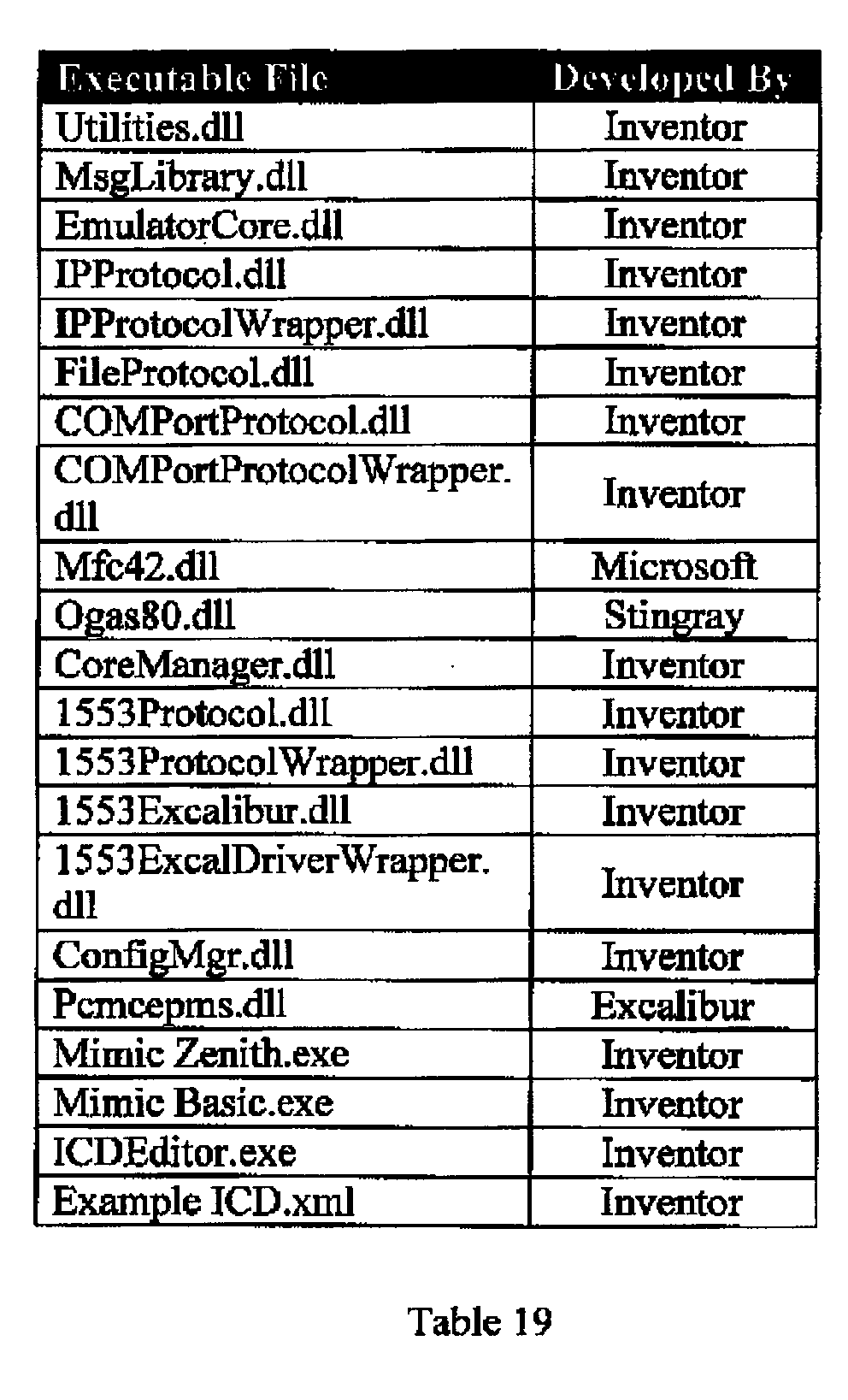
Still referring to the software appendix version of the
emulator 12 so that those having
ordinary skill in the art to which the disclosure appertains will more readily understand how
to make and use the same, reference may be had to the executable files contained herein as
detailed below in Table 19.
The Emulator 12 has two separate versions, embodied in 2 executable files: Mimic
Zenith.exe, and Mimic Basic.exe. Both are identical except that Mimic Basic cannot load
ICD files, only Emulation files, whereas Mimic Zenith can load both. It is envisioned that
some potential users will wish to have their Emulation files generated for them, and remain
unconcerned about ICD files. Mimic Basic would be appropriate for such a situation.
While the invention has been described with respect to preferred embodiments, those
skilled in the art will readily appreciate that various changes and/or modifications can be
made to the invention without departing from the spirit or scope of the invention as defined by
the appended claims.