EP1396644A1 - Device for connecting assembly rails - Google Patents
Device for connecting assembly rails Download PDFInfo
- Publication number
- EP1396644A1 EP1396644A1 EP03103254A EP03103254A EP1396644A1 EP 1396644 A1 EP1396644 A1 EP 1396644A1 EP 03103254 A EP03103254 A EP 03103254A EP 03103254 A EP03103254 A EP 03103254A EP 1396644 A1 EP1396644 A1 EP 1396644A1
- Authority
- EP
- European Patent Office
- Prior art keywords
- base part
- opening
- tether
- collar
- cone
- Prior art date
- Legal status (The legal status is an assumption and is not a legal conclusion. Google has not performed a legal analysis and makes no representation as to the accuracy of the status listed.)
- Granted
Links
- 239000000463 material Substances 0.000 claims description 5
- 238000009434 installation Methods 0.000 description 3
- 150000001875 compounds Chemical class 0.000 description 2
- 238000010276 construction Methods 0.000 description 2
- 238000005452 bending Methods 0.000 description 1
- 239000000470 constituent Substances 0.000 description 1
- 238000004519 manufacturing process Methods 0.000 description 1
- 238000000034 method Methods 0.000 description 1
- 238000004080 punching Methods 0.000 description 1
- 230000003014 reinforcing effect Effects 0.000 description 1
Images


Classifications
-
- F—MECHANICAL ENGINEERING; LIGHTING; HEATING; WEAPONS; BLASTING
- F16—ENGINEERING ELEMENTS AND UNITS; GENERAL MEASURES FOR PRODUCING AND MAINTAINING EFFECTIVE FUNCTIONING OF MACHINES OR INSTALLATIONS; THERMAL INSULATION IN GENERAL
- F16B—DEVICES FOR FASTENING OR SECURING CONSTRUCTIONAL ELEMENTS OR MACHINE PARTS TOGETHER, e.g. NAILS, BOLTS, CIRCLIPS, CLAMPS, CLIPS OR WEDGES; JOINTS OR JOINTING
- F16B3/00—Key-type connections; Keys
- F16B3/06—Key-type connections; Keys using taper sleeves
-
- F—MECHANICAL ENGINEERING; LIGHTING; HEATING; WEAPONS; BLASTING
- F16—ENGINEERING ELEMENTS AND UNITS; GENERAL MEASURES FOR PRODUCING AND MAINTAINING EFFECTIVE FUNCTIONING OF MACHINES OR INSTALLATIONS; THERMAL INSULATION IN GENERAL
- F16B—DEVICES FOR FASTENING OR SECURING CONSTRUCTIONAL ELEMENTS OR MACHINE PARTS TOGETHER, e.g. NAILS, BOLTS, CIRCLIPS, CLAMPS, CLIPS OR WEDGES; JOINTS OR JOINTING
- F16B7/00—Connections of rods or tubes, e.g. of non-circular section, mutually, including resilient connections
- F16B7/18—Connections of rods or tubes, e.g. of non-circular section, mutually, including resilient connections using screw-thread elements
-
- Y—GENERAL TAGGING OF NEW TECHNOLOGICAL DEVELOPMENTS; GENERAL TAGGING OF CROSS-SECTIONAL TECHNOLOGIES SPANNING OVER SEVERAL SECTIONS OF THE IPC; TECHNICAL SUBJECTS COVERED BY FORMER USPC CROSS-REFERENCE ART COLLECTIONS [XRACs] AND DIGESTS
- Y10—TECHNICAL SUBJECTS COVERED BY FORMER USPC
- Y10T—TECHNICAL SUBJECTS COVERED BY FORMER US CLASSIFICATION
- Y10T403/00—Joints and connections
- Y10T403/16—Joints and connections with adjunctive protector, broken parts retainer, repair, assembly or disassembly feature
- Y10T403/1616—Position or guide means
- Y10T403/1624—Related to joint component
-
- Y—GENERAL TAGGING OF NEW TECHNOLOGICAL DEVELOPMENTS; GENERAL TAGGING OF CROSS-SECTIONAL TECHNOLOGIES SPANNING OVER SEVERAL SECTIONS OF THE IPC; TECHNICAL SUBJECTS COVERED BY FORMER USPC CROSS-REFERENCE ART COLLECTIONS [XRACs] AND DIGESTS
- Y10—TECHNICAL SUBJECTS COVERED BY FORMER USPC
- Y10T—TECHNICAL SUBJECTS COVERED BY FORMER US CLASSIFICATION
- Y10T403/00—Joints and connections
- Y10T403/49—Member deformed in situ
- Y10T403/4941—Deformation occurs simultaneously with action of separate, diverse function, joint component
-
- Y—GENERAL TAGGING OF NEW TECHNOLOGICAL DEVELOPMENTS; GENERAL TAGGING OF CROSS-SECTIONAL TECHNOLOGIES SPANNING OVER SEVERAL SECTIONS OF THE IPC; TECHNICAL SUBJECTS COVERED BY FORMER USPC CROSS-REFERENCE ART COLLECTIONS [XRACs] AND DIGESTS
- Y10—TECHNICAL SUBJECTS COVERED BY FORMER USPC
- Y10T—TECHNICAL SUBJECTS COVERED BY FORMER US CLASSIFICATION
- Y10T403/00—Joints and connections
- Y10T403/49—Member deformed in situ
- Y10T403/4966—Deformation occurs simultaneously with assembly
Definitions
- the invention relates to a device for connecting mounting rails, in particular for connecting C-shaped mounting rails, wherein the device comprises a base part and at least one substantially angled tether comprises.
- the base part indicates at least one side wall has an opening for the passage of a fastening means, which is provided with a collar.
- the tether has an opening for the implementation of Fastening means, wherein the collar on the base part with the at least one opening in Tying part can be brought into engagement.
- DE 100 52 577 A1 discloses a connecting device for connecting mounting rails proposed, which has a base part and a tether.
- the tether is detachably connectable to the base part by a latching connection.
- the tether has four Locking cams, which in four symmetrically arranged around the mounting hole holes can be brought into engagement.
- a disadvantage of the known solution is that the Anbindemaschine only in, from the rest and Counter-locking elements predetermined positions can be attached to the base parts.
- the object of the invention is to provide a device for connecting mounting rails create, which has few components and a large space in the design of the designs to be created.
- the object is solved by the features of claim 1.
- the invention comprises a device for connecting mounting rails, in particular for connecting C-shaped Mounting rails, a base part and at least one substantially angular Attachment member.
- the base part has at least one side wall an opening for passage a fastener, which is provided with a collar.
- the tether part points an opening for the passage of the fastening means.
- the collar on the base part is with the at least one opening in the attachment part can be brought into engagement.
- the collar points at least partially formed as a clamping cone cone section.
- the base part is positioned along a first mounting rail and fixed thereto. Subsequently, the tether is attached to the base by bracing the fastener fastened, wherein by means of the cone portion a clamping connection between the two parts of the connecting device arises. Through the clamping cone is a backlash-free Centering of the compound created and the compound has a high torsional stiffness on.
- the tether may be in any angular position about the axis of the opening of the Base part are arranged.
- the collar has a cone portion that contacts the at least one sidewall the base part adjoins, and a tube-stub-like portion which abuts connects the cone section.
- the tube-stump-like portion of the collar serves as a centering means so that the tether part is connected to the base part.
- the cone section of the collar creates the positive connection between the tether and the base part when tightening the fastener.
- the at least one opening in the base part has an internal thread and the fastening means includes screwdrivers.
- the fastener engages in the internal thread one.
- This press connection is also for the Ausreiss the fastener advantageous because the threaded portion in the opening is supported on the base part by the tether.
- the length of the screw means is preferably chosen such that in the clamped state of the screw this the plane does not penetrate, which is formed by the inner surface of the corresponding side wall becomes.
- the tether can also on the sides, for example, a C-shaped mounting rail are arranged, which have no recesses.
- the angle of inclination of the cone section is less than 15 °, preferably less than 8 °.
- the size of the angle of the cone section are selected.
- the angle of the cone portion is preferably less than 8 °. This ensures that the tether with the opening can be pushed over the collar on the base part and the desired clamping or Press connection is created.
- the base part is made of a higher-strength material than the tether.
- the area of the opening in the tether can be in this embodiment in the Distort distortion of the fastener so strong that a positive connection is ensured without a large tightening torque on the fastener must be applied to create the connection.
- the outer surface of the cone section has a profiling, optionally a knurling on.
- the profiling With the profiling, the torsional stiffness of the connection between the Base part and the tether additionally improved.
- Fig. 1 shows an exploded view of the inventive device with a base part and a tether.
- the connecting device 1 comprises a U-shaped base part 2 and an angular attachment part 3.
- the base part 2 is made of a higher strength Material manufactured as the tether part 3.
- the base part 2 openings 5.1, 5.2 or 5.3 for carrying out a rail nut for fastening the base part 2 to a first Mounting rail on.
- so-called quick release nuts are used, as used in pipe installations in connection with mounting rails.
- an opening 6.1, 6.2 and 6.3 with a Provided internal thread 17.1, 17.2, or 17.3, in which the fastener, z. B. the Screw 7, for fixing the Anbindeteils 3 can engage the base part 2.
- the openings 6.1, 6.2 and 6.3 have a collar 10.1, 10.2 and 10.3, which has a cone section 8.2 and a tubular stump-like portion 9.2.
- the angle-shaped attachment part 3 has a first leg 11 and a second leg 12 on.
- On the first leg 11 is an opening 13 for the passage of the screw. 7 intended.
- On the second leg 12 is an opening 14 for carrying a rail nut provided so that a second mounting rail attached to the tether part 3 can be.
- this has in the lateral corner regions of the two legs 11 and 12 reinforcing plates 15.1 and 15.2 on.
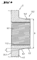
- Fig. 2 is a section through the base part is shown.
- the outer diameter D of the tubular stump-like Section 9.2 of the collar 10.1, 10.2 and 10.3 is smaller than the inner diameter d of the opening 13 of the Anbindeteils 3, so that the collar 10.1, 10.2 or 10.3 can penetrate into the opening 13.
- On the outside of the collar 10.1, 10.2 and 10.3 can be provided 16.2 knurling.
- FIG. 3 A section through the tether is shown in Fig. 3.
- the length L of the screw 7 is chosen such that in the assembled state of the base part 2 with the attachment part. 3 the foremost point 21 of the screw 7 does not penetrate the plane passing through the corresponding one Inside, z. B. the inside 22.2 of the side wall 4.2, is formed at the the Tying part 3 is connected to the base part 2. This will ensure that the connection device 1 can be arranged at any point of the mounting rail.
- Fig. 4 shows a detail X of Fig. 2.
- the collar 10.2 of the opening 6.2 has a Conical section 8.2, which adjoins the side wall 4.2 of the base part 2, as well as a tube-stump-like section 9.2, which adjoins the cone section 8.2.
- ⁇ of the cone section 8.2 is 7 °, wherein the cone section 8.2, relative to the axis of the opening 6.2, in the direction of the side wall 4.2 radially outward expands.
- the base part 2 is moved along the first mounting rail until the desired Position of the base part 2 is reached on the mounting rail. Subsequently, depending on Alignment of the mounting rail, in one of the openings 5.1, 5.2 or 5.3 of the base part. 2 introduced the rail nut. After the base 2 in the desired position on the first mounting rail is fixed, the tether part 3 on the side wall 4.1, 4.2 and 4.3, respectively the base part 2 is arranged to connect to the second mounting rail.
- the following Embodiments refer to a connection of the Anbindetteils 3 on the side wall 4.2 of the base part 2.
- the first leg 11 of the Anbindeteils 3 is used to the side wall 4.2, wherein the edge of the opening 13 in the tether part 3 slides over the cone section 8.2 and the opening 13 widens due to the different material pairing.
- the base part 2 and the tether 3 pressed together so that the connection between the two parts form- and is non-positive.
- a device for connecting mounting rails was created, which has few constituents.
- the tether can be arbitrary arranged aligned with the base part, giving a large space in the embodiment of the designs to be created.
- the with the inventive Device created connection between the connected mounting rails has a backlash-free centering and a high torsional rigidity, whereby the device high Can meet requirements.
Abstract
Description
Die Erfindung betrifft eine Vorrichtung zum Verbinden von Montageschienen, insbesondere zum Verbinden von C-förmigen Montageschienen, wobei die Vorrichtung ein Basisteil und zumindest ein im Wesentlichen winkelförmiges Anbindeteil umfasst. Das Basisteil weist an zumindest einer Seitenwand eine Öffnung zur Durchführung eines Befestigungsmittels auf, die mit einem Kragen versehen ist. Das Anbindeteil weist eine Öffnung zur Durchführung des Befestigungsmittels auf, wobei der Kragen am Basisteil mit der zumindest einen Öffnung im Anbindeteil in Eingriff bringbar ist.The invention relates to a device for connecting mounting rails, in particular for connecting C-shaped mounting rails, wherein the device comprises a base part and at least one substantially angled tether comprises. The base part indicates at least one side wall has an opening for the passage of a fastening means, which is provided with a collar. The tether has an opening for the implementation of Fastening means, wherein the collar on the base part with the at least one opening in Tying part can be brought into engagement.
Beispielsweise Rohrinstallationen werden an Montageschienen befestigt, die z. B. an einer Decke angeordnet sind. Zur Installation von Rohrleitungen werden auch im Raum erstellte Konstruktionen verwendet, die aus einzelnen, zumeist standardisierten Profilen erstellt werden. Solche Konstruktionen sind beispielsweise aus mehreren, miteinander verbundenen C-förmigen Montageschienen zusammengesetzt. Es sind verschiedene Vorrichtungen zum Verbinden von Montageschienen bekannt, die eine Erstellung von zwei- und dreidimensionalen Konstruktionen aus Montageschienen ermöglichen. Jede Art von Verbindung benötigt speziell auf diese Verbindung ausgebildete Verbindungselemente.For example, pipe installations are attached to mounting rails, z. B. at one Ceiling are arranged. For installation of pipelines are also created in the room Constructs that are created from individual, mostly standardized profiles. Such constructions are for example made of several, interconnected C-shaped Assembled mounting rails. There are various devices for Connect mounting rails known to create a two- and three-dimensional Allow constructions from mounting rails. Any kind of connection needed specially designed for this connection fasteners.
In der DE 100 52 577 A1 wird eine Verbindungsvorrichtung zum Verbinden von Montageschienen vorgeschlagen, die ein Basisteil und ein Anbindeteil aufweist. Das Anbindeteil ist durch eine Rastverbindung lösbar mit dem Basisteil verbindbar. Das Anbindeteil weist vier Rastnocken auf, die in vier symmetrisch um die Befestigungsöffnung angeordnete Bohrungen in Eingriff bringbar sind.In DE 100 52 577 A1 discloses a connecting device for connecting mounting rails proposed, which has a base part and a tether. The tether is detachably connectable to the base part by a latching connection. The tether has four Locking cams, which in four symmetrically arranged around the mounting hole holes can be brought into engagement.
Nachteilig an der bekannten Lösung ist, dass die Anbindeteile nur in den, von den Rast- und Gegenrastelementen vorgegebenen Positionen an den Basisteilen befestigt werden können. A disadvantage of the known solution is that the Anbindeteile only in, from the rest and Counter-locking elements predetermined positions can be attached to the base parts.
Werden die vorgenannten Anbindeteile ohne Rast- und Gegenrastmittel an den Basisteilen befestigt, weist die geschaffene Verbindung eine ungenügende Torsionssteifigkeit auf.Be the abovementioned Anbindeteile without latching and counter-locking means on the base parts attached, the created connection has insufficient torsional rigidity.
Aufgabe der Erfindung ist es, eine Vorrichtung zum Verbinden von Montageschienen zu schaffen, die wenige Bestandteile aufweist und einen grossen Freiraum in der Ausgestaltung der zu erstellenden Konstruktionen ermöglicht.The object of the invention is to provide a device for connecting mounting rails create, which has few components and a large space in the design of the designs to be created.
Die Aufgabe ist durch die Merkmale des Anspruchs 1 gelöst. Gemäss der Erfindung umfasst
eine Vorrichtung zum Verbinden von Montageschienen, insbesondere zum Verbinden von C-förmigen
Montageschienen, ein Basisteil und zumindest ein im Wesentlichen winkelförmiges
Anbindeteil. Das Basisteil weist an zumindest einer Seitenwand eine Öffnung zur Durchführung
eines Befestigungsmittels auf, die mit einem Kragen versehen ist. Das Anbindeteil weist
eine Öffnung zur Durchführung des Befestigungsmittels auf. Der Kragen am Basisteil ist mit
der zumindest einen Öffnung im Anbindeteil in Eingriff bringbar. Der Kragen weist zumindest
bereichsweise einen als Klemmkonus ausgebildeten Konusabschnitt auf.The object is solved by the features of
Das Basisteil wird entlang einer ersten Montageschiene positioniert und an dieser fixiert. Anschliessend wird das Anbindeteil an dem Basisteil durch Verspannen des Befestigungsmittels befestigt, wobei mittels des Konusabschnitts eine Klemmverbindung zwischen den beiden Teilen der Verbindungsvorrichtung entsteht. Durch den Klemmkonus wird eine spielfreie Zentrierung der Verbindung geschaffen und die Verbindung weist eine hohe Torsionssteifigkeit auf. Das Anbindeteil kann in jeder Winkelposition um die Achse der Öffnung des Basisteils angeordnet werden. Damit können die zu verbindenden Montageschienen beliebig ausgerichtet miteinander verbunden und müssen nicht in einem festen Raster zueinander angeordnet werden.The base part is positioned along a first mounting rail and fixed thereto. Subsequently, the tether is attached to the base by bracing the fastener fastened, wherein by means of the cone portion a clamping connection between the two parts of the connecting device arises. Through the clamping cone is a backlash-free Centering of the compound created and the compound has a high torsional stiffness on. The tether may be in any angular position about the axis of the opening of the Base part are arranged. Thus, the mounting rails to be connected arbitrarily aligned with each other and do not have to be in a fixed grid to each other to be ordered.
Vorzugsweise weist der Kragen einen Konusabschnitt, der sich an die zumindest eine Seitenwand des Basisteils anschliesst, und einen rohrstumpfartigen Abschnitt auf, der sich an den Konusabschnitt anschliesst. Der rohrstumpfartigen Abschnitt des Kragens dient als Zentriermittel damit das Anbindeteil geführt an das Basisteil angeschlossen wird. Der Konusabschnitt des Kragens schafft die formschlüssige Verbindung zwischen dem Anbindeteil und dem Basisteil beim Verspannen des Befestigungsmittels.Preferably, the collar has a cone portion that contacts the at least one sidewall the base part adjoins, and a tube-stub-like portion which abuts connects the cone section. The tube-stump-like portion of the collar serves as a centering means so that the tether part is connected to the base part. The cone section of the collar creates the positive connection between the tether and the base part when tightening the fastener.
Bevorzugt weist die zumindest eine Öffnung im Basisteil ein Innengewinde auf und das Befestigungsmittel umfasst Schraubmittel. Das Befestigungsmittel greift in das Innengewinde ein. Bei der Verspannung des Befestigungsmittels wird die Öffnung im Anbindeteil über den Konusabschnitt am Kragen des Basisteils gezogen, was den Formschluss zwischen den beiden Teilen in bevorzugter Art und Weise sicherstellt. Diese Pressverbindung ist zudem für das Ausreissverhalten des Befestigungsmittels vorteilhaft, da der Gewindebereich in der Öffnung am Basisteil durch das Anbindeteil gestützt wird. Die Länge des Schraubmittels ist vorzugsweise derart gewählt, dass im verspannten Zustand des Schraubmittels dieses die Ebene nicht durchdringt, die durch die Innenfläche der entsprechenden Seitenwand gebildet wird. Somit kann das Anbindeteil auch an den Seiten beispielsweise einer C-förmigen Montageschiene angeordnet werden, die keine Ausnehmungen aufweisen.Preferably, the at least one opening in the base part has an internal thread and the fastening means includes screwdrivers. The fastener engages in the internal thread one. When tightening the fastener, the opening in the tether over the Taper section pulled on the collar of the base part, which the positive connection between the ensures both parts in a preferred manner. This press connection is also for the Ausreissverhalten the fastener advantageous because the threaded portion in the opening is supported on the base part by the tether. The length of the screw means is preferably chosen such that in the clamped state of the screw this the plane does not penetrate, which is formed by the inner surface of the corresponding side wall becomes. Thus, the tether can also on the sides, for example, a C-shaped mounting rail are arranged, which have no recesses.
Vorteilhafterweise beträgt der Neigungswinkel des Konusabschnitts weniger als 15°, vorzugsweise weniger als 8°. In Abhängigkeit der Verformbarkeit der zur Fertigung des Basisteils, beziehungsweise des Anbindeteils gewählten Materials kann die Grösse des Winkels des Konusabschnitts gewählt werden. Für Teile die aus einem Blech, beispielsweise in einem Stanz-/Biegeverfahren, gefertigt wurden, beträgt der Winkel des Konusabschnitts vorzugsweise weniger als 8°. Damit ist gewährleistet, dass das Anbindeteil mit dessen Öffnung über den Kragen am Basisteil geschoben werden kann und die gewünschte Klemm- beziehungsweise Pressverbindung geschaffen wird.Advantageously, the angle of inclination of the cone section is less than 15 °, preferably less than 8 °. Depending on the deformability of the production of the base part, or the Anbindeteils selected material, the size of the angle of the cone section are selected. For parts of a sheet, for example, in one Punching / bending process, the angle of the cone portion is preferably less than 8 °. This ensures that the tether with the opening can be pushed over the collar on the base part and the desired clamping or Press connection is created.
Vorzugsweise ist das Basisteil aus einem höherfestem Werkstoff als das Anbindeteil gefertigt. Der Bereich der Öffnung im Anbindeteil kann sich bei dieser Ausführungsform bei der Verspannung des Befestigungsmittels derart stark verformen, dass eine formschlüssige Verbindung gewährleistet ist, ohne dass ein grosses Anzugsmoment auf das Befestigungsmittel zur Erstellung der Verbindung aufgebracht werden muss.Preferably, the base part is made of a higher-strength material than the tether. The area of the opening in the tether can be in this embodiment in the Distort distortion of the fastener so strong that a positive connection is ensured without a large tightening torque on the fastener must be applied to create the connection.
Bevorzugt weist die Aussenfläche des Konusabschnitts eine Profilierung, optional eine Rändelung auf. Mit der Profilierung wird die Torsionssteifigkeit der Verbindung zwischen dem Basisteil und dem Anbindeteil zusätzlich verbessert.Preferably, the outer surface of the cone section has a profiling, optionally a knurling on. With the profiling, the torsional stiffness of the connection between the Base part and the tether additionally improved.
Aus der nachfolgenden Detailbeschreibung und der Gesamtheit der Patentansprüche ergeben sich weitere vorteilhafte Ausführungsformen und Merkmalskombinationen der Erfindung.From the following detailed description and the totality of the claims result further advantageous embodiments and feature combinations of the invention.
Die Erfindung wird nachstehend anhand eines Ausführungsbeispieles näher erläutert. Es zeigen:
- Fig. 1
- eine Explosionsdarstellung der erfindungsgemässen Vorrichtung mit einem Basisteil und einem Anbindeteil;
- Fig. 2
- einen Schnitt durch das Basisteil;
- Fig. 3
- einen Schnitt durch das Anbindeteil; und
- Fig. 4
- ein Detailausschnitt X der Fig. 2.
- Fig. 1
- an exploded view of the inventive device with a base part and a tether part;
- Fig. 2
- a section through the base part;
- Fig. 3
- a section through the tethering; and
- Fig. 4
- a detail X of Fig. 2.
Grundsätzlich sind in den Figuren gleiche Teile mit den gleichen Bezugszeichen versehen.Basically, the same parts are provided with the same reference numerals in the figures.
Fig. 1 stellt eine Explosionsdarstellung der erfindungsgemässen Vorrichtung mit einem Basisteil
und einem Anbindeteil dar. Die Verbindungsvorrichtung 1 umfasst ein U-förmiges Basisteil
2 und ein winkelförmiges Anbindeteil 3. Das Basisteil 2 ist aus einem höherfesteren
Werkstoff als das Anbindeteil 3 gefertigt.Fig. 1 shows an exploded view of the inventive device with a base part
and a tether. The connecting
An allen drei Seitenwänden 4.1, 4.2 und 4.3 weist das Basisteil 2 Öffnungen 5.1, 5.2 oder 5.3
zur Durchführung einer Schienenmutter zur Befestigung des Basisteils 2 an einer ersten
Montageschiene auf. Vorzugsweise werden sogenannte Schnellspannmuttern verwendet,
wie sie bei Rohrinstallationen im Zusammenhang mit Montageschienen Anwendung finden.
Des Weiteren ist an jeder Seitenwand 4.1, 4.2 und 4.3 eine Öffnung 6.1, 6.2 und 6.3 mit einem
Innengewinde 17.1, 17.2, bzw. 17.3 vorgesehen, in die das Befestigungsmittel, z. B. die
Schraube 7, zur Befestigung des Anbindeteils 3 an dem Basisteil 2 eingreifen kann. Die Öffnungen
6.1, 6.2 und 6.3 weisen einen Kragen 10.1, 10.2 und 10.3 auf, der einen Konusabschnitt
8.2 und einen rohrstumpfartigen Abschnitt 9.2 aufweist.On all three side walls 4.1, 4.2 and 4.3, the
Das winkelförmige Anbindeteil 3 weist einen ersten Schenkel 11 und einen zweiten Schenkel
12 auf. An dem ersten Schenkel 11 ist eine Öffnung 13 zur Durchführung der Schraube 7
vorgesehen. An dem zweiten Schenkel 12 ist eine Öffnung 14 zur Durchführung einer Schienenmutter
vorgesehen, damit eine zweite Montageschiene an dem Anbindeteil 3 befestigt
werden kann. Zur Erhöhung der Traglast des winkelförmigen Anbindeteils 3 weist dieses in
den seitlichen Eckbereichen der beiden Schenkel 11 und 12 Verstärkungsbleche 15.1 und
15.2 auf.The angle-shaped
In Fig. 2 ist ein Schnitt durch das Basisteil gezeigt. Der Aussendurchmesser D des rohrstumpfartigen
Abschnitts 9.2 der Kragen 10.1, 10.2 und 10.3 ist kleiner als der Innendurchmesser
d der Öffnung 13 des Anbindeteils 3 ausgebildet, so dass der Kragen 10.1, 10.2 bzw.
10.3 in die Öffnung 13 eindringen kann. An der Aussenseite der Kragen 10.1, 10.2 und 10.3
kann eine Rändelung 16.2 vorgesehen sein.In Fig. 2 is a section through the base part is shown. The outer diameter D of the tubular stump-like
Section 9.2 of the collar 10.1, 10.2 and 10.3 is smaller than the inner diameter
d of the
Ein Schnitt durch das Anbindeteil ist in Fig. 3 dargestellt. Die Länge L der Schraube 7 ist
derart gewählt, dass im zusammengesetzten Zustand des Basisteils 2 mit dem Anbindeteil 3
der vorderste Punkt 21 der Schraube 7 nicht die Ebene durchdringt, die durch die entsprechende
Innenseite, z. B. die Innenseite 22.2 der Seitenwand 4.2, gebildet wird, an der das
Anbindeteil 3 an dem Basisteil 2 angeschlossen wird. So wird gewährleistet, dass die Verbindungsvorrichtung
1 an jeder Stelle der Montageschiene angeordnet werden kann.A section through the tether is shown in Fig. 3. The length L of the screw 7 is
chosen such that in the assembled state of the
Fig. 4 zeigt einen Detailausschnitt X der Fig. 2. Der Kragen 10.2 der Öffnung 6.2 weist einen
Konusabschnitt 8.2, der sich an die Seitenwand 4.2 des Basisteils 2 anschliesst, sowie einen
rohrstumpfartigen Abschnitt 9.2 auf, der sich an den Konusabschnitt 8.2 anschliesst. Der
Neigungswinkel α des Konusabschnitts 8.2 beträgt 7°, wobei sich der Konusabschnitt 8.2,
bezogen auf die Achse der Öffnung 6.2, in Richtung der Seitenwand 4.2 radial nach aussen
aufweitet.Fig. 4 shows a detail X of Fig. 2. The collar 10.2 of the opening 6.2 has a
Conical section 8.2, which adjoins the side wall 4.2 of the
Das Basisteil 2 wird entlang der ersten Montageschiene verschoben, bis die gewünschte
Position des Basisteils 2 an der Montageschiene erreicht ist. Anschliessend wird, je nach
Ausrichtung der Montageschiene, in einer der Öffnungen 5.1, 5.2 oder 5.3 des Basisteils 2
die Schienenmutter eingeführt. Nachdem das Basisteil 2 in der gewünschten Position an der
ersten Montageschiene fixiert ist, wird das Anbindeteil 3 an der Seitenwand 4.1, 4.2 bzw. 4.3
des Basisteils 2 angeordnet, an der die zweite Montageschiene anschliessen soll. Die nachfolgenden
Ausführungen beziehen sich auf einen Anschluss des Anbindetteils 3 an der Seitenwand
4.2 des Basisteils 2. Mittels dem rohrstumpfartigen Abschnitt 9.2 am Kragen 10.2,
der in die Öffnung 13 des Schenkels 11 des Anbindeteils 2 eindringt, wird das Anbindeteil 2
in Richtung des Basisteils 2 geführt. Sobald der, der Seitenwand 4.2 zugewandte, Rand der
Öffnung 13 an dem Konusabschnitt 8.2 anliegt, wird die Schraube 7 mit dem Innengewinde
der Öffnung 6.2 in der Seitenwand 4.2 in Eingriff gebracht. Das Anbindeteil 3 wird durch
Drehen um die Längsachse der Schraube 7 in die Position gebracht, in der die zweite Montageschiene
an die erste Montageschiene anschliessen. Beim Verspannen der Schraube 7
wird der erste Schenkel 11 des Anbindeteils 3 an die Seitenwand 4.2 herangezogen, wobei
sich der Rand der Öffnung 13 im Anbindeteil 3 über den Konusabschnitt 8.2 schiebt und sich
die Öffnung 13 infolge der unterschiedlichen Werkstoffpaarung aufweitet. Bereits bei einem
Anzugsmoment an der Schraube 7 von etwa 40 Nm werden das Basisteil 2 und das Anbindeteil
3 miteinander verpresst, so dass die Verbindung zwischen den beiden Teilen form-
und kraftschlüssig ist.The
Zusammenfassend ist festzustellen, dass eine Vorrichtung zum Verbinden von Montageschienen geschaffen wurde, die wenige Bestandteile aufweist. Das Anbindeteil kann beliebig ausgerichtet an dem Basisteil angeordnet werden, was einen grossen Freiraum in der Ausgestaltung der zu erstellenden Konstruktionen ermöglicht. Die mit der erfindungsgemässen Vorrichtung geschaffene Verbindung zwischen den verbundenen Montageschienen weist eine spielfreie Zentrierung und eine hohe Torsionssteifigkeit auf, womit die Vorrichtung hohen Anforderungen genügen kann.In summary, it should be noted that a device for connecting mounting rails was created, which has few constituents. The tether can be arbitrary arranged aligned with the base part, giving a large space in the embodiment of the designs to be created. The with the inventive Device created connection between the connected mounting rails has a backlash-free centering and a high torsional rigidity, whereby the device high Can meet requirements.
Claims (6)
Applications Claiming Priority (2)
| Application Number | Priority Date | Filing Date | Title |
|---|---|---|---|
| DE10240998A DE10240998B3 (en) | 2002-09-05 | 2002-09-05 | Device for connecting mounting rails |
| DE10240998 | 2002-09-05 |
Publications (2)
| Publication Number | Publication Date |
|---|---|
| EP1396644A1 true EP1396644A1 (en) | 2004-03-10 |
| EP1396644B1 EP1396644B1 (en) | 2005-05-11 |
Family
ID=29719539
Family Applications (1)
| Application Number | Title | Priority Date | Filing Date |
|---|---|---|---|
| EP03103254A Expired - Lifetime EP1396644B1 (en) | 2002-09-05 | 2003-08-30 | Device for connecting assembly rails |
Country Status (5)
| Country | Link |
|---|---|
| US (1) | US6929227B2 (en) |
| EP (1) | EP1396644B1 (en) |
| AT (1) | ATE295485T1 (en) |
| DE (2) | DE10240998B3 (en) |
| ES (1) | ES2240912T3 (en) |
Cited By (1)
| Publication number | Priority date | Publication date | Assignee | Title |
|---|---|---|---|---|
| US7805541B2 (en) | 2004-10-27 | 2010-09-28 | Dr. Johannes Heidenhain Gmbh | Modular numerical control having low-jitter synchronization |
Families Citing this family (14)
| Publication number | Priority date | Publication date | Assignee | Title |
|---|---|---|---|---|
| GB2375289B (en) * | 1998-12-30 | 2002-12-31 | Apw Electronics Ltd | Cabinet |
| US7717376B2 (en) * | 2006-10-17 | 2010-05-18 | Sparks Jr Douglas M | Bracket devices and systems |
| DE102007010236B4 (en) * | 2007-03-02 | 2008-11-20 | Toposys Topographische Systemdaten Gmbh | Device and method for distance determination by means of light pulses |
| US20080229699A1 (en) * | 2007-03-21 | 2008-09-25 | Unistrut International Corporation | Fittings for metal framing |
| US20080245936A1 (en) * | 2007-04-03 | 2008-10-09 | Joseph Dominic Frascella | Pocketed drape pole truss hanger |
| US20100050587A1 (en) * | 2008-08-28 | 2010-03-04 | Stoffel Neal J | Modular sickle bar with integrated locking system |
| US20100269919A1 (en) * | 2009-04-27 | 2010-10-28 | Curtis-Toledo Inc. | Air receiver tank with removable top plates |
| US8870163B2 (en) * | 2011-03-25 | 2014-10-28 | John E. Regan | Bracket system and method |
| US8959771B2 (en) | 2011-08-31 | 2015-02-24 | Friedrich Air Conditioning Co., Ltd. | Method of constructing a shell for a room air conditioner/heat pump with lateral strength |
| US9534371B2 (en) * | 2012-03-27 | 2017-01-03 | Steven G. Judd | Framing system for steel stud framing |
| JP2015003575A (en) * | 2013-06-20 | 2015-01-08 | トヨタ紡織株式会社 | Manufacturing method of vehicle seat |
| NL2011193C2 (en) * | 2013-07-18 | 2015-01-21 | Walraven Holding Bv J Van | Attachment of channel elements. |
| US20160051044A1 (en) * | 2014-08-25 | 2016-02-25 | Pro-Mart Industries, Inc. | Shelving brace |
| USD988838S1 (en) * | 2021-06-18 | 2023-06-13 | Chiao-Yin CHANG | Corner bracket |
Citations (2)
| Publication number | Priority date | Publication date | Assignee | Title |
|---|---|---|---|---|
| US4461366A (en) * | 1981-09-18 | 1984-07-24 | Honda Motor Co., Ltd. | Frame for motorcycles |
| US20020054788A1 (en) * | 2000-10-23 | 2002-05-09 | Armin Hoffmann | Connection element |
Family Cites Families (10)
| Publication number | Priority date | Publication date | Assignee | Title |
|---|---|---|---|---|
| FR2293893A1 (en) * | 1974-12-12 | 1976-07-09 | Telemecanique Electrique | FRAME FOR METAL CABINET |
| US5167478A (en) * | 1990-04-03 | 1992-12-01 | Kennametal Inc. | Tool holder with radial tool change mechanism |
| US5193643A (en) * | 1991-07-25 | 1993-03-16 | Saturn Corporation | Nut and retainer assembly |
| DE4243185A1 (en) * | 1992-12-19 | 1994-06-23 | Hilti Ag | Fastening device |
| US5713651A (en) * | 1996-02-27 | 1998-02-03 | Mcquay International | Modular frame assembly for an equipment cabinet |
| US5893694A (en) * | 1997-10-10 | 1999-04-13 | Eaton Corporation | Caged nut fastener |
| GB2375289B (en) * | 1998-12-30 | 2002-12-31 | Apw Electronics Ltd | Cabinet |
| US6260197B1 (en) * | 1999-04-09 | 2001-07-17 | Jackson Products, Inc. | Welding helmet with conical pivoting mechanism for head gear strap |
| US6494639B1 (en) * | 1999-05-01 | 2002-12-17 | Universal Services, Inc. | Primary connector for pre-cast structures |
| US6688712B2 (en) * | 2001-07-13 | 2004-02-10 | Carrier Corporation | Detachable frame for coil removal |
-
2002
- 2002-09-05 DE DE10240998A patent/DE10240998B3/en not_active Expired - Fee Related
-
2003
- 2003-08-30 DE DE50300530T patent/DE50300530D1/en not_active Expired - Lifetime
- 2003-08-30 EP EP03103254A patent/EP1396644B1/en not_active Expired - Lifetime
- 2003-08-30 ES ES03103254T patent/ES2240912T3/en not_active Expired - Lifetime
- 2003-08-30 AT AT03103254T patent/ATE295485T1/en active
- 2003-09-04 US US10/654,681 patent/US6929227B2/en not_active Expired - Lifetime
Patent Citations (2)
| Publication number | Priority date | Publication date | Assignee | Title |
|---|---|---|---|---|
| US4461366A (en) * | 1981-09-18 | 1984-07-24 | Honda Motor Co., Ltd. | Frame for motorcycles |
| US20020054788A1 (en) * | 2000-10-23 | 2002-05-09 | Armin Hoffmann | Connection element |
Cited By (1)
| Publication number | Priority date | Publication date | Assignee | Title |
|---|---|---|---|---|
| US7805541B2 (en) | 2004-10-27 | 2010-09-28 | Dr. Johannes Heidenhain Gmbh | Modular numerical control having low-jitter synchronization |
Also Published As
| Publication number | Publication date |
|---|---|
| DE50300530D1 (en) | 2005-06-16 |
| ATE295485T1 (en) | 2005-05-15 |
| US6929227B2 (en) | 2005-08-16 |
| EP1396644B1 (en) | 2005-05-11 |
| ES2240912T3 (en) | 2005-10-16 |
| US20040124319A1 (en) | 2004-07-01 |
| DE10240998B3 (en) | 2004-01-08 |
Similar Documents
| Publication | Publication Date | Title |
|---|---|---|
| EP1396644B1 (en) | Device for connecting assembly rails | |
| DE2556048C2 (en) | Centering and fastening device for the assembly of two sheet metal elements | |
| DE3325469A1 (en) | BOLTED NODE CONNECTION | |
| AT395203B (en) | CONNECTING ELEMENT FOR CONNECTING A PIPE TO A SPHERICAL COMPONENT | |
| DE202013005582U1 (en) | System comprising a carrier component | |
| EP1396645B1 (en) | Device for assembling mounting rails at an angle | |
| WO2004062987A1 (en) | Assembly for connecting a tubular first component to a second component | |
| EP1388308B1 (en) | Assembly with a first and second constuction part and a mounting bracket for temporary holding and fixing the first construction part to the second construction part. | |
| EP1388620B1 (en) | Connection element for a mounting system | |
| DE3339513C2 (en) | Plastic fastening element | |
| EP4080069B1 (en) | System for fixing | |
| DE2916003A1 (en) | Fixing device connecting two building components - has threaded rod held by one unit while another prevents motion of fixer in rail | |
| DE2441297A1 (en) | Universal pipe hanger - two semi circular clamp pieces and screw connection fitting to U shaped hanger | |
| DE102011002031A1 (en) | Anchoring device for fastening a component to a carrier element | |
| DE3700619C2 (en) | ||
| DE102009000649A1 (en) | Mounting device i.e. rail nut, for mounting threaded rod at C-shaped assembly rail in rail system utilized in area of building services, has connecting section with sectionally running receiving bore for receiving bar element | |
| DE10236550A1 (en) | Holding device for a cable harness shoe element | |
| DE102005051215B4 (en) | Adjustable attachment of vehicle doors | |
| EP2017484B1 (en) | Connecting device | |
| DE102020214127A1 (en) | Device for fastening to a component and a method for fastening a device to a component | |
| DE202022100401U1 (en) | locking bar | |
| DE19835764A1 (en) | Profile bar connection device for engineering structures comprises undercut bar grooves for engagement by clamp and finalized by screw insertion. | |
| EP3865717A1 (en) | Telescopic strut | |
| EP4256210A1 (en) | Washer for covering slots | |
| DE102005020069A1 (en) | System for mounting seat rails on floor plates in vehicles comprises tolerance washer fitted on bolt which is passed through bore in rail into nut under plate, bolt then being fastened using tolerance compensation provided by washer |
Legal Events
| Date | Code | Title | Description |
|---|---|---|---|
| PUAI | Public reference made under article 153(3) epc to a published international application that has entered the european phase |
Free format text: ORIGINAL CODE: 0009012 |
|
| AK | Designated contracting states |
Kind code of ref document: A1 Designated state(s): AT BE BG CH CY CZ DE DK EE ES FI FR GB GR HU IE IT LI LU MC NL PT RO SE SI SK TR |
|
| AX | Request for extension of the european patent |
Extension state: AL LT LV MK |
|
| GRAP | Despatch of communication of intention to grant a patent |
Free format text: ORIGINAL CODE: EPIDOSNIGR1 |
|
| 17P | Request for examination filed |
Effective date: 20040910 |
|
| AKX | Designation fees paid |
Designated state(s): AT BE BG CH CY CZ DE DK EE ES FI FR GB GR HU IE IT LI LU MC NL PT RO SE SI SK TR |
|
| GRAS | Grant fee paid |
Free format text: ORIGINAL CODE: EPIDOSNIGR3 |
|
| GRAA | (expected) grant |
Free format text: ORIGINAL CODE: 0009210 |
|
| AK | Designated contracting states |
Kind code of ref document: B1 Designated state(s): AT BE BG CH CY CZ DE DK EE ES FI FR GB GR HU IE IT LI LU MC NL PT RO SE SI SK TR |
|
| PG25 | Lapsed in a contracting state [announced via postgrant information from national office to epo] |
Ref country code: TR Free format text: LAPSE BECAUSE OF FAILURE TO SUBMIT A TRANSLATION OF THE DESCRIPTION OR TO PAY THE FEE WITHIN THE PRESCRIBED TIME-LIMIT Effective date: 20050511 Ref country code: SK Free format text: LAPSE BECAUSE OF FAILURE TO SUBMIT A TRANSLATION OF THE DESCRIPTION OR TO PAY THE FEE WITHIN THE PRESCRIBED TIME-LIMIT Effective date: 20050511 Ref country code: SI Free format text: LAPSE BECAUSE OF FAILURE TO SUBMIT A TRANSLATION OF THE DESCRIPTION OR TO PAY THE FEE WITHIN THE PRESCRIBED TIME-LIMIT Effective date: 20050511 Ref country code: RO Free format text: LAPSE BECAUSE OF FAILURE TO SUBMIT A TRANSLATION OF THE DESCRIPTION OR TO PAY THE FEE WITHIN THE PRESCRIBED TIME-LIMIT Effective date: 20050511 Ref country code: IE Free format text: LAPSE BECAUSE OF FAILURE TO SUBMIT A TRANSLATION OF THE DESCRIPTION OR TO PAY THE FEE WITHIN THE PRESCRIBED TIME-LIMIT Effective date: 20050511 Ref country code: FI Free format text: LAPSE BECAUSE OF FAILURE TO SUBMIT A TRANSLATION OF THE DESCRIPTION OR TO PAY THE FEE WITHIN THE PRESCRIBED TIME-LIMIT Effective date: 20050511 Ref country code: EE Free format text: LAPSE BECAUSE OF FAILURE TO SUBMIT A TRANSLATION OF THE DESCRIPTION OR TO PAY THE FEE WITHIN THE PRESCRIBED TIME-LIMIT Effective date: 20050511 Ref country code: CZ Free format text: LAPSE BECAUSE OF FAILURE TO SUBMIT A TRANSLATION OF THE DESCRIPTION OR TO PAY THE FEE WITHIN THE PRESCRIBED TIME-LIMIT Effective date: 20050511 |
|
| REG | Reference to a national code |
Ref country code: GB Ref legal event code: FG4D Free format text: NOT ENGLISH |
|
| REG | Reference to a national code |
Ref country code: CH Ref legal event code: EP |
|
| REG | Reference to a national code |
Ref country code: IE Ref legal event code: FG4D Free format text: LANGUAGE OF EP DOCUMENT: GERMAN |
|
| REF | Corresponds to: |
Ref document number: 50300530 Country of ref document: DE Date of ref document: 20050616 Kind code of ref document: P |
|
| PG25 | Lapsed in a contracting state [announced via postgrant information from national office to epo] |
Ref country code: SE Free format text: LAPSE BECAUSE OF FAILURE TO SUBMIT A TRANSLATION OF THE DESCRIPTION OR TO PAY THE FEE WITHIN THE PRESCRIBED TIME-LIMIT Effective date: 20050811 Ref country code: GR Free format text: LAPSE BECAUSE OF FAILURE TO SUBMIT A TRANSLATION OF THE DESCRIPTION OR TO PAY THE FEE WITHIN THE PRESCRIBED TIME-LIMIT Effective date: 20050811 Ref country code: DK Free format text: LAPSE BECAUSE OF FAILURE TO SUBMIT A TRANSLATION OF THE DESCRIPTION OR TO PAY THE FEE WITHIN THE PRESCRIBED TIME-LIMIT Effective date: 20050811 Ref country code: BG Free format text: LAPSE BECAUSE OF FAILURE TO SUBMIT A TRANSLATION OF THE DESCRIPTION OR TO PAY THE FEE WITHIN THE PRESCRIBED TIME-LIMIT Effective date: 20050811 |
|
| GBT | Gb: translation of ep patent filed (gb section 77(6)(a)/1977) |
Effective date: 20050802 |
|
| PG25 | Lapsed in a contracting state [announced via postgrant information from national office to epo] |
Ref country code: CY Free format text: LAPSE BECAUSE OF FAILURE TO SUBMIT A TRANSLATION OF THE DESCRIPTION OR TO PAY THE FEE WITHIN THE PRESCRIBED TIME-LIMIT Effective date: 20050830 |
|
| PG25 | Lapsed in a contracting state [announced via postgrant information from national office to epo] |
Ref country code: MC Free format text: LAPSE BECAUSE OF NON-PAYMENT OF DUE FEES Effective date: 20050831 Ref country code: LU Free format text: LAPSE BECAUSE OF NON-PAYMENT OF DUE FEES Effective date: 20050831 |
|
| REG | Reference to a national code |
Ref country code: ES Ref legal event code: FG2A Ref document number: 2240912 Country of ref document: ES Kind code of ref document: T3 |
|
| PG25 | Lapsed in a contracting state [announced via postgrant information from national office to epo] |
Ref country code: PT Free format text: LAPSE BECAUSE OF FAILURE TO SUBMIT A TRANSLATION OF THE DESCRIPTION OR TO PAY THE FEE WITHIN THE PRESCRIBED TIME-LIMIT Effective date: 20051019 |
|
| PG25 | Lapsed in a contracting state [announced via postgrant information from national office to epo] |
Ref country code: HU Free format text: LAPSE BECAUSE OF FAILURE TO SUBMIT A TRANSLATION OF THE DESCRIPTION OR TO PAY THE FEE WITHIN THE PRESCRIBED TIME-LIMIT Effective date: 20051112 |
|
| REG | Reference to a national code |
Ref country code: IE Ref legal event code: FD4D |
|
| PLBE | No opposition filed within time limit |
Free format text: ORIGINAL CODE: 0009261 |
|
| STAA | Information on the status of an ep patent application or granted ep patent |
Free format text: STATUS: NO OPPOSITION FILED WITHIN TIME LIMIT |
|
| ET | Fr: translation filed | ||
| 26N | No opposition filed |
Effective date: 20060214 |
|
| REG | Reference to a national code |
Ref country code: FR Ref legal event code: PLFP Year of fee payment: 14 |
|
| REG | Reference to a national code |
Ref country code: FR Ref legal event code: PLFP Year of fee payment: 15 |
|
| REG | Reference to a national code |
Ref country code: FR Ref legal event code: PLFP Year of fee payment: 16 |
|
| PGFP | Annual fee paid to national office [announced via postgrant information from national office to epo] |
Ref country code: NL Payment date: 20210819 Year of fee payment: 19 |
|
| PGFP | Annual fee paid to national office [announced via postgrant information from national office to epo] |
Ref country code: IT Payment date: 20210830 Year of fee payment: 19 Ref country code: AT Payment date: 20210820 Year of fee payment: 19 Ref country code: FR Payment date: 20210819 Year of fee payment: 19 |
|
| PGFP | Annual fee paid to national office [announced via postgrant information from national office to epo] |
Ref country code: GB Payment date: 20210820 Year of fee payment: 19 Ref country code: DE Payment date: 20210819 Year of fee payment: 19 Ref country code: CH Payment date: 20210819 Year of fee payment: 19 Ref country code: BE Payment date: 20210819 Year of fee payment: 19 |
|
| PGFP | Annual fee paid to national office [announced via postgrant information from national office to epo] |
Ref country code: ES Payment date: 20211025 Year of fee payment: 19 |
|
| REG | Reference to a national code |
Ref country code: DE Ref legal event code: R119 Ref document number: 50300530 Country of ref document: DE |
|
| REG | Reference to a national code |
Ref country code: CH Ref legal event code: PL |
|
| REG | Reference to a national code |
Ref country code: NL Ref legal event code: MM Effective date: 20220901 |
|
| REG | Reference to a national code |
Ref country code: AT Ref legal event code: MM01 Ref document number: 295485 Country of ref document: AT Kind code of ref document: T Effective date: 20220830 |
|
| GBPC | Gb: european patent ceased through non-payment of renewal fee |
Effective date: 20220830 |
|
| PG25 | Lapsed in a contracting state [announced via postgrant information from national office to epo] |
Ref country code: LI Free format text: LAPSE BECAUSE OF NON-PAYMENT OF DUE FEES Effective date: 20220831 Ref country code: CH Free format text: LAPSE BECAUSE OF NON-PAYMENT OF DUE FEES Effective date: 20220831 Ref country code: AT Free format text: LAPSE BECAUSE OF NON-PAYMENT OF DUE FEES Effective date: 20220830 |
|
| REG | Reference to a national code |
Ref country code: BE Ref legal event code: MM Effective date: 20220831 |
|
| PG25 | Lapsed in a contracting state [announced via postgrant information from national office to epo] |
Ref country code: NL Free format text: LAPSE BECAUSE OF NON-PAYMENT OF DUE FEES Effective date: 20220901 |
|
| PG25 | Lapsed in a contracting state [announced via postgrant information from national office to epo] |
Ref country code: IT Free format text: LAPSE BECAUSE OF NON-PAYMENT OF DUE FEES Effective date: 20220830 Ref country code: FR Free format text: LAPSE BECAUSE OF NON-PAYMENT OF DUE FEES Effective date: 20220831 Ref country code: DE Free format text: LAPSE BECAUSE OF NON-PAYMENT OF DUE FEES Effective date: 20230301 |
|
| PG25 | Lapsed in a contracting state [announced via postgrant information from national office to epo] |
Ref country code: BE Free format text: LAPSE BECAUSE OF NON-PAYMENT OF DUE FEES Effective date: 20220831 |
|
| REG | Reference to a national code |
Ref country code: ES Ref legal event code: FD2A Effective date: 20231002 |
|
| PG25 | Lapsed in a contracting state [announced via postgrant information from national office to epo] |
Ref country code: GB Free format text: LAPSE BECAUSE OF NON-PAYMENT OF DUE FEES Effective date: 20220830 Ref country code: ES Free format text: LAPSE BECAUSE OF NON-PAYMENT OF DUE FEES Effective date: 20220831 |