EP1396456A1 - Elevator apparatus - Google Patents
Elevator apparatus Download PDFInfo
- Publication number
- EP1396456A1 EP1396456A1 EP01932256A EP01932256A EP1396456A1 EP 1396456 A1 EP1396456 A1 EP 1396456A1 EP 01932256 A EP01932256 A EP 01932256A EP 01932256 A EP01932256 A EP 01932256A EP 1396456 A1 EP1396456 A1 EP 1396456A1
- Authority
- EP
- European Patent Office
- Prior art keywords
- counterweight
- hoistway
- sheaves
- rope
- elevator device
- Prior art date
- Legal status (The legal status is an assumption and is not a legal conclusion. Google has not performed a legal analysis and makes no representation as to the accuracy of the status listed.)
- Granted
Links
Images



Classifications
-
- B—PERFORMING OPERATIONS; TRANSPORTING
- B66—HOISTING; LIFTING; HAULING
- B66B—ELEVATORS; ESCALATORS OR MOVING WALKWAYS
- B66B11/00—Main component parts of lifts in, or associated with, buildings or other structures
- B66B11/0065—Roping
- B66B11/008—Roping with hoisting rope or cable operated by frictional engagement with a winding drum or sheave
- B66B11/009—Roping with hoisting rope or cable operated by frictional engagement with a winding drum or sheave with separate traction and suspension ropes
-
- B—PERFORMING OPERATIONS; TRANSPORTING
- B66—HOISTING; LIFTING; HAULING
- B66B—ELEVATORS; ESCALATORS OR MOVING WALKWAYS
- B66B11/00—Main component parts of lifts in, or associated with, buildings or other structures
- B66B11/0035—Arrangement of driving gear, e.g. location or support
- B66B11/0045—Arrangement of driving gear, e.g. location or support in the hoistway
- B66B11/0055—Arrangement of driving gear, e.g. location or support in the hoistway on the counterweight
Definitions
- This invention relates to an elevator device having a main rope suspending a car and a counterweight and a drive rope for transmitting the drive force of a driving machine to the counterweight to cause the car and the counterweight to ascend and descend.
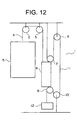
- Fig. 12 is a diagram schematically showing the construction of a conventional elevator device similar, for example, to the one disclosed in EP0731052A1.
- a hoistway 1 in the upper portion of a hoistway 1, there are arranged first and second rotatable car suspension sheaves 2 and 3.
- a main rope 4 is wrapped around the first and second car suspension sheaves 2 and 3.
- a car 5 and a counterweight 6 are suspended in the hoistway 1 by the main rope 4.
- a 1:1 roping is adopted as the rope arrangement for the main rope 4.
- an upper counterweight sheave 7 which is rotatable.
- a lower counterweight sheave 8 which is rotatable.
- an upper hoistway sheave 9 Arranged in the upper portion of the hoistway 1 is an upper hoistway sheave 9 that is rotatable.
- a lower hoistway sheave 10 Arranged in the lower portion of the hoistway 1 is a lower hoistway sheave 10 that is rotatable.
- a drive rope 11 is wrapped around the upper counterweight sheave 7, the upper hoistway sheave 9, the lower hoistway sheave 10, and the lower counterweight sheave 8.
- one end portion (the upper end portion) of the drive rope 11 is connected to the top portion of the hoistway 1.
- a tension weight 12 Suspended from the other end portion (the lower end portion) of the drive rope 11 is a tension weight 12 for imparting tension to the drive rope 11.
- a 2:1 roping is adopted as the rope arrangement for the drive rope 11.
- a driving machine (not shown) for causing the counterweight 6 to ascend and descend through the drive rope 11.
- the lower hoistway sheave 10 is rotated by the driving machine, whereby the counterweight 6 is caused to ascend and descend through the drive rope 11. Due to this arrangement, the car 5 connected to the counterweight 6 through the main rope 4 ascends and descends in the hoistway 1 along a guide rail (not shown).
- the upper counterweight sheave 7 is arranged on top of the counterweight 6, and the lower counterweight sheave 8 is arranged underneath the counterweight 6, so that the dimension of the counterweight 6 in the height direction becomes large, with the result that the dimension of the hoistway 1 in the height direction is increased.
- This problem becomes conspicuous, in particular, when an emergency stop device is mounted on the counterweight 6.
- This invention has been made with a view toward solving the above problem in the prior art. Therefore it is an object of this invention to provide an elevator device capable of restraining an increase in the dimension of the counterweight in the height direction and of effectively utilizing the space inside the building.
- an elevator device comprising: a hoistway; a rotatable car suspension sheave arranged in the upper portion of the hoistway; a main rope wrapped around the car suspension sheave; a car and a counterweight suspended in the hoistway by the main rope; a plurality of rotatable counterweight sheaves mounted on the counterweight; a plurality of rotatable hoistway sheaves arranged in the upper portion and the lower portion of the hoistway; a drive rope wrapped around the counterweight sheaves and the hoistway sheaves; and a driving machine which causes the counterweight to ascend and descend through the drive rope by rotating at least one of the counterweight sheaves and the hoistway sheaves, wherein all the counterweight sheaves are arranged on one of the upper portion and the lower portion of the counterweight.
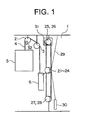
- Fig. 1 is a schematic diagram showing the construction of an elevator device according to Embodiment 1 of this invention.
- first and second rotatable car suspension sheaves are arranged in the upper portion of a hoistway 1.
- a main rope 4 is wrapped around the first and second car suspension sheaves 2 and 3.
- a car 5 and a counterweight 6 are suspended in the hoistway 1 by the main rope 4.
- a 1:1 roping is adopted as the rope arrangement for the main rope 4.
- First through fourth counterweight sheaves 21 through 24 are mounted above the counterweight 6.
- the first through fourth counterweight sheaves 21 through 24 are arranged coaxially and are independently rotatable.
- first and second upper hoistway sheaves 25 and 26 In the upper portion of the hoistway 1, there are arranged first and second upper hoistway sheaves 25 and 26.
- the first and second upper hoistway sheaves 25 and 26 are arranged coaxially and are independently rotatable.
- first and second lower hoistway sheaves 27 and 28 In the lower portion of the hoistway 1, there are arranged first and second lower hoistway sheaves 27 and 28.
- the first and second lower hoistway sheaves 27 and 28 are arranged coaxially and are independently rotatable.
- a drive rope 29 is wrapped around the first through fourth counterweight sheaves 21 through 24, the first and second upper hoistway sheaves 25 and 26, and the first and second lower hoistway sheaves 27 and 28.
- One end portion (the upper end portion) of the drive rope 29 is connected to the top portion of the hoistway 1.
- a tension weight 30 for imparting tension to the drive rope 29.
- a 4:1 roping is adopted as the rope arrangement for the drive rope 29.
- first upper hoistway sheave 25 Connected to the first upper hoistway sheave 25 is the rotation shaft of a driving machine 31 for causing the counterweight 6 to ascend and descend through the drive rope 29. That is, the first upper hoistway sheave 25 also serves as the drive sheave of the driving machine 31. Further, the first car suspension sheave 2 is provided with a brake device 32.
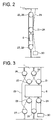
- Fig. 2 is an explanatory diagram illustrating the rope arrangement of the drive rope 29 of Fig. 1, and Fig. 3 is a development of Fig. 2.
- the drive rope 29 is wrapped around the sheaves in the following order: the first counterweight sheave 21, the first upper hoistway sheave 25, the second counterweight sheave 22, the second upper hoistway sheave 26, the first lower hoistway sheave 27, the third counterweight sheave 23, the second lower hoistway sheave 28, and the fourth counterweight sheave 24.
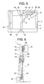
- Fig. 4 is a side view showing an example of a specific layout of the elevator device of Fig. 1
- Fig. 5 is a plan view showing the elevator device of Fig. 4
- Fig. 4 is a side view as seen from the direction of an arrow V of Fig. 5.
- Fig. 6 is a side view showing the positional relationship of the counterweight sheaves 21 through 24 and the hoistway sheaves 25 through 28.
- the counterweight sheaves 21 through 24 and the hoistway sheaves 25 through 28 are arranged such that, in plan view, their rotation centers cross the center line 6c of the counterweight 6 obliquely. Further, in order to lessen the overlap of the car 5 and the driving machine 31 in plan view, a thin type hoist having a small axial dimension is used as the driving machine 31.
- all the counterweight sheaves 21 through 24 and all the hoistway sheaves 25 through 28 are arranged such that their rotation shafts are superimposed one upon the other in plan view. That is, the upper hoistway sheaves 25 and 26 are arranged directly above the counterweight sheaves 21 through 24, and the lower hoistway sheaves 27 and 28 are arranged directly below the counterweight sheaves 21 through 24.
- Fig. 5 there are provided in the hoistway 1 car guide rails 33 for guiding the ascent/descent of the car 5 and a counterweight guide rail 34 for guiding the ascent/descent of the counterweight 6.
- the guide rails 33 and 34 are fixed in the hoistway 1 by a plurality of rail brackets 35.
- each hoistway floor there is provided a hoistway door 36.
- the car 5 is provided with a car door 37 opposed to the hoistway door 36.
- all the counterweight sheaves 21 through 24 are arranged above the counterweight 6, so that it is possible to restrain an increase in the dimension of the counterweight 6 in the height direction, making it possible to diminish the height dimension of the hoistway 1, whereby it is possible to effectively utilize the space in the building.
- first through fourth counterweight sheaves 21 through 24 are arranged coaxially, it is possible to simplify the construction and reduce the number of parts.
- first and second upper hoistway sheaves 25 and 26 are arranged coaxially, and the first and second lower hoistway sheaves 27 and 28 are arranged coaxially, it is possible to further simplify the construction and reduce the number of parts.
- the first car suspension sheave 2 is provided with the brake device 32, if the drive rope 29 should break, it is possible to prevent the car 5 from falling. Thus, it is possible to provide only one drive rope 29.
- Fig. 7 is a plan view of an elevator device according to Embodiment 2 of this invention.
- the counterweight sheaves 21 through 24 and the hoistway sheaves 25 through 28 are arranged such that, in plan view, their rotation shafts extend parallel to the center line 6c of the counterweight 6.
- a vertical type hoist having a large axial dimension is used as a driving machine 38. otherwise, this embodiment is of the same construction as Embodiment 1.
- Fig. 8 is an explanatory diagram illustrating the rope arrangement of the drive rope of an elevator device according to Embodiment 3 of this invention
- Fig. 9 is a development of Fig. 8.
- Embodiment 3 a 2:1 roping is adopted as the rope arrangement for the drive rope.
- first and second counterweight sheaves 41 and 42 are mounted on top of the counterweight 6.
- the first and second counterweight sheaves 41 and 42 are arranged coaxially and are independently rotatable.
- a rotatable upper hoistway sheave 43 In the upper portion of the hoistway 1, there is arranged a rotatable lower hoistway sheave 44.
- the drive rope 29 is wrapped around the first and second counterweight sheaves 41 and 42, the upper hoistway sheave 43, and the lower hoistway sheave 44.
- One end portion (the upper end portion) of the drive rope 29 is connected to the top portion of the hoistway 1.
- a tension weight 30 imparting tension to the drive rope 29 is suspended from the other end portion (the lower end portion) of the drive rope 29.
- the drive rope 29 is successively wrapped in the following order: the first counterweight sheave 41, the upper hoistway sheave 43, the lower hoistway sheave 44, and the second counterweight sheave 42.
- the first and second counterweight sheaves 41 and 42 are rotated in the same direction as each other.
- the rotating speeds of the first and second counterweight sheaves 41 and 42 may slightly differ according to the expansion of the drive rope 29.
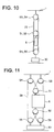
- Fig. 10 is an explanatory diagram illustrating the rope arrangement of the drive rope of an elevator device according to Embodiment 4 of this invention
- Fig. 11 is a development of Fig. 10.
- This Embodiment 4 adopts a 3:1 roping as the rope arrangement for the drive rope.
- first and second counterweight sheaves 51 and 52 are mounted on top of the counterweight 6.
- the first and second counterweight sheaves 51 and 52 are arranged coaxially, and are independently rotatable.
- first and second upper hoistway sheaves 53 and 54 In the upper portion of the hoistway 1, there are arranged first and second upper hoistway sheaves 53 and 54.
- the first and second upper hoistway sheaves 53 and 54 are arranged coaxially, and are independently rotatable.
- first and second lower hoistway sheaves 55 and 56 In the lower portion of the hoistway 1, there are arranged first and second lower hoistway sheaves 55 and 56.
- the first and second lower hoistway sheaves 55 and 56 are arranged coaxially, and are independently rotatable.
- the drive rope 29 is wrapped around the first and second counterweight sheaves 51 and 52, the first and second upper hoistway sheaves 53 and 54, and the first and second lower hoistway sheaves 55 and 56. Both end portions of the drive rope 29 are connected to the counterweight 6. A tension weight 30 imparting tension to the drive rope 29 is suspended from the first and second lower hoistway sheaves 55 and 56.
- the drive rope 29 is successively wrapped around the sheaves in the following order: the first upper hoistway sheave 53, the first counterweight sheave 51, the second upper hoistway sheave 54, the first lower hoistway sheave 55, the second counterweight sheave 52, and the second lower hoistway sheave 56.
- the driving machine is connected to the upper hoistway sheaves, it is also possible to connect the driving machine to other sheaves around which the drive rope is wrapped. That is, it is also possible to use other sheaves as the drive sheaves.
- the driving machine may also be mounted in the lower portion of the hoistway or on the counterweight.
- the counterweight sheaves are mounted only on top of the counterweight, it is also possible to mount them only on the lower side thereof.
- counterweight sheaves are arranged coaxially, it is also possible to arrange a plurality of counterweight sheaves side by side on the upper or lower side of the counterweight, thereby restraining an increase in the height dimension of the counterweight.
- a synthetic fiber rope consisting of a synthetic fiber such as an aramid fiber.
- a synthetic fiber rope has a high friction coefficient and is superior in flexibility. Thus, it makes it possible to reduce the sheave diameter and achieve an overall reduction in size.
- the rope arrangement of the drive rope is not restricted to those of the above examples; it is possible to employ an arbitrary N:1 roping (where N is a natural number not less than 2). That is, by making N large while restraining an increase in the height dimension of the counterweight, it is possible for the driving machine to be a small and inexpensive one, making it possible to effectively utilize the space in the building.
- the number of counterweight sheaves is N when N is an even number, and N-1 when N is an odd number.
- the number of upper hoistway sheaves is N/2 when N is an even number and N-1 when N is an odd number.
- the number of lower hoistway sheaves is N/2 when N is an even number, and N-1 when N is an odd number.
Landscapes
- Engineering & Computer Science (AREA)
- Civil Engineering (AREA)
- Mechanical Engineering (AREA)
- Structural Engineering (AREA)
- Lift-Guide Devices, And Elevator Ropes And Cables (AREA)
- Cage And Drive Apparatuses For Elevators (AREA)
Abstract
Description
For this purpose, it is desirable to provide a brake device on the main rope side as shown in Embodiment 1.
Claims (9)
- An elevator device comprising:characterized in thata hoistway (1);a rotatable car suspension sheave (2) arranged in the upper portion of the hoistway (1);a main rope (4) wrapped around the car suspension sheave (2);a car (5) and a counterweight (6) suspended in the hoistway (1) by the main rope (4);a plurality of rotatable counterweight sheaves (21-24, 41, 42, 51, 52) mounted on the counterweight (6);a plurality of rotatable hoistway sheaves (25-28, 53-56) arranged in the upper portion and the lower portion of the hoistway (1);a drive rope (29) wrapped around the counterweight sheaves (21-24, 41, 42, 51, 52) and the hoistway sheaves (25-28, 53-56); anda driving machine (31, 38) which causes the counterweight (6) to ascend and descend through the drive rope (29) by rotating at least one of the counterweight sheaves (21-24, 41, 42, 51, 52) and the hoistway sheaves (25-28, 53-56),
all the counterweight sheaves (21-24, 41, 42, 51, 52) are arranged on one of the upper portion and the lower portion of the counterweight (6). - An elevator device according to claim 1, wherein all the counterweight sheaves (21-24, 41, 42, 51, 52) are arranged coaxially.
- An elevator device according to claim 1 or 2, wherein the drive rope (29) is arranged in an N:1 roping (N is a natural number not less than 2), and wherein the number of counterweight sheaves (21-24, 41, 42, 51, 52) is N when N is an even number, and N-1 when N is an odd number.
- An elevator device according to any one of claims 1 to 3, wherein a plurality of hoistway sheaves (25-28, 53-56) are arranged coaxially in at least one of the upper portion and the lower portion of the hoistway (1).
- An elevator device according to any one of claims 1 to 4, wherein the rotation shafts of all the counterweight sheaves (21-24, 41, 42, 51, 52) and the rotation shafts of all the hoistway sheaves (25-28, 53-56) are arranged such that, in plan view, they are superimposed one upon the other.
- An elevator device according to any one of claims 1 to 5, wherein the driving machine (31, 38) is arranged in one of the upper portion and the lower portion of the hoistway (1), and wherein the rotation shaft of the driving machine (31, 38) is connected to one of the hoistway sheaves (25-28, 53-56).
- An elevator device according to any one of claims 1 to 6, wherein the drive rope (29) is a flat rope with a flat sectional configuration.
- An elevator device according to any one of claims 1 to 7, wherein the drive rope (29) is a synthetic fiber rope.
- An elevator device according to any one of claims 1 to 8, wherein the car suspension sheave (2) is provided with a brake device (32).
Applications Claiming Priority (1)
| Application Number | Priority Date | Filing Date | Title |
|---|---|---|---|
| PCT/JP2001/004374 WO2002094701A1 (en) | 2001-05-24 | 2001-05-24 | Elevator apparatus |
Publications (3)
| Publication Number | Publication Date |
|---|---|
| EP1396456A1 true EP1396456A1 (en) | 2004-03-10 |
| EP1396456A4 EP1396456A4 (en) | 2004-10-27 |
| EP1396456B1 EP1396456B1 (en) | 2008-01-09 |
Family
ID=11737345
Family Applications (1)
| Application Number | Title | Priority Date | Filing Date |
|---|---|---|---|
| EP01932256A Expired - Lifetime EP1396456B1 (en) | 2001-05-24 | 2001-05-24 | Elevator apparatus |
Country Status (5)
| Country | Link |
|---|---|
| EP (1) | EP1396456B1 (en) |
| JP (1) | JPWO2002094701A1 (en) |
| CN (1) | CN1270957C (en) |
| DE (1) | DE60132372T2 (en) |
| WO (1) | WO2002094701A1 (en) |
Cited By (3)
| Publication number | Priority date | Publication date | Assignee | Title |
|---|---|---|---|---|
| CN102229397A (en) * | 2011-06-09 | 2011-11-02 | 上海微频莱机电科技有限公司 | Lifting device of tower cylinder lifter |
| EP2492232A1 (en) * | 2011-02-24 | 2012-08-29 | Inventio AG | Tensioning device in a lift assembly |
| EP3401265A3 (en) * | 2017-05-12 | 2019-05-01 | Otis Elevator Company | A rope climbing elevator system |
Families Citing this family (5)
| Publication number | Priority date | Publication date | Assignee | Title |
|---|---|---|---|---|
| CN100333991C (en) * | 2003-02-13 | 2007-08-29 | 三菱电机株式会社 | Elevator device |
| EP2390221A1 (en) * | 2003-02-19 | 2011-11-30 | Mitsubishi Denki Kabushiki Kaisha | Elevator |
| KR100975689B1 (en) | 2006-06-01 | 2010-08-12 | 미쓰비시덴키 가부시키가이샤 | Elevator device |
| CN1970422A (en) * | 2006-12-05 | 2007-05-30 | 孟繁贵 | Indirect-drive towed elevator |
| EP3288887A4 (en) * | 2015-04-27 | 2019-03-13 | KONE Corporation | Arrangement for adjusting the tautness of a traction member of an elevator |
Family Cites Families (6)
| Publication number | Priority date | Publication date | Assignee | Title |
|---|---|---|---|---|
| DE19507628A1 (en) * | 1995-03-04 | 1996-09-05 | Dover Europ Aufzuege Gmbh | Elevator |
| FI99264C (en) * | 1995-09-21 | 1998-02-10 | Kone Oy | Drive disk elevator without engine room |
| JP3225811B2 (en) * | 1995-11-06 | 2001-11-05 | 三菱電機株式会社 | Elevator equipment |
| JP2000063057A (en) * | 1998-06-08 | 2000-02-29 | Meidensha Corp | Elevator |
| JP2000247560A (en) * | 1999-02-26 | 2000-09-12 | Mitsubishi Electric Corp | Elevator equipment |
| FI4928U1 (en) * | 2001-01-25 | 2001-05-23 | Kone Corp | Elevator |
-
2001
- 2001-05-24 DE DE60132372T patent/DE60132372T2/en not_active Expired - Lifetime
- 2001-05-24 JP JP2002580696A patent/JPWO2002094701A1/en active Pending
- 2001-05-24 WO PCT/JP2001/004374 patent/WO2002094701A1/en not_active Ceased
- 2001-05-24 EP EP01932256A patent/EP1396456B1/en not_active Expired - Lifetime
- 2001-05-24 CN CN 01812049 patent/CN1270957C/en not_active Expired - Fee Related
Cited By (3)
| Publication number | Priority date | Publication date | Assignee | Title |
|---|---|---|---|---|
| EP2492232A1 (en) * | 2011-02-24 | 2012-08-29 | Inventio AG | Tensioning device in a lift assembly |
| CN102229397A (en) * | 2011-06-09 | 2011-11-02 | 上海微频莱机电科技有限公司 | Lifting device of tower cylinder lifter |
| EP3401265A3 (en) * | 2017-05-12 | 2019-05-01 | Otis Elevator Company | A rope climbing elevator system |
Also Published As
| Publication number | Publication date |
|---|---|
| CN1270957C (en) | 2006-08-23 |
| EP1396456A4 (en) | 2004-10-27 |
| JPWO2002094701A1 (en) | 2004-09-09 |
| DE60132372T2 (en) | 2008-12-24 |
| WO2002094701A1 (en) | 2002-11-28 |
| EP1396456B1 (en) | 2008-01-09 |
| DE60132372D1 (en) | 2008-02-21 |
| CN1440363A (en) | 2003-09-03 |
Similar Documents
| Publication | Publication Date | Title |
|---|---|---|
| CN1329273C (en) | Elevator system with overhead drive motor | |
| US5906251A (en) | Traction sheave elevator | |
| EP0749931B1 (en) | Traction sheave elevator | |
| JP4786121B2 (en) | Elevator equipment | |
| CN1329274C (en) | Machine-roomless elevator system with elevator machine mounted on elevator car | |
| CN1882492B (en) | Elevator pulley | |
| EP1319627B1 (en) | Elevator device | |
| US7156209B2 (en) | Elevator roping arrangement | |
| EP1481935A1 (en) | Elevaltor apparatus | |
| EP1396456A1 (en) | Elevator apparatus | |
| EP1685057B1 (en) | Elevator pulley arrangement | |
| JPH11157762A (en) | Elevator | |
| JP2002145556A (en) | Elevator equipment | |
| JP2002326778A (en) | Elevator and multi-story parking facilities | |
| EP1535875B1 (en) | Elevator device | |
| WO2004046009A1 (en) | Elevator equipment | |
| JPH03177288A (en) | Traction type elevator device | |
| EP1312573A1 (en) | Elevator device | |
| JPWO2002016247A1 (en) | elevator equipment | |
| JP4558336B2 (en) | Elevator drive device | |
| JP4172451B2 (en) | Elevator equipment | |
| JP4443546B2 (en) | Elevator equipment | |
| JPWO2004028948A1 (en) | Elevator equipment | |
| JPWO2004101419A1 (en) | Elevator equipment | |
| EP1602611B1 (en) | Elevator apparatus |
Legal Events
| Date | Code | Title | Description |
|---|---|---|---|
| PUAI | Public reference made under article 153(3) epc to a published international application that has entered the european phase |
Free format text: ORIGINAL CODE: 0009012 |
|
| 17P | Request for examination filed |
Effective date: 20021218 |
|
| AK | Designated contracting states |
Kind code of ref document: A1 Designated state(s): AT BE CH CY DE DK ES FI FR GB GR IE IT LI LU MC NL PT SE TR |
|
| A4 | Supplementary search report drawn up and despatched |
Effective date: 20040913 |
|
| RIC1 | Information provided on ipc code assigned before grant |
Ipc: 7B 66B 11/08 A |
|
| 17Q | First examination report despatched |
Effective date: 20041109 |
|
| RAP1 | Party data changed (applicant data changed or rights of an application transferred) |
Owner name: MITSUBISHI DENKI KABUSHIKI KAISHA |
|
| GRAP | Despatch of communication of intention to grant a patent |
Free format text: ORIGINAL CODE: EPIDOSNIGR1 |
|
| RBV | Designated contracting states (corrected) |
Designated state(s): DE FI FR GB NL |
|
| GRAS | Grant fee paid |
Free format text: ORIGINAL CODE: EPIDOSNIGR3 |
|
| GRAA | (expected) grant |
Free format text: ORIGINAL CODE: 0009210 |
|
| AK | Designated contracting states |
Kind code of ref document: B1 Designated state(s): DE FI FR GB NL |
|
| RAP1 | Party data changed (applicant data changed or rights of an application transferred) |
Owner name: MITSUBISHI DENKI KABUSHIKI KAISHA |
|
| REG | Reference to a national code |
Ref country code: GB Ref legal event code: FG4D |
|
| RAP2 | Party data changed (patent owner data changed or rights of a patent transferred) |
Owner name: MITSUBISHI DENKI KABUSHIKI KAISHA |
|
| RIN2 | Information on inventor provided after grant (corrected) |
Inventor name: NOMURA, MASAMIMITSUBISHI DENKI KABUSHIKI KAISHA |
|
| REF | Corresponds to: |
Ref document number: 60132372 Country of ref document: DE Date of ref document: 20080221 Kind code of ref document: P |
|
| NLT2 | Nl: modifications (of names), taken from the european patent patent bulletin |
Owner name: MITSUBISHI DENKI KABUSHIKI KAISHA Effective date: 20080206 |
|
| ET | Fr: translation filed | ||
| PLBE | No opposition filed within time limit |
Free format text: ORIGINAL CODE: 0009261 |
|
| STAA | Information on the status of an ep patent application or granted ep patent |
Free format text: STATUS: NO OPPOSITION FILED WITHIN TIME LIMIT |
|
| 26N | No opposition filed |
Effective date: 20081010 |
|
| PGFP | Annual fee paid to national office [announced via postgrant information from national office to epo] |
Ref country code: GB Payment date: 20100329 Year of fee payment: 10 |
|
| REG | Reference to a national code |
Ref country code: GB Ref legal event code: 746 Effective date: 20100615 |
|
| PGFP | Annual fee paid to national office [announced via postgrant information from national office to epo] |
Ref country code: FR Payment date: 20100525 Year of fee payment: 10 Ref country code: FI Payment date: 20100512 Year of fee payment: 10 |
|
| PGFP | Annual fee paid to national office [announced via postgrant information from national office to epo] |
Ref country code: NL Payment date: 20100518 Year of fee payment: 10 |
|
| REG | Reference to a national code |
Ref country code: NL Ref legal event code: V1 Effective date: 20111201 |
|
| GBPC | Gb: european patent ceased through non-payment of renewal fee |
Effective date: 20110524 |
|
| PG25 | Lapsed in a contracting state [announced via postgrant information from national office to epo] |
Ref country code: FI Free format text: LAPSE BECAUSE OF NON-PAYMENT OF DUE FEES Effective date: 20110524 Ref country code: NL Free format text: LAPSE BECAUSE OF NON-PAYMENT OF DUE FEES Effective date: 20111201 |
|
| REG | Reference to a national code |
Ref country code: FR Ref legal event code: ST Effective date: 20120131 |
|
| PG25 | Lapsed in a contracting state [announced via postgrant information from national office to epo] |
Ref country code: FR Free format text: LAPSE BECAUSE OF NON-PAYMENT OF DUE FEES Effective date: 20110531 |
|
| PG25 | Lapsed in a contracting state [announced via postgrant information from national office to epo] |
Ref country code: GB Free format text: LAPSE BECAUSE OF NON-PAYMENT OF DUE FEES Effective date: 20110524 |
|
| PGFP | Annual fee paid to national office [announced via postgrant information from national office to epo] |
Ref country code: DE Payment date: 20130522 Year of fee payment: 13 |
|
| REG | Reference to a national code |
Ref country code: DE Ref legal event code: R119 Ref document number: 60132372 Country of ref document: DE |
|
| REG | Reference to a national code |
Ref country code: DE Ref legal event code: R119 Ref document number: 60132372 Country of ref document: DE Effective date: 20141202 |
|
| PG25 | Lapsed in a contracting state [announced via postgrant information from national office to epo] |
Ref country code: DE Free format text: LAPSE BECAUSE OF NON-PAYMENT OF DUE FEES Effective date: 20141202 |