EP1396331A1 - Cord-like seal for vehicle, process and apparatus for manufacturing it - Google Patents
Cord-like seal for vehicle, process and apparatus for manufacturing it Download PDFInfo
- Publication number
- EP1396331A1 EP1396331A1 EP03019835A EP03019835A EP1396331A1 EP 1396331 A1 EP1396331 A1 EP 1396331A1 EP 03019835 A EP03019835 A EP 03019835A EP 03019835 A EP03019835 A EP 03019835A EP 1396331 A1 EP1396331 A1 EP 1396331A1
- Authority
- EP
- European Patent Office
- Prior art keywords
- strand
- metallic
- sections
- soft
- reinforcement
- Prior art date
- Legal status (The legal status is an assumption and is not a legal conclusion. Google has not performed a legal analysis and makes no representation as to the accuracy of the status listed.)
- Granted
Links
Images

Classifications
-
- F—MECHANICAL ENGINEERING; LIGHTING; HEATING; WEAPONS; BLASTING
- F16—ENGINEERING ELEMENTS AND UNITS; GENERAL MEASURES FOR PRODUCING AND MAINTAINING EFFECTIVE FUNCTIONING OF MACHINES OR INSTALLATIONS; THERMAL INSULATION IN GENERAL
- F16J—PISTONS; CYLINDERS; SEALINGS
- F16J15/00—Sealings
- F16J15/02—Sealings between relatively-stationary surfaces
- F16J15/06—Sealings between relatively-stationary surfaces with solid packing compressed between sealing surfaces
- F16J15/061—Sealings between relatively-stationary surfaces with solid packing compressed between sealing surfaces with positioning means
-
- B—PERFORMING OPERATIONS; TRANSPORTING
- B29—WORKING OF PLASTICS; WORKING OF SUBSTANCES IN A PLASTIC STATE IN GENERAL
- B29C—SHAPING OR JOINING OF PLASTICS; SHAPING OF MATERIAL IN A PLASTIC STATE, NOT OTHERWISE PROVIDED FOR; AFTER-TREATMENT OF THE SHAPED PRODUCTS, e.g. REPAIRING
- B29C48/00—Extrusion moulding, i.e. expressing the moulding material through a die or nozzle which imparts the desired form; Apparatus therefor
- B29C48/16—Articles comprising two or more components, e.g. co-extruded layers
- B29C48/18—Articles comprising two or more components, e.g. co-extruded layers the components being layers
- B29C48/19—Articles comprising two or more components, e.g. co-extruded layers the components being layers the layers being joined at their edges
-
- B—PERFORMING OPERATIONS; TRANSPORTING
- B29—WORKING OF PLASTICS; WORKING OF SUBSTANCES IN A PLASTIC STATE IN GENERAL
- B29C—SHAPING OR JOINING OF PLASTICS; SHAPING OF MATERIAL IN A PLASTIC STATE, NOT OTHERWISE PROVIDED FOR; AFTER-TREATMENT OF THE SHAPED PRODUCTS, e.g. REPAIRING
- B29C48/00—Extrusion moulding, i.e. expressing the moulding material through a die or nozzle which imparts the desired form; Apparatus therefor
- B29C48/25—Component parts, details or accessories; Auxiliary operations
- B29C48/36—Means for plasticising or homogenising the moulding material or forcing it through the nozzle or die
- B29C48/365—Means for plasticising or homogenising the moulding material or forcing it through the nozzle or die using pumps, e.g. piston pumps
- B29C48/37—Gear pumps
-
- B—PERFORMING OPERATIONS; TRANSPORTING
- B29—WORKING OF PLASTICS; WORKING OF SUBSTANCES IN A PLASTIC STATE IN GENERAL
- B29C—SHAPING OR JOINING OF PLASTICS; SHAPING OF MATERIAL IN A PLASTIC STATE, NOT OTHERWISE PROVIDED FOR; AFTER-TREATMENT OF THE SHAPED PRODUCTS, e.g. REPAIRING
- B29C48/00—Extrusion moulding, i.e. expressing the moulding material through a die or nozzle which imparts the desired form; Apparatus therefor
- B29C48/25—Component parts, details or accessories; Auxiliary operations
- B29C48/36—Means for plasticising or homogenising the moulding material or forcing it through the nozzle or die
- B29C48/375—Plasticisers, homogenisers or feeders comprising two or more stages
- B29C48/387—Plasticisers, homogenisers or feeders comprising two or more stages using a screw extruder and a gear pump
-
- B—PERFORMING OPERATIONS; TRANSPORTING
- B29—WORKING OF PLASTICS; WORKING OF SUBSTANCES IN A PLASTIC STATE IN GENERAL
- B29C—SHAPING OR JOINING OF PLASTICS; SHAPING OF MATERIAL IN A PLASTIC STATE, NOT OTHERWISE PROVIDED FOR; AFTER-TREATMENT OF THE SHAPED PRODUCTS, e.g. REPAIRING
- B29C48/00—Extrusion moulding, i.e. expressing the moulding material through a die or nozzle which imparts the desired form; Apparatus therefor
- B29C48/25—Component parts, details or accessories; Auxiliary operations
- B29C48/36—Means for plasticising or homogenising the moulding material or forcing it through the nozzle or die
- B29C48/49—Means for plasticising or homogenising the moulding material or forcing it through the nozzle or die using two or more extruders to feed one die or nozzle
-
- B—PERFORMING OPERATIONS; TRANSPORTING
- B60—VEHICLES IN GENERAL
- B60J—WINDOWS, WINDSCREENS, NON-FIXED ROOFS, DOORS, OR SIMILAR DEVICES FOR VEHICLES; REMOVABLE EXTERNAL PROTECTIVE COVERINGS SPECIALLY ADAPTED FOR VEHICLES
- B60J10/00—Sealing arrangements
- B60J10/15—Sealing arrangements characterised by the material
- B60J10/16—Sealing arrangements characterised by the material consisting of two or more plastic materials having different physical or chemical properties
-
- B—PERFORMING OPERATIONS; TRANSPORTING
- B60—VEHICLES IN GENERAL
- B60J—WINDOWS, WINDSCREENS, NON-FIXED ROOFS, DOORS, OR SIMILAR DEVICES FOR VEHICLES; REMOVABLE EXTERNAL PROTECTIVE COVERINGS SPECIALLY ADAPTED FOR VEHICLES
- B60J10/00—Sealing arrangements
- B60J10/15—Sealing arrangements characterised by the material
- B60J10/18—Sealing arrangements characterised by the material provided with reinforcements or inserts
-
- B—PERFORMING OPERATIONS; TRANSPORTING
- B60—VEHICLES IN GENERAL
- B60J—WINDOWS, WINDSCREENS, NON-FIXED ROOFS, DOORS, OR SIMILAR DEVICES FOR VEHICLES; REMOVABLE EXTERNAL PROTECTIVE COVERINGS SPECIALLY ADAPTED FOR VEHICLES
- B60J10/00—Sealing arrangements
- B60J10/30—Sealing arrangements characterised by the fastening means
- B60J10/32—Sealing arrangements characterised by the fastening means using integral U-shaped retainers
-
- B—PERFORMING OPERATIONS; TRANSPORTING
- B60—VEHICLES IN GENERAL
- B60J—WINDOWS, WINDSCREENS, NON-FIXED ROOFS, DOORS, OR SIMILAR DEVICES FOR VEHICLES; REMOVABLE EXTERNAL PROTECTIVE COVERINGS SPECIALLY ADAPTED FOR VEHICLES
- B60J10/00—Sealing arrangements
- B60J10/80—Sealing arrangements specially adapted for opening panels, e.g. doors
-
- B—PERFORMING OPERATIONS; TRANSPORTING
- B29—WORKING OF PLASTICS; WORKING OF SUBSTANCES IN A PLASTIC STATE IN GENERAL
- B29C—SHAPING OR JOINING OF PLASTICS; SHAPING OF MATERIAL IN A PLASTIC STATE, NOT OTHERWISE PROVIDED FOR; AFTER-TREATMENT OF THE SHAPED PRODUCTS, e.g. REPAIRING
- B29C48/00—Extrusion moulding, i.e. expressing the moulding material through a die or nozzle which imparts the desired form; Apparatus therefor
- B29C48/001—Combinations of extrusion moulding with other shaping operations
- B29C48/0022—Combinations of extrusion moulding with other shaping operations combined with cutting
-
- B—PERFORMING OPERATIONS; TRANSPORTING
- B29—WORKING OF PLASTICS; WORKING OF SUBSTANCES IN A PLASTIC STATE IN GENERAL
- B29C—SHAPING OR JOINING OF PLASTICS; SHAPING OF MATERIAL IN A PLASTIC STATE, NOT OTHERWISE PROVIDED FOR; AFTER-TREATMENT OF THE SHAPED PRODUCTS, e.g. REPAIRING
- B29C48/00—Extrusion moulding, i.e. expressing the moulding material through a die or nozzle which imparts the desired form; Apparatus therefor
- B29C48/03—Extrusion moulding, i.e. expressing the moulding material through a die or nozzle which imparts the desired form; Apparatus therefor characterised by the shape of the extruded material at extrusion
- B29C48/12—Articles with an irregular circumference when viewed in cross-section, e.g. window profiles
-
- B—PERFORMING OPERATIONS; TRANSPORTING
- B29—WORKING OF PLASTICS; WORKING OF SUBSTANCES IN A PLASTIC STATE IN GENERAL
- B29C—SHAPING OR JOINING OF PLASTICS; SHAPING OF MATERIAL IN A PLASTIC STATE, NOT OTHERWISE PROVIDED FOR; AFTER-TREATMENT OF THE SHAPED PRODUCTS, e.g. REPAIRING
- B29C48/00—Extrusion moulding, i.e. expressing the moulding material through a die or nozzle which imparts the desired form; Apparatus therefor
- B29C48/15—Extrusion moulding, i.e. expressing the moulding material through a die or nozzle which imparts the desired form; Apparatus therefor incorporating preformed parts or layers, e.g. extrusion moulding around inserts
-
- B—PERFORMING OPERATIONS; TRANSPORTING
- B29—WORKING OF PLASTICS; WORKING OF SUBSTANCES IN A PLASTIC STATE IN GENERAL
- B29L—INDEXING SCHEME ASSOCIATED WITH SUBCLASS B29C, RELATING TO PARTICULAR ARTICLES
- B29L2031/00—Other particular articles
- B29L2031/26—Sealing devices, e.g. packaging for pistons or pipe joints
Definitions
- the invention relates to a strand-shaped vehicle seal, the with a flexible reinforcement with U or C-shaped or from it derivable cross section is equipped, as well as procedures and devices for their manufacture.
- Seals needed to prevent water, exhaust gases, Prevent dust and / or drafts in the vehicle interior.
- This Seals consist of sealing strips between each Parts that are manufactured endlessly and for installation on the required lengths can be cut.
- these sealing strips are usually included a metallic reinforcement in the form of inserted wires (EP 11 53 799) or from punched, unwound from a roll and sheet metal strips bent into the required shape as reinforcement and a jacket made of an extruded elastic mass manufactured.
- GB 23 27 699 A shows a strand-like one Vehicle seal, consisting of a single extrudate, which at least at the curved corners a prefabricated, preferably made of metal in the form of stamped sheet metal Reinforcement coated.
- the invention avoids the disadvantages of the prior art. It is the object of the invention to use simple means to make it recyclable Seal without creating metallic reinforcement, whose manufacture and processing is easier and which in simply constructed machines can be manufactured.
- the vehicle seal according to the invention with a flexible strand-shaped reinforcement is characterized in that the Reinforcement a strand of at least two different ones Forms substances that consists of individual sections of a non-metallic, soft elastic material together with individual Sections of another non-metallic, but shape and rigid material, the individual sections the reinforcement intermittently alternately one after the other are arranged.
- the U- or C-shaped cross-sectional shape gives the shape and rigid material of reinforcement the possibility of on body parts of the vehicle to be clamped, thereby the attachment of the strip-shaped vehicle seal on Vehicle is made possible.
- a metal-free strand-like vehicle seal get that easier to process, dispose of and is to be recycled.
- the vehicle seals are on a protruding Edge attached, but they can also be inserted into a groove become.
- the sections of the non-metallic, but soft elastic Materials a different or the same length as the sections of the have non-metallic, but dimensionally and flexurally rigid material.
- the non-metallic, but soft-elastic material is thermoplastic elastomer and that the non-metallic, however, rigid and rigid material is a plastic.
- the Reinforcement strand with one or more soft or plastic materials fully or partially encased.
- the other soft or plastic materials can at least completely or partially enclose a cavity.
- the process for producing this strand-like vehicle seal is characterized by the fact that the reinforcement is a strand at least two different substances is formed by one non-metallic, soft-elastic material in individual sections along with another non-metallic, however, rigid and rigid material in individual sections is formed, the individual sections being intermittent, can be arranged alternately one after the other.
- thermoplastic elastomer As non-metallic rigid and rigid material a plastic.
- a device for producing this strand-shaped vehicle seal, with a flexible reinforcement with U- or C-shaped or derivable cross-section is, the reinforcement strand from at least two different Substances that are intermittent as individual sections, are alternately arranged one behind the other, consists of at least two extruders and a common one Spray head and is characterized in that between the two Extruders and the common spray head an transmission device which is the strands of the two extruders divides and the divided extrudate masses in constant change one after the other in the common spray head.
- the transmission device can consist of two rotors, which are recessed in size and between these recesses have projections, the projections one rotor each in the recesses of the other rotor intervene that the geometric shape of the Projections and the recesses is chosen so that the The extent of the projection depends on the circumference of the recess, in which he intervenes, passes it on and in doing so Existing volume between the perimeter of the recess Recess and the extent of the projection is reduced and that a fixed opening leading to the spray head in the housing at the location of the inner circumference of the recess and the Outer periphery of the projection formed chamber for the exit of the extrudate from this is constantly changing in volume changing chamber is provided.
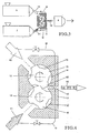
- the sealing strip shown in Fig.1 consists of an intermittent extruded soft elastic mass 1, between the parts of which are U-shaped in cross-section as reinforcement Body 2 are located, which is also extruded from a harder Plastic exist, which are spaced apart between the parts from the soft elastic mass 1 arranged are. These bodies 2 serving as reinforcement have a less elasticity, but greater hardness.
- This seal string is of a further elastic mass 3, which also is applied in the extrusion process, coated. This one more As shown in FIG. 2, plastic compound 3 can have sealing lips 4 wear and enclose a cavity 5.
- This seal string can be in a wide variety of dimensions and cross-sectional shapes can be made, it can be made with different extrudable materials to be completely or partially encased.
- the sealing lips 4 and cavities in the manner of the cavity 5 can, however, also be made in one piece with the elastic mass 1 be produced in the extrusion process.
- FIGS. 1 and 2 show an extrusion system for producing a two extrudable materials of existing sealing strip, in which one material 1 between the other material 2 is arranged intermittently, as shown in FIGS. 1 and 2.
- This System consists of two extruders 6,7 and a common one Spray head 8. It is characterized in that between the two extruders 6, 7 and the spray head 8, a device 9 is arranged which is the strands 10, 11 of the two extruders 6.7 in cuts perpendicular to the strand axis and the divided Extrudate masses in constant change in the presses common spray head 8.
- the geometric shape of the protrusions 15 and recesses 14 is chosen so that the scope of the projection 15 each on the circumference of the recess 14, in which he intervenes, passes on and thereby in this Recess 14 existing volume between the circumference of the Recess 14 and the circumference of the projection 15 is reduced.
- a housing leading to the spray head 8 is located in the housing 17 Channel 18, which at the location of the engagement of the projections 15th and recesses 14 of the rotors 12, 13 begins and to Spray head 8 leads.
- the two rotors 12, 13 work similarly a gear pump: you add the 6.7 from the two extruders extruded materials intermittently together because they one after the other in the recess 14 of the rotar 12 and then that in the recess 14 of the rotor 13 Press out the stored material in a constant sequence and through forward the channel 18 to the spray head 8.
- Bypasses 19 can be provided which cover the path of the bypass extruded materials via the rotors 12, 13.
Abstract
Description
Die Erfindung betrifft eine strangförmige Fahrzeugdichtung, die mit einer flexiblen Bewehrung mit U- oder C-förmigem oder daraus ableitbarem Querschnitt ausgestattet ist, sowie Verfahren und Vorrichtungen zu deren Herstellung.The invention relates to a strand-shaped vehicle seal, the with a flexible reinforcement with U or C-shaped or from it derivable cross section is equipped, as well as procedures and devices for their manufacture.
Beim Zusammenbau der Karosserieteile von Kraft- und anderen Fahrzeugen und an Orten, wo bewegliche Karosserieteile an unbeweglichen Karosserieteilen anliegen, werden an vielen Stellen Dichtungen benötigt, die das Eindringen von Wasser, Abgasen, Staub und/oder Zugluft in Fahrzeuginnenräume verhindern. Diese Dichtungen bestehen aus Dichtungsstreifen zwischen den einzelnen Teilen, die endlos hergestellt und für den Einbau auf die benötigten Längen geschnitten werden.When assembling the body parts of power and others Vehicles and in places where moving body parts on immovable Body parts are in contact in many places Seals needed to prevent water, exhaust gases, Prevent dust and / or drafts in the vehicle interior. This Seals consist of sealing strips between each Parts that are manufactured endlessly and for installation on the required lengths can be cut.
Im Stand der Technik werden diese Dichtungsstreifen meist mit
einer metallischen Bewehrung in Form eingelegter Drähte (EP 11
53 799) oder aus gestanzten, von einer Rolle abgewickelten und
in die benötigte Form gebogenen Blechstreifen als Bewehrung
und einer Ummantelung aus einer extrudierten elastischen Masse
hergestellt. So zeigt die GB 23 27 699 A eine strangförmige
Fahrzeugdichtung, bestehend aus einem einzigen Extrudat, welches
zumindet an den gebogenen Ecken eine vorgefertigte, vorzugsweise
aus Metall in Form von gestanztem Blech hergestellte
Bewehrung ummantelt.In the prior art, these sealing strips are usually included
a metallic reinforcement in the form of inserted wires (
Ein anderes Verfahren der Herstellung besteht im Stand der Technik aus mäanderförmig gebogenen Runddrähten, welche mit textilen Fäden zusammengefügt und welche ebenfalls von einer extrudierten elastischen Masse ummantelt werden. Die Verformung solcher Streifen zu der für ein Dichtungsprofil benötigten U-Form erfolgt kontinuierlich in mehreren Schritten, meist in angetriebenen Rollensystemen.Another method of manufacture is in the prior art Technology made of meandering round wires, which assembled with textile threads and which also from an extruded elastic mass can be encased. The Deformation of such strips to that for a sealing profile required U shape takes place continuously in several steps, mostly in driven roller systems.
Die Herstellung dieser Dichtungsstreifen ist aufwendig und teuer, die Verwendung von Metall als Bewehrung der Elastomermasse ist bei der späteren Verarbeitung und Nutzung der strangförmigen Fahrzeugdichtungen oft nachteilig. Die Entsorgung und ein Recycling ist mit Schwierigkeiten verbunden.The production of these sealing strips is complex and expensive, the use of metal as reinforcement of the elastomer mass is in the later processing and use of the strand-shaped vehicle seals are often disadvantageous. The disposal and recycling is difficult.
Die Erfindung vermeidet die Nachteile des Standes der Technik. Es ist die Aufgabe der Erfindung, mit einfachen Mitteln eine recyclebare Dichtung ohne metallische Festigkeitsträger zu schaffen, deren Fertigung und Verarbeitung einfacher ist und die in einfach aufgebauten Maschinen herstellbar ist.The invention avoids the disadvantages of the prior art. It is the object of the invention to use simple means to make it recyclable Seal without creating metallic reinforcement, whose manufacture and processing is easier and which in simply constructed machines can be manufactured.
Die erfindungsgemäße Fahrzeugdichtung mit einer flexiblen strangförmige Bewehrung zeichnet sich dadurch aus, daß die Bewehrung einen Strang aus wenigstens zwei verschiedenen Stoffen bildet, der aus einzelnen Abschnitten eines nichtmetallischen, weich-elastischen Materials zusammen mit einzelnen Abschnitten eines anderen nichtmetallischen, jedoch form- und biegesteifen Materials besteht, wobei die einzelnen Abschnitte der Bewehrung intermittierend jeweils hintereinander im Wechsel angeordnet sind.The vehicle seal according to the invention with a flexible strand-shaped reinforcement is characterized in that the Reinforcement a strand of at least two different ones Forms substances that consists of individual sections of a non-metallic, soft elastic material together with individual Sections of another non-metallic, but shape and rigid material, the individual sections the reinforcement intermittently alternately one after the other are arranged.
Die aus einem nichtmetallischen, jedoch form- und biegesteifem Material bestehenden Teile der Bewehrung mit U- oder C-förmigem oder daraus ableitbarem Querschnitt bilden die klemmenden Teile der Bewehrung, die zwischen ihnen angeordneten weichen elastischen Abschnitte geben der Bewehrung die Biegsamkeit und beide zusammenhängenden Arten der Abschnitte der Bewehrung sind in das weiche Material der Fahrzeugdichtung ganz oder teilweise eingebettet und bilden mit diesem einen Profilstrang.The one from a non-metallic, but rigid and rigid Material existing parts of the reinforcement with U or C-shaped or the cross-section that can be derived from them form the clamping ones Parts of the reinforcement that give way between them elastic sections give the reinforcement flexibility and both related types of sections of the Reinforcement is in the soft material of the vehicle seal completely or partially embedded and form with this one Extruded profile.
Durch die U- oder C-förmige Querschnittsform erhält das formund biegesteife Material der Bewehrung die Möglichkeit, an Karosserieteilen des Fahrzeugs festgeklemmt zu werden, wodurch die Befestigung der streifenförmigen Fahrzeugdichtung am Fahrzeug ermöglicht wird.The U- or C-shaped cross-sectional shape gives the shape and rigid material of reinforcement the possibility of on body parts of the vehicle to be clamped, thereby the attachment of the strip-shaped vehicle seal on Vehicle is made possible.
Auf diese Weise wird eine metallfreie strangförmige Fahrzeugdichtung erhalten, der leichter zu verarbeiten, zu entsorgen und zu recyclen ist. Die Fahrzeugdichtungen werden auf eine vorstehende Kante aufgesteckt, sie können aber auch in eine Nut eingesetzt werden.In this way, a metal-free strand-like vehicle seal get that easier to process, dispose of and is to be recycled. The vehicle seals are on a protruding Edge attached, but they can also be inserted into a groove become.
Je nach den Anforderungen der Praxis an die Dichtungen, je nach den geraden und den kurvenförmigen Verläufen der in ein Fahrzeug eingebauten Dichtung kann es zweckmäßig sein, daß die Abschnitte des nichtmetallischen, jedoch weichelastischen Materials eine andere oder gleiche Länge als die Abschnitte des nichtmetallischen, jedoch form- und biegesteifen Materials aufweisen.Depending on the practical requirements for the seals, depending according to the straight and the curved courses of the in Vehicle installed seal, it may be appropriate that the sections of the non-metallic, but soft elastic Materials a different or the same length as the sections of the have non-metallic, but dimensionally and flexurally rigid material.
So wird es je nach dem mit dieser Dichtung auszustattenden Fahrzeugtyp zweckmäßig sein, daß die Längen der Abschnitte des nichtmetallischen, jedoch weich-elastischen Materials und/oder die Längen der Abschnitte des nichtmetallischen, jedoch form- und biegesteifen Materials innerhalb des Stranges variieren. So it will depend on what is to be equipped with this seal Vehicle type should be appropriate that the lengths of the sections of the non-metallic, but soft-elastic material and / or the lengths of the sections of the non-metallic, however rigid and rigid material within the strand vary.
Bei dieser strangförmige Fahrzeugdichtung ist es zweckmäßig, daß das nichtmetallische, jedoch weich-elastische Material ein thermoplastisches Elastomer ist und daß das nichtmetallische, jedoch form- und biegesteife Material ein Kunststoff ist.With this strand-shaped vehicle seal, it is expedient to that the non-metallic, but soft-elastic material is thermoplastic elastomer and that the non-metallic, however, rigid and rigid material is a plastic.
Mit Vorteil wird bei dieser strangförmige Fahrzeugdichtung der Bewehrungsstrang mit einem oder weiteren Weich- oder Kunststoffen ganz oder teilweise ummantelt.With this strand-shaped vehicle seal, the Reinforcement strand with one or more soft or plastic materials fully or partially encased.
Dabei können die weiteren Weich- oder Kunststoffe mindestens einen Hohlraum ganz oder teilweise umschließen.The other soft or plastic materials can at least completely or partially enclose a cavity.
Das Verfahren zur Herstellung dieser strangförmigen Fahrzeugdichtung, die mit einer flexiblen Bewehrung mit U- oder C-förmigem oder daraus ableitbarem Querschnitt ausgestattet ist, zeichnet sich dadurch aus, daß die Bewehrung als Strang aus wenigstens zwei verschiedenen Stoffen gebildet wird, indem ein nichtmetallisches, weich-elastisches Material in einzelnen Abschnitten zusammen mit einem anderen nichtmetallischen, jedoch form- und biegesteifen Material in einzelnen Abschnitten ausgeformt wird, wobei die einzelnen Abschnitte intermittierend, jeweils hintereinander im Wechsel angeordnet werden.The process for producing this strand-like vehicle seal, the one with flexible reinforcement with U or C-shaped or a cross-section that can be derived from it, is characterized by the fact that the reinforcement is a strand at least two different substances is formed by one non-metallic, soft-elastic material in individual sections along with another non-metallic, however, rigid and rigid material in individual sections is formed, the individual sections being intermittent, can be arranged alternately one after the other.
Das ist ein einfacher sowohl im Extrusionsverfahren als auch im Spritzgußverfahren Herstellungsprozeß für die Bewehrung, der auch durch eine weitere Extrusionsstufe bis zur fertigen Fahrzeugdichtung in einem einzigen Arbeitsgang durchgeführt werden kann.This is a simple one both in the extrusion process and in the Injection molding manufacturing process for the reinforcement, the also through a further extrusion stage to the finished vehicle seal performed in a single operation can be.
Dabei benutzt man vorteilhafter Weise als nichtmetallisches weichelastisches Material ein thermoplastisches Elastomer, als nichtmetallisches form- und biegesteifes Material einen Kunststoff. It is advantageously used as a non-metallic one soft elastic material a thermoplastic elastomer, as non-metallic rigid and rigid material a plastic.
Man kann die Längen der Abschnitte des nichtmetallischen weich-elastischen Materials und die Längen der Abschnitte des nichtmetallischen form- und biegesteifen Materials innerhalb des Stranges gleiche und auch ungleiche Längen haben lassen, man kann dieLängen der Strangabschnitte während der Herstellung des Stranges variieren, je nach den Erfordernissen an in gewisse Radien zu biegenden Stellen.One can see the lengths of the sections of the non-metallic soft-elastic material and the lengths of the sections of the non-metallic rigid and rigid material within the Strands have the same and also unequal lengths, one can vary the lengths of the strand sections during manufacture of the strand vary depending on the requirements in certain Radii to bend points.
Aber auch Vorrichtungen zur Herstellung einer erfindungsgemäßen strangförmigen Fahrzeugdichtung bilden den Gegenstand der Erfindung:But also devices for producing an inventive strand-shaped vehicle seal form the object the invention:
Eine Vorrichtung zur Herstellung dieser strangförmigen Fahrzeugdichtung, die mit einer flexiblen Bewehrung mit U- oder C-förmigem oder daraus ableitbarem Querschnitt ausgestattet ist, wobei der Bewehrungsstrang aus wenigstens zwei verschiedenen Stoffen gebildet wird, welche als einzelne Abschnitte intermittierend, jeweils hintereinander im Wechsel, angeordnet sind, besteht aus mindestens zwei Extrudern und einem gemeinsamen Spritzkopf und zeichnet sich dadurch aus, daß zwischen den zwei Extrudern und dem gemeinsamen Spritzkopf eine Intermissionsvorrichtung angeordnet ist, welche die Stränge der beiden Extruder teilt und die geteilten Extrudatmassen in ständigem Wechsel nacheinander in den gemeinsamen Spritzkopf einpreßt.A device for producing this strand-shaped vehicle seal, with a flexible reinforcement with U- or C-shaped or derivable cross-section is, the reinforcement strand from at least two different Substances that are intermittent as individual sections, are alternately arranged one behind the other, consists of at least two extruders and a common one Spray head and is characterized in that between the two Extruders and the common spray head an transmission device which is the strands of the two extruders divides and the divided extrudate masses in constant change one after the other in the common spray head.
Dabei kann die Intermissionsvorrichtung aus zwei Rotoren bestehen, welche an ihrem Umfang Ausnehmungen und zwischen diesen Ausnehmungen Vorsprünge aufweisen, wobei die Vorsprünge des einen Rotors jeweils in die Ausnehmungen des anderen Rotors eingreifen, daß die geometrische Form der Vorsprünge und der Ausnehmungen so gewählt ist, daß der Umfang des Vorsprungs sich jeweils an dem Umfang der Ausnehmung, in die er eingreift, abwälzt und dabei das in dieser Ausnehmung vorhandene Volumen zwischen dem Umfang der Ausnehmung und dem Umfang des Vorsprungs vermindert und daß im Gehäuse eine zum Spritzkopf führende ortsfeste öffnung am Ort der von dem Innenumfang der Ausnehmung und dem Außenumfang des Vorsprungs gebildeten Kammer für den Austritt des Extrudates aus dieser sich ständig in ihrem Volumen ändernden Kammer vorgesehen ist.The transmission device can consist of two rotors, which are recessed in size and between these recesses have projections, the projections one rotor each in the recesses of the other rotor intervene that the geometric shape of the Projections and the recesses is chosen so that the The extent of the projection depends on the circumference of the recess, in which he intervenes, passes it on and in doing so Existing volume between the perimeter of the recess Recess and the extent of the projection is reduced and that a fixed opening leading to the spray head in the housing at the location of the inner circumference of the recess and the Outer periphery of the projection formed chamber for the exit of the extrudate from this is constantly changing in volume changing chamber is provided.
Vorteihafte Ausführungsformen dieser Vorrichtung bestehen darin,
- daß die Flanken der Kammern Evolventenform aufweisen, deren Herstellung leicht beherrschbar ist und die ein relativ verschleißarmes Arbeiten ermöglicht,
- daß jeder Rotor (12, 13) einen eigenen Antrieb hat und damit ein gemeinsames Getriebe erspart,
- daß die Intermissionsvorrichtung mindestens einen zu- und abschaltbaren Bypaß für eine sequentielle Zu- und Abschaltung der Weich- und/oder Hartkomponente aufweist, so daß die Längen der Abschnitte leicht steuerbar sind,
- daß die Rotoren paarweise gegen andere mit anderem Füllvolumen austauschbar sind, um verschiedenste Dichtungen herstellen zu können,
- daß die Rotoren mit gleichen oder unterschiedlichen Kammervolumina ausgestattet sind, um die Größe der Dichtungen variieren zu können,
- daß die Rotoren in Gleit- oder Wälzlagern gelagert sind, um möglichst verschleißfrei arbeiten zu können.
- that the flanks of the chambers have an involute shape, the manufacture of which is easy to control and which enables relatively low-wear work,
- that each rotor (12, 13) has its own drive and thus saves a common gear,
- that the transmission device has at least one bypass that can be switched on and off for a sequential switching on and off of the soft and / or hard component, so that the lengths of the sections can be easily controlled,
- that the rotors can be exchanged in pairs for others with a different filling volume in order to be able to produce a wide variety of seals,
- that the rotors are equipped with the same or different chamber volumes in order to be able to vary the size of the seals,
- that the rotors are mounted in slide or roller bearings in order to work as wear-free as possible.
Das Wesen der Erfindung ist nachstehen anhand eines in der Zeichnung schematisch dargestellten Ausführungsbeispieles näher erläutert. Es zeigen:
- Fig.1
- eine Ansicht eines als Basis verwendeten Profilstranges,
- Fig.2
- einen Querschnitt durch einen mit Ummantelung versehenen
Profilstrang,
die linke Hälfte mit einem Bewehrungsteil aus Hartstoff,
die rechte Hälfte mit einem Bewehrungsteil aus Weichstoff - Fig.3
- eine Extrusionsanlage zur Herstellung der strangförmigen Fahrzeugdichtung.,
- Fig.4
- die Intermissionsvorrichtung dieser Anlage im Schnitt.
- Fig.1
- a view of a profile strand used as a base,
- Fig.2
- a cross section through a profile strand provided with sheathing,
the left half with a reinforcement part made of hard material,
the right half with a reinforcement part made of soft material - Figure 3
- an extrusion system for producing the strand-shaped vehicle seal.,
- Figure 4
- the transmission device of this system on average.
Der in Fig.1 dargestellte Dichtungsstrang besteht aus einer intermittierend
extrudierten weichen elastischen Masse 1, zwischen
deren Teilen sich als Bewehrung im Querschnitt U-förmige
Körper 2 befinden, die aus einem härteren ebenfalls extrudiertem
Kunststoff bestehen, welche voneinander beabstandet zwischen
den Teilen aus der weichen elastischen Masse 1 angeordnet
sind. Diese als Bewehrung dienenden Körper 2 weisen eine
geringere Elastizität, aber größere Härte auf. Dieser Dichtungsstrang
ist von einer weiteren elastischen Masse 3, die ebenfalls
im Extrusionsverfahren aufgebracht ist, ummantelt. Diese weitere
Kunststoffmasse 3 kann, wie Fig.2 zeigt, Dichtungslippen 4
tragen und einen Hohlraum 5 umschließen. Dieser Dichtungsstrang
kann in den verschiedensten Dimensionen und Querschnittsformen
hergestellt werden, er kann mit verschiedensten
extrudierbaren Materialien ganz oder teilweise ummantelt sein.The sealing strip shown in Fig.1 consists of an intermittent
extruded soft
Die Dichtungslippen 4 und Hohlräume nach Art des Hohlraumes
5 können allerdings auch mit der elastischen Masse 1 einstückig
im Extrusionsverfahren hergestellt werden.The sealing lips 4 and cavities in the manner of the
Die Fig.3 zeigt eine Extrusionsanlage zur Herstellung eines aus
zwei extrudierbaren Materialien bestehenden Dichtungsstreifens,
bei dem das eine Material 1 zwischen dem anderen Material 2
intermittiert angeordnet ist, wie es die Fig.1 und 2 zeigen. Diese
Anlage besteht aus zwei Extrudern 6,7 und einem gemeinsamen
Spritzkopf 8. Sie zeichnet sich dadurch aus, daß zwischen den
zwei Extrudern 6,7 und dem Spritzkopf 8 eine Vorrichtung 9 angeordnet
ist, welche die Stränge 10, 11 der beiden Extruder6,7 in
quer zur Strangachse verlaufenden Schnitten teilt und die geteilten
Extrudatmassen in ständigem Wechsel nacheinander in den
gemeinsamen Spritzkopf 8 einpreßt.3 shows an extrusion system for producing a
two extrudable materials of existing sealing strip,
in which one
Diese in Fig.4 dargestellte, zwischen den zwei Extrudern 6,7und
dem Spritzkopf 8 angeordnete Vorrichtung 9 , die zur Teilung,
zur Intermission der beiden Extrudatstränge 10,11 und zur Zusammenfügung
der intermittierten Teile zu einem neuen Strang
16 dient, besteht aus zwei Rotoren 12,13, welche an ihrem Umfang
Ausnehmungen 14 und zwischen diesen Ausnehmungen 14
Vorsprünge 15 aufweisen, wobei die Vorsprünge 15 des einen
Rotors 12 oder 13 jeweils in die Ausnehmungen 14 des anderen
Rotors 13 oder 12 eingreifen. Die geometrische Form der Vorsprünge
15 und Ausnehmungen 14 ist so gewählt, daß der Umfang
des Vorsprungs 15 sich jeweils an dem Umfang der Ausehmung
14, in die er eingreift, abwälzt und dabei das in dieser
Ausnehmung 14 vorhandene Volumen zwischen dem Umfang der
Ausnehmung 14 und dem Umfang des Vorsprunges 15 vermindert.
ImGehäuse 17 befindet sich ein zum Spritzkopf 8 führender
Kanal 18, der am Ort des Ineinandergreifens der Vorsprünge 15
und Ausnehmungen 14 der Rotoren 12,13 beginnt und zum
Spritzkopf 8 führt. Die beiden Rotoren 12,13 arbeiten ähnlich wie
eine Zahnradpumpe: Sie fügen die aus den beiden Extrudern 6,7
ausgepreßte Materialien intermittierend zusammen, weil sie
nacheinander einmal das in der Ausnehmung 14 des Rotars 12
und anschließend das in der Ausnehmung 14 des Rotors 13
eingelagerte Material in ständiger Folge auspressen und durch
den Kanal 18 zum Spritzkopf 8 weiterleiten.This shown in Figure 4, between the two
Dieses durch die Rotoren 12,13 gelaufene und aus dem Spritzkopf
auszupressende Material besteht, wenn es in den Spritzkopf
8 einläuft, aus einem Strang 16, der in ständiger Folge und
ständigem Wechsel aus einem Strangstück weichen Extrudats
und einem Strangstück form- und biegesteiferen Materials besteht.This run through the
Es können Bypässe 19 vorgesehen sein, welche den Weg der
extrudierten Materialien über die Rotoren 12,13 umgehen.
- 11
- Abschnitte des weich-elastischen MaterialsSections of the soft-elastic material
- 22
- Abschnitte des form- und biegesteifen MaterialsSections of the rigid and rigid material
- 33
- Ummantelung aus elastischer MasseSheathing made of elastic mass
- 44
- Dichtungslippensealing lips
- 55
- Hohlraumcavity
- 66
- Extruderextruder
- 77
- Extruderextruder
- 88th
- Spritzkopfspray head
- 99
- IntermissionsvorrichtungIntermission device
- 1010
- Extrudatstrangextrudate
- 1111
- Extrudatstrangextrudate
- 1212
- Rotorrotor
- 1313
- Rotorrotor
- 1414
-
Ausnehmung im Rotor 12 und 13Recess in the
rotor - 1515
-
Vorsprung im Rotor 12 und 13Projection in the
rotor - 1616
- intermittierend zusammengesetzter Strangintermittently composed strand
- 1717
- Gehäusecasing
- 1818
- Kanalchannel
- 1919
- BypaßBypass
Claims (23)
dadurch gekennzeichnet, daß die Bewehrung einen Strang aus wenigstens zwei verschiedenen Stoffen bildet, der aus einzelnen Abschnitten (1 ) eines nichtmetallischen, weich-elastischen Materials zusammen mit einzelnen Abschnitten (2) eines anderen nichtmetallischen, jedoch form- und biegesteifen Materials besteht,
wobei die einzelnen Abschnitte (1,2) der Bewehrung intermittierend jeweils hintereinander im Wechsel angeordnet sind.Strand-shaped vehicle seal, which is equipped with a flexible reinforcement with a U-shaped or C-shaped cross section or a cross section that can be derived from it,
characterized in that the reinforcement forms a strand of at least two different materials, which consists of individual sections (1) of a non-metallic, soft-elastic material together with individual sections (2) of another non-metallic, but dimensionally and flexurally rigid material,
the individual sections (1, 2) of the reinforcement are intermittently arranged alternately one after the other.
dadurch gekennzeichnet, daß die Abschnitte (1 ) des nichtmetallischen, jedoch weichelastischen Materials eine andere oder gleiche Länge als die Abschnitte (2) des nichtmetallischen, jedoch form- und biegesteifen Materials aufweisen.Strand-shaped vehicle seal according to claim 1,
characterized in that the sections (1) of the non-metallic, but flexible material have a different or the same length as the sections (2) of the non-metallic, but dimensionally and flexurally rigid material.
dadurch gekennzeichnet, daß die Längen der Abschnitte (1) des nichtmetallischen, jedoch weich-elastischen Materials und/oder die Längen der Abschnitte (2) des nichtmetallischen, jedoch form- und biegesteifen Materials innerhalb des Stranges variieren.Strand-shaped vehicle seal according to claim 1,
characterized in that the lengths of the sections (1) of the non-metallic, but soft-elastic material and / or the lengths of the sections (2) of the non-metallic, but rigid and rigid material vary within the strand.
dadurch gekennzeichnet, daß das nichtmetallische, jedoch weich-elastische Material ein thermoplastisches Elastomer ist. Strand-shaped vehicle seal according to claim 1,
characterized in that the non-metallic, but soft-elastic material is a thermoplastic elastomer.
dadurch gekennzeichnet, daß das nichtmetallische, jedoch form- und biegesteife Material ein Kunststoff ist.Strand-shaped vehicle seal according to claim 1,
characterized in that the non-metallic, but dimensionally stable and rigid material is a plastic.
dadurch gekennzeichnet, daß der Bewehrungsstrang mit einem oder weiteren Weichoder Kunststoffen (3) ganz oder teilweise ummantelt ist.Strand-shaped vehicle seal according to claim 1 to 5 ,,
characterized in that the reinforcement strand is completely or partially covered with one or more soft or synthetic materials (3).
dadurch gekennzeichnet, daß die weiteren Weich- oder Kunststoffe (3) mindestens einen Hohlraum ganz oder teilweise umschließen.Strand-shaped vehicle seal according to claim 6,
characterized in that the further soft or plastics (3) completely or partially enclose at least one cavity.
dadurch gekennzeichnet, daß die Bewehrung als Strang aus wenigstens zwei verschiedenen Stoffen gebildet wird, indem ein nichtmetallisches, weich-elastisches Material in einzelnen Abschnitten (1 ) zusammen mit einem anderen nichtmetallischen, jedoch form- und biegesteifen Material in einzelnen Abschnitten (2) ausgeformt wird, wobei die einzelnen Abschnitte (1,2) intermittierend, jeweils hintereinander im Wechsel angeordnet werden.Method for producing a strand-shaped vehicle seal, which is equipped with flexible reinforcement with a U-shaped or C-shaped cross section or a cross section that can be derived therefrom,
characterized in that the reinforcement is formed as a strand from at least two different materials by forming a non-metallic, soft-elastic material in individual sections (1) together with another non-metallic, but dimensionally and flexurally rigid material in individual sections (2) , The individual sections (1, 2) being arranged intermittently, alternately one after the other.
dadurch gekennzeichnet, daß der Bewehrungsstrang in einem Extrusionsverfahren ausgeformt wird. A method according to claim 8,
characterized in that the reinforcement strand is formed in an extrusion process.
dadurch gekennzeichnet, daß der Bewehrungsstrang in einem Spritzgießverfahren ausgeformt wird.A method according to claim 8,
characterized in that the reinforcement strand is molded in an injection molding process.
dadurch gekennzeichnet, daß man als nichtmetallisches, jedoch weich-elastisches Material ein thermoplastisches Elastomer wählt.A method according to claim 9 or 10,
characterized in that a thermoplastic elastomer is chosen as the non-metallic but soft-elastic material.
dadurch gekennzeichnet, daß man als nichtmetallisches, jedoch form- und biegesteifes Material einen Kunststoff wählt.Method according to claim 9 or 10 ,,
characterized in that a plastic is chosen as the non-metallic, but dimensionally and flexurally rigid material.
dadurch gekennzeichnet, daß man die Abschnitte (1 ) des nichtmetallischen, jedoch weich-elastischen Materials eine andere oder gleiche Länge als die Abschnitte (2) des nichtmetallischen, jedoch form- und biegesteifen Materials aufweisen läßt.A method according to claim 8,
characterized in that the sections (1) of the non-metallic, but soft-elastic material have a different or identical length than the sections (2) of the non-metallic, but dimensionally and flexurally rigid material.
dadurch gekennzeichnet, daß man die Längen der Abschnitte (1 ) des nichtmetallischen, jedoch weich-elastischen Materials und/oder die Längen der Abschnitte (2) des nichtmetallischen, jedoch form- und biegesteifen Materials innerhalb des Stranges variieren läßt.A method according to claim 8,
characterized in that the lengths of the sections (1) of the non-metallic, but soft-elastic material and / or the lengths of the sections (2) of the non-metallic, but rigid and rigid material are allowed to vary within the strand.
dadurch gekennzeichnet, daß der Bewehrungsstrang mit einem oder weiteren Weich- oder Kunststoffen (3) ganz oder teilweise ummantelt wird.A method according to claims 8 to 14,
characterized in that the reinforcement strand is completely or partially covered with one or more soft or plastic materials (3).
dadurch gekennzeichnet, daß zwischen den zwei Extrudern (6,7) und dem gemeinsamen Spritzkopf (8) eine Intermissionsvorrichtung (9) angeordnet ist, welche die Stränge (10,11) der beiden Extruder (6,7) teilt und die geteilten Extrudatmassen in ständigem Wechsel nacheinander in den gemeinsamen Spritzkopf (8) einpreßt.Device for producing a strand-like vehicle seal, which is equipped with a flexible reinforcement with a U-shaped or C-shaped cross-section or a cross-section that can be derived therefrom, the reinforcement strand being formed from at least two different substances, which are arranged intermittently as individual sections, in alternation one behind the other, consisting of at least two extruders (6,7) and a common spray head (8),
characterized in that between the two extruders (6, 7) and the common extrusion head (8) an intermittent device (9) is arranged, which divides the strands (10, 11) of the two extruders (6, 7) and the divided extrudate masses constant change one after the other in the common spray head (8).
dadurch gekennzeichnet, daß die Intermissionsvorrichtung (9) aus zwei Rotoren (12,13) besteht, welche an ihrem Umfang Ausnehmungen (14) und zwischen diesen Ausnehmungen (14) Vorsprünge (15) aufweisen,
wobei die Vorsprünge (15) des einen Rotors (12,13) jeweils in die Ausnehmungen (14) des anderen Rotors (13,12) eingreifen,
daß die geometrische Form der Vorsprünge (15) und der Ausnehmungen (14) so gewählt ist, daß der Umfang des Vorsprungs (15) sich jeweils an dem Umfang der Ausnehmung (14), in die er eingreift, abwälzt und dabei das in dieser Ausnehmung (14) vorhandene Volumen zwischen dem Umfang der Ausnehmung (14) und dem Umfang des Vorsprungs (15) vermindert
und daß im Gehäuse (17) eine zum Spritzkopf (8) führende ortsfeste öffnung (18) am Ort der von dem Innenumfang der Ausnehmung (14) und dem Außenumfang des Vorsprungs (15) gebildeten Kammer für den Austritt des Extrudates aus dieser sich ständig in ihrem Volumen ändernden Kammer vorgesehen ist.Device according to claim 16,
characterized in that the transmission device (9) consists of two rotors (12, 13) which have recesses (14) on their circumference and projections (15) between these recesses (14),
wherein the projections (15) of one rotor (12, 13) each engage in the recesses (14) of the other rotor (13, 12),
that the geometric shape of the projections (15) and the recesses (14) is selected so that the circumference of the projection (15) rolls on the circumference of the recess (14) in which it engages, and this in this recess (14) existing volume between the circumference of the recess (14) and the circumference of the projection (15) is reduced
and that in the housing (17) a fixed opening (18) leading to the extrusion head (8) at the location of the chamber formed by the inner periphery of the recess (14) and the outer periphery of the projection (15) for the exit of the extrudate from it constantly in its volume changing chamber is provided.
dadurch gekennzeichnet, daß die Flanken der Kammern Evolventenform aufweisen.Device according to claim 17,
characterized in that the flanks of the chambers have an involute shape.
dadurch gekennzeichnet, daß jeder Rotor (12, 13) einen eigenen Antrieb hat.Device according to claim 17
characterized in that each rotor (12, 13) has its own drive.
dadurch gekennzeichnet, daß die Intermissionsvorrichtung (9) mindestens einen zuund abschaltbaren Bypaß (19) für eine sequentielle Zuund Abschaltung der Weich- und/oder Hartkomponente aufweist.Device according to claim 17
characterized in that the transmission device (9) has at least one bypass (19) which can be switched on and off for a sequential switching on and off of the soft and / or hard component.
dadurch gekennzeichnet, daß die Rotoren (12, 13) paarweise gegen andere mit anderem Füllvolumen austauschbar sind.Device according to claim 17
characterized in that the rotors (12, 13) are interchangeable in pairs with others with a different filling volume.
dadurch gekennzeichnet, daß die Rotoren mit gleichen oder unterschiedlichen Kammervolumina ausgestattet sind. Device according to claim 17
characterized in that the rotors are equipped with the same or different chamber volumes.
dadurch gekennzeichnet, daß die Rotoren in Gleit- oder Wälzlagern gelagert sind.Device according to claim 17
characterized in that the rotors are mounted in slide or roller bearings.
Priority Applications (1)
| Application Number | Priority Date | Filing Date | Title |
|---|---|---|---|
| EP03019835A EP1396331B1 (en) | 2002-09-03 | 2003-08-30 | Cord-like seal for vehicle, process and apparatus for manufacturing it |
Applications Claiming Priority (3)
| Application Number | Priority Date | Filing Date | Title |
|---|---|---|---|
| EP02019619 | 2002-09-03 | ||
| EP02019619 | 2002-09-03 | ||
| EP03019835A EP1396331B1 (en) | 2002-09-03 | 2003-08-30 | Cord-like seal for vehicle, process and apparatus for manufacturing it |
Publications (2)
| Publication Number | Publication Date |
|---|---|
| EP1396331A1 true EP1396331A1 (en) | 2004-03-10 |
| EP1396331B1 EP1396331B1 (en) | 2005-11-09 |
Family
ID=32049963
Family Applications (1)
| Application Number | Title | Priority Date | Filing Date |
|---|---|---|---|
| EP03019835A Expired - Lifetime EP1396331B1 (en) | 2002-09-03 | 2003-08-30 | Cord-like seal for vehicle, process and apparatus for manufacturing it |
Country Status (8)
| Country | Link |
|---|---|
| US (1) | US7467495B2 (en) |
| EP (1) | EP1396331B1 (en) |
| JP (1) | JP4538623B2 (en) |
| AT (1) | ATE309078T1 (en) |
| DE (1) | DE50301601D1 (en) |
| ES (1) | ES2250804T3 (en) |
| MX (1) | MXPA03007806A (en) |
| PL (1) | PL204174B1 (en) |
Cited By (8)
| Publication number | Priority date | Publication date | Assignee | Title |
|---|---|---|---|---|
| EP1650005A2 (en) * | 2004-10-21 | 2006-04-26 | Troester GmbH & Co.KG | Extruded flexible profile and method for manufacturing it |
| ES2267394A1 (en) * | 2005-07-14 | 2007-03-01 | Mollertech Orense, S.L. | Insulation system for the engine compartment based on a multi-material assembly part |
| EP1834824A2 (en) | 2006-03-18 | 2007-09-19 | SaarGummi technologies S.à.r.l. | Extruded sealing thread |
| EP1834823A1 (en) * | 2006-03-15 | 2007-09-19 | SaarGummi technologies S.à.r.l. | Sealing strip and method for its manufacture |
| EP2126263A1 (en) * | 2007-02-21 | 2009-12-02 | Cooper-Standard Automotive Inc. | Multi-material layered extrusion |
| WO2010094258A1 (en) * | 2009-02-21 | 2010-08-26 | Henniges Automotive Gmbh & Co. Kg | Fixed window pane for a car window |
| WO2010094257A1 (en) * | 2009-02-21 | 2010-08-26 | Henniges Automotive Gmbh & Co. Kg | Fixed car window pane comprising a strip element glued onto the edge |
| ITMI20091213A1 (en) * | 2009-07-09 | 2011-01-10 | Gimac Di Maccagnan Giorgio | EXTRUDER PARTICULAR IN PLASTIC MATERIALS |
Families Citing this family (6)
| Publication number | Priority date | Publication date | Assignee | Title |
|---|---|---|---|---|
| WO2006092734A1 (en) * | 2005-03-03 | 2006-09-08 | Gdx North America Inc. | Reinforced sealing, trimming or guiding strips |
| JP4664137B2 (en) * | 2005-07-14 | 2011-04-06 | 西川ゴム工業株式会社 | Method for producing weather strip for automobile |
| JP5137318B2 (en) * | 2006-04-05 | 2013-02-06 | トキワケミカル工業株式会社 | Extruded products for automobiles |
| JP5841610B2 (en) | 2010-12-13 | 2016-01-13 | ギマク・ディ・マッキャグナン・ジョルジオ | Extrusion equipment especially for plastic materials |
| US9322288B2 (en) | 2012-11-29 | 2016-04-26 | United Technologies Corporation | Pressure seal with non-metallic wear surfaces |
| JP6262395B1 (en) * | 2016-12-13 | 2018-01-17 | トキワケミカル工業株式会社 | Manufacturing method of extruded products for automobiles |
Citations (4)
| Publication number | Priority date | Publication date | Assignee | Title |
|---|---|---|---|---|
| EP0627341A1 (en) * | 1993-06-04 | 1994-12-07 | Lothar Trier | Plastics profile |
| GB2327699A (en) * | 1997-07-25 | 1999-02-03 | Draftex Ind Ltd | A sealing strip which is longitudinally compressed to match the curves of its aperture before mounting. |
| EP1153799A1 (en) * | 1999-11-05 | 2001-11-14 | Tokai Kogyo Co. Ltd. | Molding and method and device for manufacturing the molding |
| US6406785B1 (en) * | 1998-07-16 | 2002-06-18 | Schlegel Corporation | Weatherseal having a contact layer with thermoplastic particles in a thermoset carrier |
Family Cites Families (10)
| Publication number | Priority date | Publication date | Assignee | Title |
|---|---|---|---|---|
| JPS61229634A (en) * | 1985-04-02 | 1986-10-13 | Toyoda Gosei Co Ltd | Weather strip for car and its production |
| JPS61229636A (en) * | 1985-04-04 | 1986-10-13 | Toyoda Gosei Co Ltd | Weather strip for car and its production |
| US4676856A (en) * | 1985-03-18 | 1987-06-30 | Toyoda Gosei Co., Ltd. | Weather strip for vehicle and producing method thereof |
| GB8827180D0 (en) * | 1988-11-21 | 1988-12-29 | Schlegel Uk Holdings | Composite extrusion |
| JPH0635811Y2 (en) * | 1988-12-28 | 1994-09-21 | 豊田合成株式会社 | Automotive weather strip |
| US5331767A (en) * | 1993-03-24 | 1994-07-26 | The Standard Products Company | Enhanced weatherstrip mounted on glass with opposite side seal |
| US5741573A (en) * | 1996-03-06 | 1998-04-21 | The Standard Products Company | Recyclable pinch flange welt and method of making same |
| FR2800005B1 (en) * | 1999-10-22 | 2002-06-28 | Hutchinson | PROCESS FOR MANUFACTURING A BENDABLE FRAME |
| US6514604B2 (en) * | 2001-02-02 | 2003-02-04 | Schlegel Corporation | Migration inhibiting layer for a weatherstrip |
| US6652952B2 (en) * | 2001-07-23 | 2003-11-25 | Cooper Technology Services, Llc | Extrusion having thermoplastic elastomer co-extruded on core with additional ionomeric show surface |
-
2003
- 2003-08-27 US US10/648,876 patent/US7467495B2/en active Active
- 2003-08-29 MX MXPA03007806A patent/MXPA03007806A/en active IP Right Grant
- 2003-08-30 EP EP03019835A patent/EP1396331B1/en not_active Expired - Lifetime
- 2003-08-30 DE DE50301601T patent/DE50301601D1/en not_active Expired - Lifetime
- 2003-08-30 AT AT03019835T patent/ATE309078T1/en not_active IP Right Cessation
- 2003-08-30 ES ES03019835T patent/ES2250804T3/en not_active Expired - Lifetime
- 2003-09-01 PL PL361925A patent/PL204174B1/en not_active IP Right Cessation
- 2003-09-02 JP JP2003310297A patent/JP4538623B2/en not_active Expired - Fee Related
Patent Citations (4)
| Publication number | Priority date | Publication date | Assignee | Title |
|---|---|---|---|---|
| EP0627341A1 (en) * | 1993-06-04 | 1994-12-07 | Lothar Trier | Plastics profile |
| GB2327699A (en) * | 1997-07-25 | 1999-02-03 | Draftex Ind Ltd | A sealing strip which is longitudinally compressed to match the curves of its aperture before mounting. |
| US6406785B1 (en) * | 1998-07-16 | 2002-06-18 | Schlegel Corporation | Weatherseal having a contact layer with thermoplastic particles in a thermoset carrier |
| EP1153799A1 (en) * | 1999-11-05 | 2001-11-14 | Tokai Kogyo Co. Ltd. | Molding and method and device for manufacturing the molding |
Cited By (11)
| Publication number | Priority date | Publication date | Assignee | Title |
|---|---|---|---|---|
| EP1650005A2 (en) * | 2004-10-21 | 2006-04-26 | Troester GmbH & Co.KG | Extruded flexible profile and method for manufacturing it |
| EP1650005A3 (en) * | 2004-10-21 | 2008-11-05 | Troester GmbH & Co.KG | Extruded flexible profile and method for manufacturing it |
| ES2267394A1 (en) * | 2005-07-14 | 2007-03-01 | Mollertech Orense, S.L. | Insulation system for the engine compartment based on a multi-material assembly part |
| EP1834823A1 (en) * | 2006-03-15 | 2007-09-19 | SaarGummi technologies S.à.r.l. | Sealing strip and method for its manufacture |
| EP1834824A2 (en) | 2006-03-18 | 2007-09-19 | SaarGummi technologies S.à.r.l. | Extruded sealing thread |
| EP1834824A3 (en) * | 2006-03-18 | 2008-06-04 | SaarGummi technologies S.à.r.l. | Extruded sealing thread |
| EP2126263A1 (en) * | 2007-02-21 | 2009-12-02 | Cooper-Standard Automotive Inc. | Multi-material layered extrusion |
| EP2126263A4 (en) * | 2007-02-21 | 2012-06-20 | Cooper Standard Automotive Inc | Multi-material layered extrusion |
| WO2010094258A1 (en) * | 2009-02-21 | 2010-08-26 | Henniges Automotive Gmbh & Co. Kg | Fixed window pane for a car window |
| WO2010094257A1 (en) * | 2009-02-21 | 2010-08-26 | Henniges Automotive Gmbh & Co. Kg | Fixed car window pane comprising a strip element glued onto the edge |
| ITMI20091213A1 (en) * | 2009-07-09 | 2011-01-10 | Gimac Di Maccagnan Giorgio | EXTRUDER PARTICULAR IN PLASTIC MATERIALS |
Also Published As
| Publication number | Publication date |
|---|---|
| MXPA03007806A (en) | 2005-07-01 |
| ES2250804T3 (en) | 2006-04-16 |
| JP4538623B2 (en) | 2010-09-08 |
| PL204174B1 (en) | 2009-12-31 |
| ATE309078T1 (en) | 2005-11-15 |
| PL361925A1 (en) | 2004-03-08 |
| EP1396331B1 (en) | 2005-11-09 |
| US7467495B2 (en) | 2008-12-23 |
| US20060066060A1 (en) | 2006-03-30 |
| DE50301601D1 (en) | 2005-12-15 |
| JP2004090919A (en) | 2004-03-25 |
Similar Documents
| Publication | Publication Date | Title |
|---|---|---|
| EP1396331A1 (en) | Cord-like seal for vehicle, process and apparatus for manufacturing it | |
| EP1693237B2 (en) | Metallic insert band for trimming and sealing strips | |
| EP0890770A2 (en) | Composite pipe with integrally formed socket and method of manufacturing the same | |
| DE2628549A1 (en) | SEALING STRIP FOR VEHICLE DOORS | |
| EP0290536B2 (en) | Process for the manufacture of a window section with a sealing element | |
| EP0081093B1 (en) | Extruder | |
| DE4115246C1 (en) | ||
| DE10349232B4 (en) | Extruded vehicle part and method of making the same | |
| EP3710294B1 (en) | Sealing strand having a thermoplastic core part | |
| DE102005028818B3 (en) | Stator for an eccentric screw pump comprises axially arranged stator segments connected pressure-tight on their contact points by a tube pulled onto a casing and overlapping the contact points and a radially flattened metal ring | |
| EP2207661B1 (en) | Process for producing an insert, in particular a reinforcing insert, for a linear seal | |
| WO2018028750A1 (en) | Method for producing a ring gear for a planetary gearing and modular system having such a ring gear | |
| DE19832158A1 (en) | Handrail made of a thermoplastic material | |
| EP0441287B1 (en) | Metallic insert band for trimming and sealing strips | |
| DE3448025C2 (en) | ||
| DE10032308B4 (en) | Corrugated pipe and method for producing a corrugated pipe | |
| EP0118613B1 (en) | Hose for manufacturing hose pieces of a predetermined length with coupling ends, and method of manufacturing the hose | |
| DE2902007C2 (en) | Plastic pipeline with a device for drip irrigation | |
| DE10019005B4 (en) | Protective tube for cables or the like. And device for its production | |
| DE3219092C2 (en) | ||
| DE2216021A1 (en) | Strip moulding - with moulding strip passed through extruder to give flat plastic strips | |
| EP1834823A1 (en) | Sealing strip and method for its manufacture | |
| DE102016125250A1 (en) | Process for the production of seals | |
| DE10234534B3 (en) | Assembly for injection molding a plastics encapsulation around small metal stampings, has an integrated stamping zone in front of the injection molding stage, with matching molding and stamping cycles | |
| WO2016202534A1 (en) | Method for producing a plastic drive cable, plastic drive cable, and molded gear |
Legal Events
| Date | Code | Title | Description |
|---|---|---|---|
| PUAI | Public reference made under article 153(3) epc to a published international application that has entered the european phase |
Free format text: ORIGINAL CODE: 0009012 |
|
| AK | Designated contracting states |
Kind code of ref document: A1 Designated state(s): AT BE BG CH CY CZ DE DK EE ES FI FR GB GR HU IE IT LI LU MC NL PT RO SE SI SK TR |
|
| AX | Request for extension of the european patent |
Extension state: AL LT LV MK |
|
| 17P | Request for examination filed |
Effective date: 20040702 |
|
| 17Q | First examination report despatched |
Effective date: 20040802 |
|
| AKX | Designation fees paid |
Designated state(s): AT BE BG CH CY CZ DE DK EE ES FI FR GB GR HU IE IT LI LU MC NL PT RO SE SI SK TR |
|
| GRAP | Despatch of communication of intention to grant a patent |
Free format text: ORIGINAL CODE: EPIDOSNIGR1 |
|
| GRAS | Grant fee paid |
Free format text: ORIGINAL CODE: EPIDOSNIGR3 |
|
| GRAA | (expected) grant |
Free format text: ORIGINAL CODE: 0009210 |
|
| AK | Designated contracting states |
Kind code of ref document: B1 Designated state(s): AT BE BG CH CY CZ DE DK EE ES FI FR GB GR HU IE IT LI LU MC NL PT RO SE SI SK TR |
|
| PG25 | Lapsed in a contracting state [announced via postgrant information from national office to epo] |
Ref country code: FI Free format text: LAPSE BECAUSE OF FAILURE TO SUBMIT A TRANSLATION OF THE DESCRIPTION OR TO PAY THE FEE WITHIN THE PRESCRIBED TIME-LIMIT Effective date: 20051109 Ref country code: SI Free format text: LAPSE BECAUSE OF FAILURE TO SUBMIT A TRANSLATION OF THE DESCRIPTION OR TO PAY THE FEE WITHIN THE PRESCRIBED TIME-LIMIT Effective date: 20051109 Ref country code: IE Free format text: LAPSE BECAUSE OF FAILURE TO SUBMIT A TRANSLATION OF THE DESCRIPTION OR TO PAY THE FEE WITHIN THE PRESCRIBED TIME-LIMIT Effective date: 20051109 Ref country code: NL Free format text: LAPSE BECAUSE OF FAILURE TO SUBMIT A TRANSLATION OF THE DESCRIPTION OR TO PAY THE FEE WITHIN THE PRESCRIBED TIME-LIMIT Effective date: 20051109 |
|
| REG | Reference to a national code |
Ref country code: GB Ref legal event code: FG4D Free format text: NOT ENGLISH |
|
| REG | Reference to a national code |
Ref country code: CH Ref legal event code: EP |
|
| REG | Reference to a national code |
Ref country code: IE Ref legal event code: FG4D Free format text: LANGUAGE OF EP DOCUMENT: GERMAN |
|
| REF | Corresponds to: |
Ref document number: 50301601 Country of ref document: DE Date of ref document: 20051215 Kind code of ref document: P |
|
| REG | Reference to a national code |
Ref country code: SE Ref legal event code: TRGR |
|
| PG25 | Lapsed in a contracting state [announced via postgrant information from national office to epo] |
Ref country code: DK Free format text: LAPSE BECAUSE OF FAILURE TO SUBMIT A TRANSLATION OF THE DESCRIPTION OR TO PAY THE FEE WITHIN THE PRESCRIBED TIME-LIMIT Effective date: 20060209 Ref country code: GR Free format text: LAPSE BECAUSE OF FAILURE TO SUBMIT A TRANSLATION OF THE DESCRIPTION OR TO PAY THE FEE WITHIN THE PRESCRIBED TIME-LIMIT Effective date: 20060209 Ref country code: BG Free format text: LAPSE BECAUSE OF FAILURE TO SUBMIT A TRANSLATION OF THE DESCRIPTION OR TO PAY THE FEE WITHIN THE PRESCRIBED TIME-LIMIT Effective date: 20060209 |
|
| REG | Reference to a national code |
Ref country code: RO Ref legal event code: EPE |
|
| GBT | Gb: translation of ep patent filed (gb section 77(6)(a)/1977) |
Effective date: 20060221 |
|
| REG | Reference to a national code |
Ref country code: ES Ref legal event code: FG2A Ref document number: 2250804 Country of ref document: ES Kind code of ref document: T3 |
|
| NLV1 | Nl: lapsed or annulled due to failure to fulfill the requirements of art. 29p and 29m of the patents act | ||
| PG25 | Lapsed in a contracting state [announced via postgrant information from national office to epo] |
Ref country code: HU Free format text: LAPSE BECAUSE OF FAILURE TO SUBMIT A TRANSLATION OF THE DESCRIPTION OR TO PAY THE FEE WITHIN THE PRESCRIBED TIME-LIMIT Effective date: 20060510 |
|
| REG | Reference to a national code |
Ref country code: IE Ref legal event code: FD4D |
|
| ET | Fr: translation filed | ||
| PG25 | Lapsed in a contracting state [announced via postgrant information from national office to epo] |
Ref country code: MC Free format text: LAPSE BECAUSE OF NON-PAYMENT OF DUE FEES Effective date: 20060831 Ref country code: BE Free format text: LAPSE BECAUSE OF NON-PAYMENT OF DUE FEES Effective date: 20060831 |
|
| PLBE | No opposition filed within time limit |
Free format text: ORIGINAL CODE: 0009261 |
|
| STAA | Information on the status of an ep patent application or granted ep patent |
Free format text: STATUS: NO OPPOSITION FILED WITHIN TIME LIMIT |
|
| 26N | No opposition filed |
Effective date: 20060810 |
|
| PG25 | Lapsed in a contracting state [announced via postgrant information from national office to epo] |
Ref country code: AT Free format text: LAPSE BECAUSE OF NON-PAYMENT OF DUE FEES Effective date: 20060830 |
|
| BERE | Be: lapsed |
Owner name: TROESTER G.M.B.H. & CO.KG Effective date: 20060831 |
|
| REG | Reference to a national code |
Ref country code: CH Ref legal event code: PL |
|
| PG25 | Lapsed in a contracting state [announced via postgrant information from national office to epo] |
Ref country code: CH Free format text: LAPSE BECAUSE OF NON-PAYMENT OF DUE FEES Effective date: 20070831 Ref country code: LI Free format text: LAPSE BECAUSE OF NON-PAYMENT OF DUE FEES Effective date: 20070831 |
|
| PG25 | Lapsed in a contracting state [announced via postgrant information from national office to epo] |
Ref country code: EE Free format text: LAPSE BECAUSE OF FAILURE TO SUBMIT A TRANSLATION OF THE DESCRIPTION OR TO PAY THE FEE WITHIN THE PRESCRIBED TIME-LIMIT Effective date: 20051109 |
|
| PG25 | Lapsed in a contracting state [announced via postgrant information from national office to epo] |
Ref country code: TR Free format text: LAPSE BECAUSE OF FAILURE TO SUBMIT A TRANSLATION OF THE DESCRIPTION OR TO PAY THE FEE WITHIN THE PRESCRIBED TIME-LIMIT Effective date: 20051109 Ref country code: LU Free format text: LAPSE BECAUSE OF NON-PAYMENT OF DUE FEES Effective date: 20060830 |
|
| PG25 | Lapsed in a contracting state [announced via postgrant information from national office to epo] |
Ref country code: CY Free format text: LAPSE BECAUSE OF FAILURE TO SUBMIT A TRANSLATION OF THE DESCRIPTION OR TO PAY THE FEE WITHIN THE PRESCRIBED TIME-LIMIT Effective date: 20051109 |
|
| PGFP | Annual fee paid to national office [announced via postgrant information from national office to epo] |
Ref country code: PT Payment date: 20110818 Year of fee payment: 9 Ref country code: GB Payment date: 20110824 Year of fee payment: 9 Ref country code: SE Payment date: 20110823 Year of fee payment: 9 |
|
| PGFP | Annual fee paid to national office [announced via postgrant information from national office to epo] |
Ref country code: FR Payment date: 20120831 Year of fee payment: 10 Ref country code: IT Payment date: 20120825 Year of fee payment: 10 Ref country code: ES Payment date: 20120824 Year of fee payment: 10 |
|
| REG | Reference to a national code |
Ref country code: PT Ref legal event code: MM4A Free format text: LAPSE DUE TO NON-PAYMENT OF FEES Effective date: 20130228 |
|
| REG | Reference to a national code |
Ref country code: SE Ref legal event code: EUG |
|
| GBPC | Gb: european patent ceased through non-payment of renewal fee |
Effective date: 20120830 |
|
| PG25 | Lapsed in a contracting state [announced via postgrant information from national office to epo] |
Ref country code: SE Free format text: LAPSE BECAUSE OF NON-PAYMENT OF DUE FEES Effective date: 20120831 |
|
| PG25 | Lapsed in a contracting state [announced via postgrant information from national office to epo] |
Ref country code: PT Free format text: LAPSE BECAUSE OF NON-PAYMENT OF DUE FEES Effective date: 20130228 |
|
| PG25 | Lapsed in a contracting state [announced via postgrant information from national office to epo] |
Ref country code: GB Free format text: LAPSE BECAUSE OF NON-PAYMENT OF DUE FEES Effective date: 20120830 |
|
| PGFP | Annual fee paid to national office [announced via postgrant information from national office to epo] |
Ref country code: CZ Payment date: 20130822 Year of fee payment: 11 Ref country code: RO Payment date: 20130826 Year of fee payment: 11 Ref country code: SK Payment date: 20130823 Year of fee payment: 11 |
|
| REG | Reference to a national code |
Ref country code: FR Ref legal event code: ST Effective date: 20140430 |
|
| PG25 | Lapsed in a contracting state [announced via postgrant information from national office to epo] |
Ref country code: IT Free format text: LAPSE BECAUSE OF NON-PAYMENT OF DUE FEES Effective date: 20130830 |
|
| PG25 | Lapsed in a contracting state [announced via postgrant information from national office to epo] |
Ref country code: FR Free format text: LAPSE BECAUSE OF NON-PAYMENT OF DUE FEES Effective date: 20130902 |
|
| REG | Reference to a national code |
Ref country code: ES Ref legal event code: FD2A Effective date: 20140905 |
|
| PG25 | Lapsed in a contracting state [announced via postgrant information from national office to epo] |
Ref country code: ES Free format text: LAPSE BECAUSE OF NON-PAYMENT OF DUE FEES Effective date: 20130831 |
|
| REG | Reference to a national code |
Ref country code: DE Ref legal event code: R082 Ref document number: 50301601 Country of ref document: DE |
|
| PG25 | Lapsed in a contracting state [announced via postgrant information from national office to epo] |
Ref country code: RO Free format text: LAPSE BECAUSE OF NON-PAYMENT OF DUE FEES Effective date: 20140830 Ref country code: SK Free format text: LAPSE BECAUSE OF NON-PAYMENT OF DUE FEES Effective date: 20140830 Ref country code: CZ Free format text: LAPSE BECAUSE OF NON-PAYMENT OF DUE FEES Effective date: 20140830 |
|
| REG | Reference to a national code |
Ref country code: SK Ref legal event code: MM4A Ref document number: E 467 Country of ref document: SK Effective date: 20140830 |
|
| PGFP | Annual fee paid to national office [announced via postgrant information from national office to epo] |
Ref country code: DE Payment date: 20150820 Year of fee payment: 13 |
|
| REG | Reference to a national code |
Ref country code: DE Ref legal event code: R119 Ref document number: 50301601 Country of ref document: DE |
|
| PG25 | Lapsed in a contracting state [announced via postgrant information from national office to epo] |
Ref country code: DE Free format text: LAPSE BECAUSE OF NON-PAYMENT OF DUE FEES Effective date: 20170301 |