EP1395507B1 - Conveyor, and connection piece for conveyor beam sides - Google Patents
Conveyor, and connection piece for conveyor beam sides Download PDFInfo
- Publication number
- EP1395507B1 EP1395507B1 EP02733755A EP02733755A EP1395507B1 EP 1395507 B1 EP1395507 B1 EP 1395507B1 EP 02733755 A EP02733755 A EP 02733755A EP 02733755 A EP02733755 A EP 02733755A EP 1395507 B1 EP1395507 B1 EP 1395507B1
- Authority
- EP
- European Patent Office
- Prior art keywords
- conveyor
- beam sides
- guide arrangement
- connection piece
- arrangement
- Prior art date
- Legal status (The legal status is an assumption and is not a legal conclusion. Google has not performed a legal analysis and makes no representation as to the accuracy of the status listed.)
- Expired - Lifetime
Links
- 238000011109 contamination Methods 0.000 claims abstract description 5
- 230000000295 complement effect Effects 0.000 claims abstract description 4
- 235000013305 food Nutrition 0.000 claims description 3
- 238000003780 insertion Methods 0.000 claims description 2
- 230000037431 insertion Effects 0.000 claims description 2
- 230000000694 effects Effects 0.000 abstract description 3
- 238000010276 construction Methods 0.000 description 4
- 238000004140 cleaning Methods 0.000 description 2
- 239000012459 cleaning agent Substances 0.000 description 1
- 239000000356 contaminant Substances 0.000 description 1
- 238000011161 development Methods 0.000 description 1
- 230000018109 developmental process Effects 0.000 description 1
- 238000010586 diagram Methods 0.000 description 1
- 238000005516 engineering process Methods 0.000 description 1
- 238000004519 manufacturing process Methods 0.000 description 1
- 239000000463 material Substances 0.000 description 1
- 239000008267 milk Substances 0.000 description 1
- 210000004080 milk Anatomy 0.000 description 1
- 235000013336 milk Nutrition 0.000 description 1
- 238000007789 sealing Methods 0.000 description 1
- 229910001220 stainless steel Inorganic materials 0.000 description 1
- 239000010935 stainless steel Substances 0.000 description 1
- XLYOFNOQVPJJNP-UHFFFAOYSA-N water Substances O XLYOFNOQVPJJNP-UHFFFAOYSA-N 0.000 description 1
Images


Classifications
-
- B—PERFORMING OPERATIONS; TRANSPORTING
- B65—CONVEYING; PACKING; STORING; HANDLING THIN OR FILAMENTARY MATERIAL
- B65G—TRANSPORT OR STORAGE DEVICES, e.g. CONVEYORS FOR LOADING OR TIPPING, SHOP CONVEYOR SYSTEMS OR PNEUMATIC TUBE CONVEYORS
- B65G17/00—Conveyors having an endless traction element, e.g. a chain, transmitting movement to a continuous or substantially-continuous load-carrying surface or to a series of individual load-carriers; Endless-chain conveyors in which the chains form the load-carrying surface
- B65G17/06—Conveyors having an endless traction element, e.g. a chain, transmitting movement to a continuous or substantially-continuous load-carrying surface or to a series of individual load-carriers; Endless-chain conveyors in which the chains form the load-carrying surface having a load-carrying surface formed by a series of interconnected, e.g. longitudinal, links, plates, or platforms
- B65G17/08—Conveyors having an endless traction element, e.g. a chain, transmitting movement to a continuous or substantially-continuous load-carrying surface or to a series of individual load-carriers; Endless-chain conveyors in which the chains form the load-carrying surface having a load-carrying surface formed by a series of interconnected, e.g. longitudinal, links, plates, or platforms the surface being formed by the traction element
-
- B—PERFORMING OPERATIONS; TRANSPORTING
- B65—CONVEYING; PACKING; STORING; HANDLING THIN OR FILAMENTARY MATERIAL
- B65G—TRANSPORT OR STORAGE DEVICES, e.g. CONVEYORS FOR LOADING OR TIPPING, SHOP CONVEYOR SYSTEMS OR PNEUMATIC TUBE CONVEYORS
- B65G21/00—Supporting or protective framework or housings for endless load-carriers or traction elements of belt or chain conveyors
- B65G21/20—Means incorporated in, or attached to, framework or housings for guiding load-carriers, traction elements or loads supported on moving surfaces
- B65G21/22—Rails or the like engaging sliding elements or rollers attached to load-carriers or traction elements
-
- B—PERFORMING OPERATIONS; TRANSPORTING
- B65—CONVEYING; PACKING; STORING; HANDLING THIN OR FILAMENTARY MATERIAL
- B65G—TRANSPORT OR STORAGE DEVICES, e.g. CONVEYORS FOR LOADING OR TIPPING, SHOP CONVEYOR SYSTEMS OR PNEUMATIC TUBE CONVEYORS
- B65G2201/00—Indexing codes relating to handling devices, e.g. conveyors, characterised by the type of product or load being conveyed or handled
- B65G2201/02—Articles
Definitions
- the invention relates to conveyors intended for light goods, for example goods in the form of food products packed in consumer packages.
- Conveyors of the type in question include some form of endless chain or belt whose weight is supported by and which is controlled in a guide arrangement in a first direction, an operational direction. At both ends of the operational conveyor belt there are deflector wheels which give the chain/belt the necessary return direction. See for example the documents EP-A-0 203 352 and US-A-4 013 167.
- These beam sides often have guide surfaces formed integrally with them and in themselves constitute an economical way of manufacturing conveyors for light goods, in the same way as said hollow beams extruded in one piece with inner and outer profiling.
- both types of conveyors constructed from beam elements have certain shortcomings, particularly in applications where a high level of hygiene is needed and has to be maintained throughout operation.
- the extruded, one-piece hollow beams with inner and outer profiling have, for example, internal spaces which are difficult to access for cleaning.
- the profiling additionally creates niches which gather dirt.
- the conveyor beams constructed from beam sides all have some type of bolt connection passing across the space between the beam sides. In addition to such bolt connections being needed to build individual beam length sections, some are also needed for joining the length sections. Since the necessary operational length of conveyor beams varies from application to application, the construction of a complete conveyor system using such beams means that alternative attachment points for transverse bolt connections have to be arranged in the beam sides. This results in the prefabricated beam sides being formed with longitudinal openings or slits to permit alternative points of attachment for bolt connections.
- the object of the invention is to make available a conveyor for light goods, where the conveyor satisfies stringent hygiene requirements, and where the conveyor, by means of self-draining during operation, maintains a high level of hygiene and, if need be, can be easily cleaned by simple means, without having to dismantle it and without having to interrupt operations.
- Patent Claims 11-13 concern the connection piece according to the invention for connecting the beam sides of the conveyor.
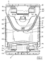
- Figure 1 shows in outline the structure of the operational track and the return track of a conveyor provided with an endless conveyor chain consisting of chain links.
- Beams sides 10a, 10b which in the illustrative embodiment are made of stainless steel and are of a standardized length or of a length tailored for a specific application, constitute the bearing parts of a guide arrangement 10 for the loadable operative part of the conveyor, i.e. the part on which the goods are transported, for example food products, e.g. milk, packed in consumer packages.
- Chain links 11 lying on guide edges 10c, 10d form an endless conveyor.
- the chain links are in principle of the type which have considerable mutual flexibility in the mutually connected state and which between them form through-openings or passages.
- Each chain link 11 has a pair of rod-shaped members 11a, 11b which, in the upper guide arrangement 10, lie under and run under the guide edges 10c, 10c.
- the beam sides 10a, 10b in the upper guide arrangement 10 have a substantially vertical upper portion 10a', 10b', a subsequent portion 10a", 10b" sloping relatively steeply in towards the centre, and a less steeply sloping end portion 10a"', 10b"'. All these portions are plane and merge into one another without forming any dirt-accumulating niches.
- connection piece 12 can be fitted in the desired position along the beam sides 10a, 10b without the need for holes in the beam sides and can also be used for joining adjacent beam sides.
- connection piece 12 comprises a first element 12a of substantially wedge-shaped external form in the parts 12a', 12a", and, as seen in Figure 1, with angles of convergence or inclination corresponding substantially to the angles of convergence or inclination of the sloping beam side portions 10a", 10a"'.
- connection piece 12 also comprises a second element 12b of the "female type" with a recess directed towards the element 12a and with a shape substantially complementing said external form of the element 12a.
- the outer design of the first element 12a of the connection piece i.e. the shape as viewed from the operative chain part, is gently sloping and rounded off without niches.
- the corresponding outer design of the second element 12b of the connection piece comprises only smooth and substantially vertical surfaces.
- connection piece 12 together form a unit which, in the state with the beam sides fitted, constitutes a self-draining connection piece, i.e. a connection piece without dirt-accumulating niches, and which, together with the beam sides 10a, 10b shaped in the manner described and leaving a drainage gap between them, gives a self-draining operative conveyor guide arrangement.
- a self-draining connection piece i.e. a connection piece without dirt-accumulating niches
- a vertical securing element 13 in the form of a tensioning bolt extending centrally through the elements 12a and 12b of the connection piece.
- This tensioning bolt tightens the elements 12a, 12b together and clamps the beam sides 10a, 10b between them with a wedge effect.
- the securing element 13 thus acts in a direction at right angles to the plane of the operative chain part.
- a seal 14 is inserted between cooperating surfaces 10a", 12a'; 10b", 12a' and 10a"', 12a"; 10b"', 12a” on the respective beam side 10a, 10b and the element 12a.
- the sealing element 14 also extends across the lower horizontal portion of the element 12a in Figure 1.
- the beam sides forming the operative chain guide are thus clamped securely together while leaving, as can be seen in Figure 1, a gap 15 between the lower longitudinal edges of the beam sides.
- connection pieces 12 Formed between the beam sides 10a, 10b there is a space, in principle wedge-shaped, which narrows in the direction towards the gap 15 and which has plane sloping surfaces, where any spillage from the product on the operative part of the chain 11 can freely flow from the chain to the gap 15.
- This gap 15 is interrupted only by, depending on the embodiment, one or more connection pieces 12 which, as has been mentioned above however, are of the self-draining type and thus give the whole beam construction a self-draining character despite the presence of these connection pieces.
- the second element 12b of the connection piece 12 has, at the bottom, a pair of bracket-like holders 16 which, in the illustrative embodiment shown, are produced separately and are screwed onto the element 12b.
- a second chain guide arrangement in the form of a return beam 17 for controlling and supporting the conveyor chain in the return direction is held in these holders 16.
- This return beam is in principle U-shaped and has the outside of its base part 17a directed towards the gap 15.
- the pins 11a, 11b of the chain links slide on the inwardly directed flanges 17b of the return beam 17.
- the return beam thus screens the underside of the conveyor chain from any contamination originating from spillage passing through the gap 15.
- FIG. 1 shows in principle, two small pins 18 (of which only one can be seen in the figure) are located centrally on the element 12a of the connection piece 12, near to the lower plane portion of the element 12a. These pins 18 are oriented in the longitudinal direction of the beam sides 10a, 10b and are intended to support an elongate element 19, in this embodiment a pipe of relatively small diameter, between adjacent connection pieces 12 or between a connection piece 12 and another arrangement along the conveyor, for example an end piece with deflector wheel.
- the elongate element 19 serves as protection against fingers or the like being inserted into the inside of the space between the beam sides.
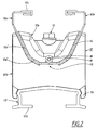
- Figure 2 corresponds in principle to Figure 1, with the only difference that the chain links have been omitted and that Figure 2 has been originally created by black/white CAD technology.
- the picture in Figure 1 is created using colour CAD and shows slightly more clearly the smoothly rounded self-draining form of the wedge-shaped element 12a of the connection piece.
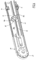
- Figure 3 shows two beam side lengths 10a, 10b joined together by means of the connection piece 12, and a chain return piece 20 at one end of the conveyor. At the other end of the conveyor there is a corresponding return piece which, like the conveyor frame, has not been shown in the figures.
- Figure 3 shows clearly that the return beam 17, i.e. the beam protecting the underside of the chain from contamination, has the same longitudinal extent as the beam sides 10a, 10b.
- Figure 3 also shows a deflector wheel 21 (another one is located in the encased part).
- the pins 11a, 11b on the chain links engage in recesses in these deflector wheels.
- the conveyor chain is normally driven at one end by means of the deflector wheels being provided with drive axles.
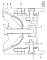
- Figure 4 is a longitudinal section through the arrangement in Figure 3 and shows clearly the details/elements described in connection with Figure 1. It will be seen, for example, that the element 19 protecting against insertion of fingers or the like extends all the way to the end piece and joins the latter.
- Figure 5 together with Figure 6 shows in detail the structure of a connection piece according to the invention.
- Figure 6 shows, for example, that the brackets 16 supporting the return beam are produced separately and can be inserted into complementary recesses in the element 12b.
- the brackets are secured with bolts 22 which are engaged in square nuts 23 which are held inside corresponding recesses in the element 12b.
- a further square nut 24 is shown which is intended to be placed inside the opening 25 so that, together with a bolt, it will support a vertical post serving as a pillar of a rail extending along the operative part of the conveyor.
- the tensioning bolt 13 shown in Figure 1 and discussed in connection with the latter has a corresponding square nut 26.
Landscapes
- Engineering & Computer Science (AREA)
- Mechanical Engineering (AREA)
- Framework For Endless Conveyors (AREA)
- Chain Conveyers (AREA)
- Attitude Control For Articles On Conveyors (AREA)
Abstract
Description
- The invention relates to conveyors intended for light goods, for example goods in the form of food products packed in consumer packages.
- Conveyors of the type in question include some form of endless chain or belt whose weight is supported by and which is controlled in a guide arrangement in a first direction, an operational direction. At both ends of the operational conveyor belt there are deflector wheels which give the chain/belt the necessary return direction. See for example the documents EP-A-0 203 352 and US-A-4 013 167.
- Hollow beams extruded in one piece with tailor-made inner profile and outer profile for producing guides for the operational belt and return belt for conveyor chains have been known for some time.
- It is likewise known to produce conveyors based on beam constructions composed of beam sides.
- These beam sides often have guide surfaces formed integrally with them and in themselves constitute an economical way of manufacturing conveyors for light goods, in the same way as said hollow beams extruded in one piece with inner and outer profiling.
- However, both types of conveyors constructed from beam elements have certain shortcomings, particularly in applications where a high level of hygiene is needed and has to be maintained throughout operation.
- The extruded, one-piece hollow beams with inner and outer profiling have, for example, internal spaces which are difficult to access for cleaning. The profiling additionally creates niches which gather dirt.
- The conveyor beams constructed from beam sides all have some type of bolt connection passing across the space between the beam sides. In addition to such bolt connections being needed to build individual beam length sections, some are also needed for joining the length sections. Since the necessary operational length of conveyor beams varies from application to application, the construction of a complete conveyor system using such beams means that alternative attachment points for transverse bolt connections have to be arranged in the beam sides. This results in the prefabricated beam sides being formed with longitudinal openings or slits to permit alternative points of attachment for bolt connections.
- The bolt connections together with the slits create points where dirt can gather and which can be difficult to access for cleaning purposes.
- The object of the invention is to make available a conveyor for light goods, where the conveyor satisfies stringent hygiene requirements, and where the conveyor, by means of self-draining during operation, maintains a high level of hygiene and, if need be, can be easily cleaned by simple means, without having to dismantle it and without having to interrupt operations.
- The object of the invention is achieved with the conveyor defined in attached
Patent Claim 1, and advantageous developments and embodiments of the most important parts of the conveyor are set out in Patent Claims 2-9. - Patent Claims 11-13 concern the connection piece according to the invention for connecting the beam sides of the conveyor.
-
- Figure 1
- is an outline diagram which at the top shows the conveyor guide for controlling the conveyor chain in the operational direction, and at the bottom shows the guide for the return direction. The figure also shows in outline the clamping arrangement which is located between said guides/beams for the beam sides included in the guide arrangement acting in the operational direction,
- Figure 2
- shows the arrangement from Figure 1 more clearly, but without conveyor chain links,
- Figure 3
- shows, in perspective view, part of a conveyor according to an embodiment of the invention provided with an end piece containing deflector wheels,
- Figure 4
- shows the arrangement from Figure 3 in sectional view in the longitudinal direction,
- Figure 5
- is a cross section through a tensioning arrangement/connection piece in one embodiment thereof, and
- Figure 6
- shows the tensioning arrangement/connection piece from Figure 5 in an exploded view.
- Figure 1 shows in outline the structure of the operational track and the return track of a conveyor provided with an endless conveyor chain consisting of chain links.
-
Beams sides guide arrangement 10 for the loadable operative part of the conveyor, i.e. the part on which the goods are transported, for example food products, e.g. milk, packed in consumer packages. -
Chain links 11 lying onguide edges chain link 11 has a pair of rod-shaped members upper guide arrangement 10, lie under and run under theguide edges - In Figure 1, the
beam sides upper guide arrangement 10 have a substantially verticalupper portion 10a', 10b', asubsequent portion 10a", 10b" sloping relatively steeply in towards the centre, and a less steeply slopingend portion 10a"', 10b"'. All these portions are plane and merge into one another without forming any dirt-accumulating niches. - To maintain the
beam sides more connection pieces 12 depending on the length of the beam sides. Theconnection piece 12 in Figure 1 can be fitted in the desired position along thebeam sides - The
connection piece 12 comprises afirst element 12a of substantially wedge-shaped external form in theparts 12a', 12a", and, as seen in Figure 1, with angles of convergence or inclination corresponding substantially to the angles of convergence or inclination of the slopingbeam side portions 10a", 10a"'. - The
connection piece 12 also comprises asecond element 12b of the "female type" with a recess directed towards theelement 12a and with a shape substantially complementing said external form of theelement 12a. - The outer design of the
first element 12a of the connection piece, i.e. the shape as viewed from the operative chain part, is gently sloping and rounded off without niches. The corresponding outer design of thesecond element 12b of the connection piece comprises only smooth and substantially vertical surfaces. - The two
elements connection piece 12 together form a unit which, in the state with the beam sides fitted, constitutes a self-draining connection piece, i.e. a connection piece without dirt-accumulating niches, and which, together with thebeam sides - As can be seen in principle in Figure 1, there is a
vertical securing element 13 in the form of a tensioning bolt extending centrally through theelements elements beam sides securing element 13 thus acts in a direction at right angles to the plane of the operative chain part. In the embodiment shown, aseal 14 is inserted betweencooperating surfaces 10a", 12a'; 10b", 12a' and 10a"', 12a"; 10b"', 12a" on therespective beam side element 12a. Thesealing element 14 also extends across the lower horizontal portion of theelement 12a in Figure 1. - With the described embodiment of
beam sides connection piece 12, the beam sides forming the operative chain guide are thus clamped securely together while leaving, as can be seen in Figure 1, agap 15 between the lower longitudinal edges of the beam sides. - Formed between the
beam sides gap 15 and which has plane sloping surfaces, where any spillage from the product on the operative part of thechain 11 can freely flow from the chain to thegap 15. Thisgap 15 is interrupted only by, depending on the embodiment, one ormore connection pieces 12 which, as has been mentioned above however, are of the self-draining type and thus give the whole beam construction a self-draining character despite the presence of these connection pieces. - The
second element 12b of theconnection piece 12 has, at the bottom, a pair of bracket-like holders 16 which, in the illustrative embodiment shown, are produced separately and are screwed onto theelement 12b. A second chain guide arrangement in the form of areturn beam 17 for controlling and supporting the conveyor chain in the return direction is held in theseholders 16. This return beam is in principle U-shaped and has the outside of itsbase part 17a directed towards thegap 15. Thepins flanges 17b of thereturn beam 17. The return beam thus screens the underside of the conveyor chain from any contamination originating from spillage passing through thegap 15. - As Figure 1 shows in principle, two small pins 18 (of which only one can be seen in the figure) are located centrally on the
element 12a of theconnection piece 12, near to the lower plane portion of theelement 12a. Thesepins 18 are oriented in the longitudinal direction of thebeam sides elongate element 19, in this embodiment a pipe of relatively small diameter, betweenadjacent connection pieces 12 or between aconnection piece 12 and another arrangement along the conveyor, for example an end piece with deflector wheel. Theseelongate elements 19, which in Figure 1 lie above thegap 15, reduce the gap width, as viewed from below in the figure, but still leave, at eachconnection piece 12 and along the whole gap between connection pieces or equivalent, a flow passage for contaminants and of course the cleaning agent which may be used, for example pressurized water or steam. - The
elongate element 19 serves as protection against fingers or the like being inserted into the inside of the space between the beam sides. - Having described the basic structure of the load-
bearing guide arrangement 10 of the conveyor, its returnbeam guide arrangement 17 and itsconnection piece 12, reference is now made to Figures 2-7 for further explanation of the construction. - Figure 2 corresponds in principle to Figure 1, with the only difference that the chain links have been omitted and that Figure 2 has been originally created by black/white CAD technology. The picture in Figure 1 is created using colour CAD and shows slightly more clearly the smoothly rounded self-draining form of the wedge-shaped
element 12a of the connection piece. - Figure 3 shows two
beam side lengths connection piece 12, and achain return piece 20 at one end of the conveyor. At the other end of the conveyor there is a corresponding return piece which, like the conveyor frame, has not been shown in the figures. - From what has been described, it should already be clear that such a frame is normally arranged to support the chain parts, the operative part and the return part in a horizontal plane.
- Figure 3 shows clearly that the
return beam 17, i.e. the beam protecting the underside of the chain from contamination, has the same longitudinal extent as thebeam sides - Figure 3 also shows a deflector wheel 21 (another one is located in the encased part). The
pins - Figure 4 is a longitudinal section through the arrangement in Figure 3 and shows clearly the details/elements described in connection with Figure 1. It will be seen, for example, that the
element 19 protecting against insertion of fingers or the like extends all the way to the end piece and joins the latter. - Figure 5 together with Figure 6 shows in detail the structure of a connection piece according to the invention.
- Figure 6 shows, for example, that the
brackets 16 supporting the return beam are produced separately and can be inserted into complementary recesses in theelement 12b. The brackets are secured withbolts 22 which are engaged insquare nuts 23 which are held inside corresponding recesses in theelement 12b. - A further
square nut 24 is shown which is intended to be placed inside theopening 25 so that, together with a bolt, it will support a vertical post serving as a pillar of a rail extending along the operative part of the conveyor. - The
tensioning bolt 13 shown in Figure 1 and discussed in connection with the latter has a correspondingsquare nut 26. - In the introduction, and in the description of the different figures in the drawing, mention has been made of certain design details, including choice of material, etc. However, it will be appreciated that the concept of the invention is not limited to the examples which have been given, and instead the invention is limited only by what is specified in the attached patent claims.
Claims (13)
- Conveyor for light goods, for example food products packed in consumer packages, comprising an endless conveyor chain (11), a supporting first guide arrangement (10) for controlling the conveyor chain in an operational direction with goods intended to be placed on the conveyor chain, a second guide arrangement (17) for controlling the conveyor chain in the return direction, and a deflector wheel arrangement (20) at both ends of the first and second guide arrangements, characterized in that:the supporting guide arrangement comprises a pair of parallel elongate plate-shaped elements serving as beam sides (10, 10b),the beam sides between them form a space which at least partially narrows in the direction towards the second guide arrangement (17),at least one first connection piece element (12a), with an external shape corresponding to said narrowing space, bears against the inside surfaces of the beam sides (10a, 10b),at least one second connection piece element (12b) at least partially adapted in shape surrounds said first element (12a) and accommodates, between itself and the first element, the pair of beam sides (10a, 10b), anda securing element (13) is arranged substantially at right angles to the plane of the conveyor chain of the first guide arrangement in order to tighten the first and second elements (12a, 12b) together and clamp the beam sides (10a, 10b) lying between them.
- Conveyor according to Claim 1, characterized in that said first guide arrangement (10) comprising the beam sides has a drainage gap (15) between the beam sides (10a, 10b) in the direction towards the second guide arrangement (17) along the entire length of the beam sides, with interruption for arrangement of said at least one first (12a) and second (12b) elements clamping the beam sides.
- Conveyor according to Claim 2, characterized in that the second guide arrangement (17), via part (17a) thereof, completely covers the underside of the conveyor chain on the side directed towards the drainage gap (15).
- Conveyor according to Claim 3, characterized in that the first (12a) and second (12b) elements clamping the beam sides are designed with niche-free external outer surfaces, of such shape and orientation that a self-draining join is formed between the first (10) and second (17) guide arrangement.
- Conveyor according to Claim 4, characterized in that the second guide arrangement (17) comprises a beam forming a substantial U profile, and in that said at least one second element (12b) of the clamping arrangement (12) has means (16) for supporting the U-beam with the outside of its base part directed towards the drainage gap (15).
- Conveyor according to Claim 5, characterized in that said at least one first element (12a) of the clamping arrangement has means (18) for securing an elongate safety element (19) which prevents insertion of fingers or the like into the drainage gap (15) but permits drainage, and which extends internally in the space between the beam sides (10a, 10b) along the whole of the drainage gap (15), at a short distance from it.
- Conveyor according to one or more of the preceding claims, characterized in that the first element (12a) of said clamping arrangement is substantially wedge-shaped with external bearing surfaces lying against the inside surfaces of the beam sides provided with a seal (14).
- Conveyor according to Claim 7, characterized in that the second element (12b) of said clamping arrangement has, at one end, a recess corresponding to said external bearing surfaces (12a', 12") and, at the opposite end, said means (16) for supporting the U-profile beam (17) protecting the conveyor chain (11) in the return direction against contamination.
- Conveyor according to Claim 8, characterized in that the securing element (13) for clamping is a tensioning bolt arranged centrally in the wedge-shaped element (12a) and the complementary element (12b).
- Connection piece for supporting chain-guide arrangement (10) in a conveyor for light goods, where said chain-guide arrangement comprises a pair of parallel elongate plate-shaped elements serving as beam sides (10a, 10b), characterized by:a first element (12a) with external shape (12a', 12a") corresponding to a space between the beam sides (10a, 10b) which narrows in the direction towards a return chain-guide arrangement (17) in the conveyor concerned, and with an external part of said first element (12a) intended to bear directly or indirectly against the inside surfaces of the beam sides (10a, 10b),a second element (12b) which, at least partially adapted in shape, encloses said first element (12a) and, between itself and the first element, accommodates the pair of beam sides (10a, 10b), anda securing element (13) which is intended to tighten the first and second elements together and clamp the intermediate beam sides (10a, 10b) between them, and which is arranged substantially at right angles to the chain-supporting plane of the first guide arrangement (10).
- Connection piece according to Claim 10, characterized in that the first element (12a) of the connection piece is substantially wedge-shaped with external bearing surfaces (12a', 12a") lying against the inside surfaces of the beam sides provided with a seal (14).
- Connection piece according to Claim 11, characterized in that the second element (12b) of the connection piece has, at one end, a recess corresponding to said external bearing surfaces (12a', 12a"), and, at the opposite end, means (16) for supporting a U-profile beam (17) protecting the conveyor chain in the return direction against contamination.
- Connection piece according to Claim 12, characterized in that the securing element (13) for clamping is a tensioning bolt arranged centrally in the wedge-shaped element (12a) and the complementary element (12b).
Applications Claiming Priority (3)
| Application Number | Priority Date | Filing Date | Title |
|---|---|---|---|
| SE0102091A SE519179C2 (en) | 2001-06-13 | 2001-06-13 | Conveyor and connecting piece to conveyor beam sides |
| SE0102091 | 2001-06-13 | ||
| PCT/SE2002/001101 WO2002100746A1 (en) | 2001-06-13 | 2002-06-07 | Conveyor, and connection piece for conveyor beam sides |
Publications (2)
| Publication Number | Publication Date |
|---|---|
| EP1395507A1 EP1395507A1 (en) | 2004-03-10 |
| EP1395507B1 true EP1395507B1 (en) | 2006-10-04 |
Family
ID=20284459
Family Applications (1)
| Application Number | Title | Priority Date | Filing Date |
|---|---|---|---|
| EP02733755A Expired - Lifetime EP1395507B1 (en) | 2001-06-13 | 2002-06-07 | Conveyor, and connection piece for conveyor beam sides |
Country Status (9)
| Country | Link |
|---|---|
| US (1) | US6913139B2 (en) |
| EP (1) | EP1395507B1 (en) |
| JP (1) | JP3962015B2 (en) |
| CN (1) | CN1251947C (en) |
| AT (1) | ATE341504T1 (en) |
| DE (1) | DE60215159T2 (en) |
| ES (1) | ES2274033T3 (en) |
| SE (1) | SE519179C2 (en) |
| WO (1) | WO2002100746A1 (en) |
Families Citing this family (4)
| Publication number | Priority date | Publication date | Assignee | Title |
|---|---|---|---|---|
| FR2881410B1 (en) * | 2005-02-03 | 2007-10-26 | Norcan Sa | DEVICE FOR GUIDING MODULAR BANDS OF CONVEYORS |
| US20090101478A1 (en) * | 2007-10-23 | 2009-04-23 | Christopher Dale | Inline conveyor scale |
| DK177306B1 (en) * | 2010-11-02 | 2012-11-12 | Flexmove System M Sdn Bhd | Conveyor |
| US8662292B2 (en) * | 2011-09-26 | 2014-03-04 | Service Industries, LLC | Conveyor belt assembly |
Family Cites Families (7)
| Publication number | Priority date | Publication date | Assignee | Title |
|---|---|---|---|---|
| US4013167A (en) * | 1975-05-21 | 1977-03-22 | Custom Fabricators, Inc. | Conveyor support structure |
| SE8405826L (en) * | 1984-11-20 | 1986-05-21 | Skf Ab | TRANSPORTATION DEVICE WITH MULTIPLE TRANSPORTOR Beam |
| DE3518134A1 (en) | 1985-05-21 | 1986-11-27 | Robert Bosch Gmbh, 7000 Stuttgart | GUIDE PROFILE FOR A CONVEYOR BELT |
| US5131531A (en) * | 1990-12-27 | 1992-07-21 | Dynamic Conveyor Corporation | Modular conveyor |
| US5443151A (en) * | 1994-03-30 | 1995-08-22 | Gorbel, Inc. | Conveyor or crane beam of extruded aluminum alloy |
| US5755246A (en) * | 1995-06-23 | 1998-05-26 | George Koch Sons, Inc. | Housing for industrial finishing equipment |
| FI106113B (en) * | 1999-02-22 | 2000-11-30 | Kci Kone Cranes Int Oy | Profile rail connection |
-
2001
- 2001-06-13 SE SE0102091A patent/SE519179C2/en not_active IP Right Cessation
-
2002
- 2002-06-07 AT AT02733755T patent/ATE341504T1/en not_active IP Right Cessation
- 2002-06-07 EP EP02733755A patent/EP1395507B1/en not_active Expired - Lifetime
- 2002-06-07 CN CN02811835.9A patent/CN1251947C/en not_active Expired - Fee Related
- 2002-06-07 JP JP2003503523A patent/JP3962015B2/en not_active Expired - Fee Related
- 2002-06-07 WO PCT/SE2002/001101 patent/WO2002100746A1/en not_active Ceased
- 2002-06-07 DE DE60215159T patent/DE60215159T2/en not_active Expired - Lifetime
- 2002-06-07 ES ES02733755T patent/ES2274033T3/en not_active Expired - Lifetime
- 2002-06-07 US US10/480,336 patent/US6913139B2/en not_active Expired - Fee Related
Also Published As
| Publication number | Publication date |
|---|---|
| DE60215159T2 (en) | 2007-08-23 |
| ES2274033T3 (en) | 2007-05-16 |
| EP1395507A1 (en) | 2004-03-10 |
| US6913139B2 (en) | 2005-07-05 |
| SE0102091L (en) | 2002-12-14 |
| ATE341504T1 (en) | 2006-10-15 |
| CN1516672A (en) | 2004-07-28 |
| US20040238334A1 (en) | 2004-12-02 |
| WO2002100746A1 (en) | 2002-12-19 |
| DE60215159D1 (en) | 2006-11-16 |
| SE519179C2 (en) | 2003-01-28 |
| JP3962015B2 (en) | 2007-08-22 |
| CN1251947C (en) | 2006-04-19 |
| JP2004528254A (en) | 2004-09-16 |
| SE0102091D0 (en) | 2001-06-13 |
Similar Documents
| Publication | Publication Date | Title |
|---|---|---|
| CA1080143A (en) | Structural element | |
| EP1277676B1 (en) | Snap-on side guards | |
| US5311983A (en) | Conveyor frame with drive housing | |
| JP3809191B2 (en) | Conveyor belt | |
| EP1264786B1 (en) | Flat hinge module for conveyor belts | |
| US6595351B2 (en) | Pusher for scraper chain conveyors, especially for underground mining | |
| US6913139B2 (en) | Conveyor, and connection piece for conveyor beam sides | |
| GB2210595A (en) | Wire mesh belt and slicer | |
| CA2412058C (en) | Modular conveyor with radius turn module and method of assembly | |
| US20020195321A1 (en) | Flush Grid belt module | |
| WO2002002440A1 (en) | Slide rail device for a conveyor | |
| ES2311100T3 (en) | CONVEYER BELT. | |
| CN1964905A (en) | Pasteuriser with conveyor belt | |
| US7275638B2 (en) | Method and blank for manufacturing a bent curve element, bent curve element, curve unit comprising a bent curve element and also conveying track comprising such a curve unit | |
| US7225918B2 (en) | Transport device for transporting goods, preferably on pallets, comprising two laterally peripheral traction elements, especially transport chains | |
| CA2388945C (en) | Flat top open hinge module | |
| KR970704923A (en) | Shaft device | |
| US7048112B2 (en) | Food grade conveyor | |
| FR2476042A1 (en) | Belt conveyor mounted on standard sections - is fitted with track for longitudinal processing lines below support beam | |
| SU1685833A1 (en) | Belt conveyor frame | |
| JP3309488B2 (en) | Conversion device | |
| US11459177B2 (en) | Conveyor bracket | |
| GB2105282A (en) | Connecting conveyor elements to conveyor chain | |
| JPH07329773A (en) | Trolley conveyor |
Legal Events
| Date | Code | Title | Description |
|---|---|---|---|
| PUAI | Public reference made under article 153(3) epc to a published international application that has entered the european phase |
Free format text: ORIGINAL CODE: 0009012 |
|
| 17P | Request for examination filed |
Effective date: 20031213 |
|
| AK | Designated contracting states |
Kind code of ref document: A1 Designated state(s): AT BE CH CY DE DK ES FI FR GB GR IE IT LI LU MC NL PT SE TR |
|
| AX | Request for extension of the european patent |
Extension state: AL LT LV MK RO SI |
|
| GRAP | Despatch of communication of intention to grant a patent |
Free format text: ORIGINAL CODE: EPIDOSNIGR1 |
|
| GRAS | Grant fee paid |
Free format text: ORIGINAL CODE: EPIDOSNIGR3 |
|
| GRAA | (expected) grant |
Free format text: ORIGINAL CODE: 0009210 |
|
| AK | Designated contracting states |
Kind code of ref document: B1 Designated state(s): AT BE CH CY DE DK ES FI FR GB GR IE IT LI LU MC NL PT SE TR |
|
| PG25 | Lapsed in a contracting state [announced via postgrant information from national office to epo] |
Ref country code: IT Free format text: LAPSE BECAUSE OF FAILURE TO SUBMIT A TRANSLATION OF THE DESCRIPTION OR TO PAY THE FEE WITHIN THE PRESCRIBED TIME-LIMIT;WARNING: LAPSES OF ITALIAN PATENTS WITH EFFECTIVE DATE BEFORE 2007 MAY HAVE OCCURRED AT ANY TIME BEFORE 2007. THE CORRECT EFFECTIVE DATE MAY BE DIFFERENT FROM THE ONE RECORDED. Effective date: 20061004 Ref country code: LI Free format text: LAPSE BECAUSE OF FAILURE TO SUBMIT A TRANSLATION OF THE DESCRIPTION OR TO PAY THE FEE WITHIN THE PRESCRIBED TIME-LIMIT Effective date: 20061004 Ref country code: BE Free format text: LAPSE BECAUSE OF FAILURE TO SUBMIT A TRANSLATION OF THE DESCRIPTION OR TO PAY THE FEE WITHIN THE PRESCRIBED TIME-LIMIT Effective date: 20061004 Ref country code: NL Free format text: LAPSE BECAUSE OF FAILURE TO SUBMIT A TRANSLATION OF THE DESCRIPTION OR TO PAY THE FEE WITHIN THE PRESCRIBED TIME-LIMIT Effective date: 20061004 Ref country code: FI Free format text: LAPSE BECAUSE OF FAILURE TO SUBMIT A TRANSLATION OF THE DESCRIPTION OR TO PAY THE FEE WITHIN THE PRESCRIBED TIME-LIMIT Effective date: 20061004 Ref country code: CH Free format text: LAPSE BECAUSE OF FAILURE TO SUBMIT A TRANSLATION OF THE DESCRIPTION OR TO PAY THE FEE WITHIN THE PRESCRIBED TIME-LIMIT Effective date: 20061004 Ref country code: AT Free format text: LAPSE BECAUSE OF FAILURE TO SUBMIT A TRANSLATION OF THE DESCRIPTION OR TO PAY THE FEE WITHIN THE PRESCRIBED TIME-LIMIT Effective date: 20061004 |
|
| REG | Reference to a national code |
Ref country code: GB Ref legal event code: FG4D |
|
| REG | Reference to a national code |
Ref country code: CH Ref legal event code: EP |
|
| REG | Reference to a national code |
Ref country code: IE Ref legal event code: FG4D |
|
| REF | Corresponds to: |
Ref document number: 60215159 Country of ref document: DE Date of ref document: 20061116 Kind code of ref document: P |
|
| PG25 | Lapsed in a contracting state [announced via postgrant information from national office to epo] |
Ref country code: DK Free format text: LAPSE BECAUSE OF FAILURE TO SUBMIT A TRANSLATION OF THE DESCRIPTION OR TO PAY THE FEE WITHIN THE PRESCRIBED TIME-LIMIT Effective date: 20070104 Ref country code: SE Free format text: LAPSE BECAUSE OF FAILURE TO SUBMIT A TRANSLATION OF THE DESCRIPTION OR TO PAY THE FEE WITHIN THE PRESCRIBED TIME-LIMIT Effective date: 20070104 |
|
| PG25 | Lapsed in a contracting state [announced via postgrant information from national office to epo] |
Ref country code: PT Free format text: LAPSE BECAUSE OF FAILURE TO SUBMIT A TRANSLATION OF THE DESCRIPTION OR TO PAY THE FEE WITHIN THE PRESCRIBED TIME-LIMIT Effective date: 20070316 |
|
| NLV1 | Nl: lapsed or annulled due to failure to fulfill the requirements of art. 29p and 29m of the patents act | ||
| REG | Reference to a national code |
Ref country code: CH Ref legal event code: PL |
|
| ET | Fr: translation filed | ||
| REG | Reference to a national code |
Ref country code: ES Ref legal event code: FG2A Ref document number: 2274033 Country of ref document: ES Kind code of ref document: T3 |
|
| PLBE | No opposition filed within time limit |
Free format text: ORIGINAL CODE: 0009261 |
|
| STAA | Information on the status of an ep patent application or granted ep patent |
Free format text: STATUS: NO OPPOSITION FILED WITHIN TIME LIMIT |
|
| 26N | No opposition filed |
Effective date: 20070705 |
|
| PG25 | Lapsed in a contracting state [announced via postgrant information from national office to epo] |
Ref country code: MC Free format text: LAPSE BECAUSE OF NON-PAYMENT OF DUE FEES Effective date: 20070630 |
|
| PG25 | Lapsed in a contracting state [announced via postgrant information from national office to epo] |
Ref country code: GR Free format text: LAPSE BECAUSE OF FAILURE TO SUBMIT A TRANSLATION OF THE DESCRIPTION OR TO PAY THE FEE WITHIN THE PRESCRIBED TIME-LIMIT Effective date: 20070105 |
|
| PG25 | Lapsed in a contracting state [announced via postgrant information from national office to epo] |
Ref country code: IE Free format text: LAPSE BECAUSE OF NON-PAYMENT OF DUE FEES Effective date: 20070607 |
|
| PG25 | Lapsed in a contracting state [announced via postgrant information from national office to epo] |
Ref country code: LU Free format text: LAPSE BECAUSE OF NON-PAYMENT OF DUE FEES Effective date: 20070607 Ref country code: CY Free format text: LAPSE BECAUSE OF FAILURE TO SUBMIT A TRANSLATION OF THE DESCRIPTION OR TO PAY THE FEE WITHIN THE PRESCRIBED TIME-LIMIT Effective date: 20061004 |
|
| PG25 | Lapsed in a contracting state [announced via postgrant information from national office to epo] |
Ref country code: TR Free format text: LAPSE BECAUSE OF FAILURE TO SUBMIT A TRANSLATION OF THE DESCRIPTION OR TO PAY THE FEE WITHIN THE PRESCRIBED TIME-LIMIT Effective date: 20061004 |
|
| REG | Reference to a national code |
Ref country code: FR Ref legal event code: PLFP Year of fee payment: 15 |
|
| REG | Reference to a national code |
Ref country code: FR Ref legal event code: PLFP Year of fee payment: 16 |
|
| REG | Reference to a national code |
Ref country code: FR Ref legal event code: PLFP Year of fee payment: 17 |
|
| PGFP | Annual fee paid to national office [announced via postgrant information from national office to epo] |
Ref country code: FR Payment date: 20180626 Year of fee payment: 17 |
|
| PGFP | Annual fee paid to national office [announced via postgrant information from national office to epo] |
Ref country code: ES Payment date: 20180702 Year of fee payment: 17 Ref country code: GB Payment date: 20180627 Year of fee payment: 17 Ref country code: IT Payment date: 20180621 Year of fee payment: 17 Ref country code: DE Payment date: 20180627 Year of fee payment: 17 |
|
| REG | Reference to a national code |
Ref country code: DE Ref legal event code: R119 Ref document number: 60215159 Country of ref document: DE |
|
| GBPC | Gb: european patent ceased through non-payment of renewal fee |
Effective date: 20190607 |
|
| PG25 | Lapsed in a contracting state [announced via postgrant information from national office to epo] |
Ref country code: IT Free format text: LAPSE BECAUSE OF NON-PAYMENT OF DUE FEES Effective date: 20190607 Ref country code: DE Free format text: LAPSE BECAUSE OF NON-PAYMENT OF DUE FEES Effective date: 20200101 Ref country code: GB Free format text: LAPSE BECAUSE OF NON-PAYMENT OF DUE FEES Effective date: 20190607 |
|
| PG25 | Lapsed in a contracting state [announced via postgrant information from national office to epo] |
Ref country code: FR Free format text: LAPSE BECAUSE OF NON-PAYMENT OF DUE FEES Effective date: 20190630 |
|
| REG | Reference to a national code |
Ref country code: ES Ref legal event code: FD2A Effective date: 20201027 |
|
| PG25 | Lapsed in a contracting state [announced via postgrant information from national office to epo] |
Ref country code: ES Free format text: LAPSE BECAUSE OF NON-PAYMENT OF DUE FEES Effective date: 20190608 |