EP1395456B1 - Power take-off in a motor driven vehicle - Google Patents
Power take-off in a motor driven vehicle Download PDFInfo
- Publication number
- EP1395456B1 EP1395456B1 EP02733729A EP02733729A EP1395456B1 EP 1395456 B1 EP1395456 B1 EP 1395456B1 EP 02733729 A EP02733729 A EP 02733729A EP 02733729 A EP02733729 A EP 02733729A EP 1395456 B1 EP1395456 B1 EP 1395456B1
- Authority
- EP
- European Patent Office
- Prior art keywords
- pto
- shaft
- ridges
- unit
- gearwheel
- Prior art date
- Legal status (The legal status is an assumption and is not a legal conclusion. Google has not performed a legal analysis and makes no representation as to the accuracy of the status listed.)
- Expired - Lifetime
Links
- 230000002093 peripheral effect Effects 0.000 claims description 21
- 230000005540 biological transmission Effects 0.000 claims description 14
- 230000007423 decrease Effects 0.000 claims description 4
- 230000033001 locomotion Effects 0.000 description 9
- 230000008878 coupling Effects 0.000 description 2
- 238000010168 coupling process Methods 0.000 description 2
- 238000005859 coupling reaction Methods 0.000 description 2
- 230000000295 complement effect Effects 0.000 description 1
- 239000000470 constituent Substances 0.000 description 1
- 238000004519 manufacturing process Methods 0.000 description 1
Images

Classifications
-
- B—PERFORMING OPERATIONS; TRANSPORTING
- B60—VEHICLES IN GENERAL
- B60K—ARRANGEMENT OR MOUNTING OF PROPULSION UNITS OR OF TRANSMISSIONS IN VEHICLES; ARRANGEMENT OR MOUNTING OF PLURAL DIVERSE PRIME-MOVERS IN VEHICLES; AUXILIARY DRIVES FOR VEHICLES; INSTRUMENTATION OR DASHBOARDS FOR VEHICLES; ARRANGEMENTS IN CONNECTION WITH COOLING, AIR INTAKE, GAS EXHAUST OR FUEL SUPPLY OF PROPULSION UNITS IN VEHICLES
- B60K17/00—Arrangement or mounting of transmissions in vehicles
- B60K17/28—Arrangement or mounting of transmissions in vehicles characterised by arrangement, location, or type of power take-off
-
- F—MECHANICAL ENGINEERING; LIGHTING; HEATING; WEAPONS; BLASTING
- F16—ENGINEERING ELEMENTS AND UNITS; GENERAL MEASURES FOR PRODUCING AND MAINTAINING EFFECTIVE FUNCTIONING OF MACHINES OR INSTALLATIONS; THERMAL INSULATION IN GENERAL
- F16D—COUPLINGS FOR TRANSMITTING ROTATION; CLUTCHES; BRAKES
- F16D3/00—Yielding couplings, i.e. with means permitting movement between the connected parts during the drive
- F16D3/16—Universal joints in which flexibility is produced by means of pivots or sliding or rolling connecting parts
- F16D3/18—Universal joints in which flexibility is produced by means of pivots or sliding or rolling connecting parts the coupling parts (1) having slidably-interengaging teeth
- F16D3/185—Universal joints in which flexibility is produced by means of pivots or sliding or rolling connecting parts the coupling parts (1) having slidably-interengaging teeth radial teeth connecting concentric inner and outer coupling parts
-
- B—PERFORMING OPERATIONS; TRANSPORTING
- B60—VEHICLES IN GENERAL
- B60K—ARRANGEMENT OR MOUNTING OF PROPULSION UNITS OR OF TRANSMISSIONS IN VEHICLES; ARRANGEMENT OR MOUNTING OF PLURAL DIVERSE PRIME-MOVERS IN VEHICLES; AUXILIARY DRIVES FOR VEHICLES; INSTRUMENTATION OR DASHBOARDS FOR VEHICLES; ARRANGEMENTS IN CONNECTION WITH COOLING, AIR INTAKE, GAS EXHAUST OR FUEL SUPPLY OF PROPULSION UNITS IN VEHICLES
- B60K25/00—Auxiliary drives
- B60K25/06—Auxiliary drives from the transmission power take-off
Definitions
- the invention relates to a power take-off on an engine-driven vehicle according to the preamble to claim 1.
- PTOs Power take-offs
- the PTO's driving power is usually obtained from the vehicle's driveline via a transmission element in the vehicle's gearbox.
- the PTO is usually connected to a hydraulic pump which itself drives said auxiliary equipment.
- a known PTO on a vehicle incorporates a first unit with a bearing bracket which supports a gearwheel which is mounted in engagement with a gearwheel of the vehicle's gearbox.
- the bearing bracket is fastened to a sidewall of the gearbox.
- the gearwheel of the first unit incorporates a hub which is in engagement with a first end of a shaft via a first spline connection.
- the other end of the shaft is in engagement with a corresponding hub of a second unit via a second spline connection.
- the second unit is mounted adjacent to a rear edge of the gearbox and incorporates suitable connecting means for connecting and driving a hydraulic pump.
- the hub of the gearwheel of the first unit and the hub of the second unit are in line here so that said shaft allows here the transmission of a driving motion.
- the bearing bracket is provided with a gearwheel of a size and a number of teeth as required for providing the PTO with the desired output speed.
- the bearing bracket is thus provided with a smaller gearwheel with a smaller number of teeth.
- a specially adapted bearing bracket is required for the smaller gearwheel.
- the closest prior art US 4 453 830 shows to a transmission for driving a concrete mixer drum on a vehicle.
- the transmission comprises a shaft provided with arcuate splines at its ends portions.
- the shaft may be angulary adjusted such that it is possible to maintain the driving operation of the drum even when relative motions between the drum and the transmission housing occur.
- the object of the present invention is to provide a PTO on a motor vehicle which incorporates a number of basic components which may substantially always be fitted in the motor vehicle even when PTOs are manufactured with different output speeds.
- a spline connection allows a certain axial mobility between the constituent parts of the spline connection.
- the same shaft may therefore be used for bridging the distance between the two hubs which have parallel centrelines even if one hub protrudes laterally relative to the second hub so that the centrelines of the hubs are no longer in line with one another.
- Appropriate design of the spline connection makes it possible for one shaft to be angled so that it can in this case receive a driving motion from the first hub and transmit it to the second hub.
- the shaft can also transmit a driving motion between the first and second units when the hubs have assumed different rotational positions relative to one another.
- the PTO may incorporate a shaft and a number of basic components which may always be fitted in a vehicle even when PTOs with different output speeds are manufactured, resulting in the position of the first hub being altered. The cost of manufacturing PTOs with different output speeds is thus significantly reduced by the increased possibility of modularisation of the relevant components.
- the first portion and second portion of the shaft may be positioned at substantially continuously variable angles to the accommodating recesses in the hub within an angular range.
- the first portion and second portion of the shaft may with advantage be angled within an angular range of at least ⁇ 5% to the hubs of the accommodating recesses.
- the first portion and second portion of the shaft preferably incorporate a peripheral surface which comprises a number of ridges which are mainly axial in extent and which exhibit a peripheral surface which in an axial direction is situated at a variable radial distance from a centreline through the shaft.
- first and second portions of the shaft may incorporate a conventional spline design with straight ridges while the recesses of the hubs incorporate grooves with a peripheral surface which is situated at a variable radial distance from a centreline through the recesses of the hubs.
- Such a shape of the grooves also makes possible a continuous oblique positioning of the first and second portions of the shaft in the recesses.
- the peripheral surface of the ridges exhibits a maximum distance from the centreline at an axial intermediate position which is situated between the axial end positions of the ridges.
- the portion of the ridges which exhibits said maximum radial distance is substantially only in engagement with the grooves of the recesses.
- the engaging portions of the ridges protrude partly from said axial middle position.
- first and second portions of the shaft can be angled so much that substantially the whole axial extent of the ridges can be used.
- the peripheral surfaces of the ridges exhibit part of a circular path between the axial end positions.
- the first and second portions of the shaft can be positioned obliquely continuously in the recesses, which may here exhibit a conventional spline design with straight grooves to accommodate said ridges. Only the spline design of the first and second portions of the shaft need be modified relative to a conventional PTO design.
- the motion-transmitting element of the first unit is a gearwheel.
- a gearwheel ofsubstantially any desired size may here be arranged in engagement with a transmission element of the vehicle.
- Said transmission element is a gearwheel in a gearbox.
- the transmission element is with advantage the forward gearwheel on the gearbox's countershaft.
- the gearwheel is fastened to the gearbox by means of a bearing bracket.
- the same bearing bracket can be used for gearwheels of different sizes. Significant economies may thus be made.
- said item driven by the PTO is a hydraulic pump. Hydraulic operation is often preferable on vehicles which incorporate auxiliary equipment of various kinds.
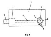
- Fig. 1 depicts schematically a PTO which is fastened to a gearbox 1 forming part of a driveline of a motor vehicle, and which is therefore driven by the vehicle's engine.
- the PTO incorporates a first unit 2 which comprises a bearing bracket 3 which is fastened by bolts 4 to a sidewall of the gearbox 1.
- the bearing bracket 3 supports a gearwheel 5 which is in engagement with the forward gearwheel 1' on the countershaft of the gearbox 1.
- the forward gearwheel 1' of the gearbox 1 is depicted schematically in Fig. 2.
- the PTO further incorporates a shaft 6 about 60 cm long which extends from the first unit 2 to a second unit 7.
- the second unit 7 of the PTO is fastened to a rear wall of the gearbox 1 and incorporates connecting means for connecting a hydraulic motor 8 to the PTO in order to drive auxiliary equipment of the vehicle.
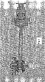
- Fig. 2 depicts the design of the PTO in more detail.
- the bearing bracket 3 is thus fastenable to the gearbox 1 by means of bolts 4.
- the bearing bracket 3 supports the gearwheel 5 for rotation via two bearings 9.
- the gearwheel 5 incorporates a centrally situated hub 10 connected firmly to the gearwheel 5.
- the hub 10 incorporates a central recess with a radial internal surface whose shape is such as to form part of a first spline connection of the PTO.
- the shaft 6 incorporates a first homogeneous section 11 which incorporates a first end portion 12.
- the first end portion 12 exhibits an external radial surface whose shape is such as to form a complementing part of the first spline connection.
- the first spline connection thus transmits the rotary motion of the gearwheel 5 and the hub 10 to the shaft 6.
- the shaft 6 incorporates a tubular middle section 13 which is thus firmly connected on one side to the first homogeneous section 11.
- the tubular middle section 13 is firmly connected on the opposite side to the other homogeneous section 14.
- the homogeneous section 14 incorporates a second end portion 15 which exhibits a radial external surface whose shape is such as to form part of a second spline connection.
- the PTO's second unit 7 incorporates a fastening element 16 designed to be fastened by bolts to a rear wall of the gearbox 1.
- the fastening element 16 incorporates bearings 17 by means of which a hub 18 is arranged for rotation relative to the fastening element 16.
- the hub 18 incorporates a central recess with a radial internal surface whose shape is such as to form a complementary part of the second spline connection.
- the second spline connection thus transmits the rotary motion of the shaft 6 to the hub 18.
- the hub 18 is connected for rotation with an output shaft 19 and a coupling plate 20 for connecting the hydraulic pump 8.
- Fig. 3 depicts a section of the shaft 6 which incorporates the first end portion 12.
- the first end portion 12 incorporates an external peripheral surface with a multiplicity of ridges 21 which have a substantially axial extent.
- the ridges 21 are arranged round the surface of the first end portion 12 at substantially constant intervals.
- the ridges 21 incorporate a peripheral surface which exhibits along its axial extent a varying radial distance from a centreline 22 through the shaft 6.
- the peripheral surface of the ridges 21 exhibits at an axially middle position 23 situated substantially halfway between the axial end positions 24,25 of the ridges 21 a maximum radial distance from the centreline 22.
- the radial distance of the ridges 21 from the centreline 22 decreases continuously along substantially circular paths from the axial intermediate position 23 to the axial end positions 24,25.
- Fig. 4 depicts the first end portion 12 of the shaft as seen from the left side in Fig. 3.
- the first end portion 12 incorporates an intermediate surface 26 which extends between the ridges 21.
- the intermediate surface 26 also exhibits along its axial extent a varying radial distance from the centreline 22 through the shaft 6.
- the radial distance of the intermediate surface 26 from the centreline varies in a manner corresponding to the distance of the peripheral surface of the ridges 21.
- the height of the ridges 21, i.e. the distance between the peripheral surface of the ridges 21 and the intermediate surface 26 situated radially within, is thus substantially constant along the axial extent of the ridges 21.
- the peripheral surface of the ridges 21 exhibits a maximum radial distance b max from the centreline 22 at the axial intermediate position 23.
- the peripheral surface of the ridges 21 exhibits a minimum radial distance b min from the centreline 22 at the axial end positions 24,25.
- the intermediate surface 26 of the ridges exhibits a maximum radial distance s max from the centreline 22 at the axial intermediate position 23 and a minimum radial distance s min from the centreline 22 at the axial end positions 24,25.
- the longitudinal side surfaces of the ridges 21 are inclined so that the width of the ridges 21 decreases continuously in a radial direction.
- Fig. 5 depicts a sectional view of the centrally situated hub 10 of the gearwheel 5.
- the hub 10 incorporates a recess which is defined by an internal radial surface substantially corresponding to the external radial surface at the axial intermediate position 23 of the first end portion 12.
- the internal radial surface of the hub 10 incorporates grooves 27 whose shape corresponds to the shape of the ridges 21.
- the number and position of the grooves 27 also correspond to those of the ridges 21.
- the peripheral surface of the grooves 27 is situated at a constant distance from a centreline 28 through the hub 10, which distance substantially corresponds to b max , i.e. the distance of the peripheral surface of the ridges 21 from the centreline 22 at the axial middle position 23.
- Figs. 3-5 thus depict a design of the components of the first spline connection of the PTO.
- the components of the second spline connection have with advantage a shape corresponding to that of the components of the first spline connection. There is therefore no need for further description of the second spline connection.
- the bearing bracket 3 is provided with a gearwheel 5 with the number of teeth and the size which produce the desired normal output speed.
- the bearing bracket 3 and the fastening element 16 are with advantage dimensioned according to that speed, so that the centreline 28 of the first hub 10 and the centreline 29 of the second hub 18 are in line with one another.
- the shaft 6 should therefore not be angled relative to the hubs 10,18. Power transmission here takes place in the first and second spline connections mainly via the ridges 21 at the axial intermediate position 23, since only there are the ridges 21 wholly in engagement with the grooves 27 in the hubs 10,18.
- the bearing bracket is provided with a gearwheel with a smaller number of teeth and a smaller size so that the PTO can provide the desired output speed.
- a gearwheel For the teeth to be in engagement, such a gearwheel has to be arranged at a smaller distance from the gearwheel in the gearbox than the ordinary gearwheel 5.
- the centreline 28 of the first hub 10 will therefore be shifted laterally relative to the centreline 29 of the second hub 18.
- the shaft 6 has therefore to be angled in the recesses 10, 18.
- the main power transmission is shifted partly from the axially most central portion 23 of the first portion 12 and the second portion 15 to the points where the ridges 21 are wholly in engagement with the grooves 27.
- the centreline 22 of the shaft 6 forms an angle of about 3° with the centreline 28 of the hub 10.
- the centreline of the shaft 6 forms a corresponding angle with the centreline 29 of the hub 18.
- the first end portion 12 and second end portion 15 of the shaft 6 here allow substantially continuous angular positioning relative to the recesses of the first hub 10 and the second hub 18 within an angular range of, for example, ⁇ 5°.
- the invention is in no way limited to the embodiment described but may be varied freely within the scopes of the claims.
- the grooves of the hubs 10,18 being formed in an axial direction so that they follow instead a substantially circular path between their end positions.
- Such grooves allow a corresponding angling of a shaft with conventional straight ridges.
- the cross-sectional shape of the ridges and the cross-sectional shape of the accommodating grooves may be varied substantially to any extent allowed by the desired oblique positioning of the shaft 6 in the spline connection, subject to continuing to be able to transmit a driving motion.
Landscapes
- Engineering & Computer Science (AREA)
- Mechanical Engineering (AREA)
- General Engineering & Computer Science (AREA)
- Chemical & Material Sciences (AREA)
- Combustion & Propulsion (AREA)
- Transportation (AREA)
- Arrangement And Driving Of Transmission Devices (AREA)
- Shafts, Cranks, Connecting Bars, And Related Bearings (AREA)
- General Details Of Gearings (AREA)
- Motor Power Transmission Devices (AREA)
- Arrangement Or Mounting Of Propulsion Units For Vehicles (AREA)
- Lock And Its Accessories (AREA)
Abstract
Description
- The invention relates to a power take-off on an engine-driven vehicle according to the preamble to claim 1.
- Power take-offs (PTOs) are used in many contexts to supply driving power to such items as auxiliary equipment of vehicles of various kinds. The PTO's driving power is usually obtained from the vehicle's driveline via a transmission element in the vehicle's gearbox. The PTO is usually connected to a hydraulic pump which itself drives said auxiliary equipment.
- A known PTO on a vehicle incorporates a first unit with a bearing bracket which supports a gearwheel which is mounted in engagement with a gearwheel of the vehicle's gearbox. The bearing bracket is fastened to a sidewall of the gearbox. The gearwheel of the first unit incorporates a hub which is in engagement with a first end of a shaft via a first spline connection. The other end of the shaft is in engagement with a corresponding hub of a second unit via a second spline connection. The second unit is mounted adjacent to a rear edge of the gearbox and incorporates suitable connecting means for connecting and driving a hydraulic pump. The hub of the gearwheel of the first unit and the hub of the second unit are in line here so that said shaft allows here the transmission of a driving motion.
- Certain situations, however, require a PTO with an output speed which differs from that usually applied. In such cases the bearing bracket is provided with a gearwheel of a size and a number of teeth as required for providing the PTO with the desired output speed. In cases where a higher output speed is desired, the bearing bracket is thus provided with a smaller gearwheel with a smaller number of teeth. For such a smaller gearwheel to be in engagement with the gearbox's gearwheel, it has to be situated closer to the gearbox's gearwheel than the usually applied larger gearwheel. For the hub of the gearwheel of the bearing bracket and the hub of the coupling unit to be in line, a specially adapted bearing bracket is required for the smaller gearwheel.
- The closest prior art US 4 453 830 shows to a transmission for driving a concrete mixer drum on a vehicle. During a rotary motion of the drum when it is filled with concrete, relative motions between the drum and a housing for the transmission inevitably arise. The transmission comprises a shaft provided with arcuate splines at its ends portions. By means of the arcuate splines, the shaft may be angulary adjusted such that it is possible to maintain the driving operation of the drum even when relative motions between the drum and the transmission housing occur.
- The object of the present invention is to provide a PTO on a motor vehicle which incorporates a number of basic components which may substantially always be fitted in the motor vehicle even when PTOs are manufactured with different output speeds.
- The object indicated above is achieved with the PTO mentioned in the introduction which is characterised by what is indicated in the characterising part of
claim 1. A spline connection allows a certain axial mobility between the constituent parts of the spline connection. The same shaft may therefore be used for bridging the distance between the two hubs which have parallel centrelines even if one hub protrudes laterally relative to the second hub so that the centrelines of the hubs are no longer in line with one another. Appropriate design of the spline connection makes it possible for one shaft to be angled so that it can in this case receive a driving motion from the first hub and transmit it to the second hub. Although the hub of the first unit and the hub of the second unit need not necessarily have parallel centrelines, the shaft can also transmit a driving motion between the first and second units when the hubs have assumed different rotational positions relative to one another. This means that the PTO may incorporate a shaft and a number of basic components which may always be fitted in a vehicle even when PTOs with different output speeds are manufactured, resulting in the position of the first hub being altered. The cost of manufacturing PTOs with different output speeds is thus significantly reduced by the increased possibility of modularisation of the relevant components. - According to a preferred embodiment of the invention, the first portion and second portion of the shaft may be positioned at substantially continuously variable angles to the accommodating recesses in the hub within an angular range. This means that motion-transmitting elements of substantially any desired size may be used for achieving a desired PTO output speed value. The first portion and second portion of the shaft may with advantage be angled within an angular range of at least ± 5% to the hubs of the accommodating recesses. The first portion and second portion of the shaft preferably incorporate a peripheral surface which comprises a number of ridges which are mainly axial in extent and which exhibit a peripheral surface which in an axial direction is situated at a variable radial distance from a centreline through the shaft. An appropriate peripheral shape of the ridges allows the first and second portions of the shaft to be angled in the recesses of the hubs without the ridges leaving the ridge-accommodating grooves in the recesses. The spline connection thus maintains its power-transmitting capacity even with an angled shaft. Alternatively, the first and second portion of the shaft may incorporate a conventional spline design with straight ridges while the recesses of the hubs incorporate grooves with a peripheral surface which is situated at a variable radial distance from a centreline through the recesses of the hubs. Such a shape of the grooves also makes possible a continuous oblique positioning of the first and second portions of the shaft in the recesses.
- According to another preferred embodiment of the present invention, the peripheral surface of the ridges exhibits a maximum distance from the centreline at an axial intermediate position which is situated between the axial end positions of the ridges. When the first and second portions of the shaft are not angled in the recesses, the portion of the ridges which exhibits said maximum radial distance is substantially only in engagement with the grooves of the recesses. In the situation when the first and second portions of the shaft are angled in the accommodating recesses, the engaging portions of the ridges protrude partly from said axial middle position. With advantage, the distance of the peripheral surfaces of the ridges decreases continuously from the axial intermediate position towards the axial end positions. This means that the first and second portions of the shaft can be angled so much that substantially the whole axial extent of the ridges can be used. With advantage, the peripheral surfaces of the ridges exhibit part of a circular path between the axial end positions. This means that the first and second portions of the shaft can be positioned obliquely continuously in the recesses, which may here exhibit a conventional spline design with straight grooves to accommodate said ridges. Only the spline design of the first and second portions of the shaft need be modified relative to a conventional PTO design.
- According to the present invention, the motion-transmitting element of the first unit is a gearwheel. As said first and second spline connections also allow power transmission with a substantially continuously obliquely positioned shaft, a gearwheel ofsubstantially any desired size may here be arranged in engagement with a transmission element of the vehicle. Said transmission element is a gearwheel in a gearbox. The transmission element is with advantage the forward gearwheel on the gearbox's countershaft.
According to the invention, the gearwheel is fastened to the gearbox by means of a bearing bracket. As said first and second spline connections thus allow power transmission with an obliquely positioned shaft, the same bearing bracket can be used for gearwheels of different sizes. Significant economies may thus be made. - According to another preferred embodiment of the present invention, said item driven by the PTO is a hydraulic pump. Hydraulic operation is often preferable on vehicles which incorporate auxiliary equipment of various kinds.
- A preferred embodiment of the invention is described below by way of example with reference to the attached drawings, in which:
- Fig. 1
- depicts schematically a PTO fastened to a gearbox,
- Fig. 2
- depicts a PTO according to the present invention,
- Fig. 3
- depicts a shaft with a splined end portion according to the present invention,
- Fig. 4
- depicts the end portion of the shaft in Fig. 3 as seen from the side, and
- Fig. 5
- depicts a sectional view of a hub with a splined recess for accommodating said shaft portion.
- Fig. 1 depicts schematically a PTO which is fastened to a
gearbox 1 forming part of a driveline of a motor vehicle, and which is therefore driven by the vehicle's engine. The PTO incorporates afirst unit 2 which comprises abearing bracket 3 which is fastened bybolts 4 to a sidewall of thegearbox 1. Thebearing bracket 3 supports agearwheel 5 which is in engagement with the forward gearwheel 1' on the countershaft of thegearbox 1. The forward gearwheel 1' of thegearbox 1 is depicted schematically in Fig. 2. The PTO further incorporates ashaft 6 about 60 cm long which extends from thefirst unit 2 to asecond unit 7. Thesecond unit 7 of the PTO is fastened to a rear wall of thegearbox 1 and incorporates connecting means for connecting ahydraulic motor 8 to the PTO in order to drive auxiliary equipment of the vehicle. - Fig. 2 depicts the design of the PTO in more detail. The
bearing bracket 3 is thus fastenable to thegearbox 1 by means ofbolts 4. Thebearing bracket 3 supports thegearwheel 5 for rotation via twobearings 9. Thegearwheel 5 incorporates a centrally situatedhub 10 connected firmly to thegearwheel 5. Thehub 10 incorporates a central recess with a radial internal surface whose shape is such as to form part of a first spline connection of the PTO. Theshaft 6 incorporates a firsthomogeneous section 11 which incorporates afirst end portion 12. Thefirst end portion 12 exhibits an external radial surface whose shape is such as to form a complementing part of the first spline connection. The first spline connection thus transmits the rotary motion of thegearwheel 5 and thehub 10 to theshaft 6. - The
shaft 6 incorporates a tubularmiddle section 13 which is thus firmly connected on one side to the firsthomogeneous section 11. The tubularmiddle section 13 is firmly connected on the opposite side to the other homogeneous section 14. The homogeneous section 14 incorporates asecond end portion 15 which exhibits a radial external surface whose shape is such as to form part of a second spline connection. The PTO'ssecond unit 7 incorporates afastening element 16 designed to be fastened by bolts to a rear wall of thegearbox 1. Thefastening element 16 incorporatesbearings 17 by means of which ahub 18 is arranged for rotation relative to thefastening element 16. Thehub 18 incorporates a central recess with a radial internal surface whose shape is such as to form a complementary part of the second spline connection. The second spline connection thus transmits the rotary motion of theshaft 6 to thehub 18. Thehub 18 is connected for rotation with anoutput shaft 19 and acoupling plate 20 for connecting thehydraulic pump 8. - Fig. 3 depicts a section of the
shaft 6 which incorporates thefirst end portion 12. Thefirst end portion 12 incorporates an external peripheral surface with a multiplicity ofridges 21 which have a substantially axial extent. Theridges 21 are arranged round the surface of thefirst end portion 12 at substantially constant intervals. Theridges 21 incorporate a peripheral surface which exhibits along its axial extent a varying radial distance from acentreline 22 through theshaft 6. The peripheral surface of theridges 21 exhibits at an axiallymiddle position 23 situated substantially halfway between the axial end positions 24,25 of the ridges 21 a maximum radial distance from thecentreline 22. The radial distance of theridges 21 from thecentreline 22 decreases continuously along substantially circular paths from the axialintermediate position 23 to the axial end positions 24,25. - Fig. 4 depicts the
first end portion 12 of the shaft as seen from the left side in Fig. 3. Thefirst end portion 12 incorporates anintermediate surface 26 which extends between theridges 21. Theintermediate surface 26 also exhibits along its axial extent a varying radial distance from thecentreline 22 through theshaft 6. The radial distance of theintermediate surface 26 from the centreline varies in a manner corresponding to the distance of the peripheral surface of theridges 21. The height of theridges 21, i.e. the distance between the peripheral surface of theridges 21 and theintermediate surface 26 situated radially within, is thus substantially constant along the axial extent of theridges 21. The peripheral surface of theridges 21 exhibits a maximum radial distance bmax from thecentreline 22 at the axialintermediate position 23. The peripheral surface of theridges 21 exhibits a minimum radial distance bmin from thecentreline 22 at the axial end positions 24,25. In a corresponding manner, theintermediate surface 26 of the ridges exhibits a maximum radial distance smax from thecentreline 22 at the axialintermediate position 23 and a minimum radial distance smin from thecentreline 22 at the axial end positions 24,25. The longitudinal side surfaces of theridges 21 are inclined so that the width of theridges 21 decreases continuously in a radial direction. - Fig. 5 depicts a sectional view of the centrally situated
hub 10 of thegearwheel 5. Thehub 10 incorporates a recess which is defined by an internal radial surface substantially corresponding to the external radial surface at the axialintermediate position 23 of thefirst end portion 12. The internal radial surface of thehub 10 incorporatesgrooves 27 whose shape corresponds to the shape of theridges 21. The number and position of thegrooves 27 also correspond to those of theridges 21. The peripheral surface of thegrooves 27 is situated at a constant distance from acentreline 28 through thehub 10, which distance substantially corresponds to bmax, i.e. the distance of the peripheral surface of theridges 21 from thecentreline 22 at the axialmiddle position 23. - Figs. 3-5 thus depict a design of the components of the first spline connection of the PTO. The components of the second spline connection have with advantage a shape corresponding to that of the components of the first spline connection. There is therefore no need for further description of the second spline connection.
- In cases where a PTO fitted in a vehicle is required to impart an output speed which is normal in the context, the
bearing bracket 3 is provided with agearwheel 5 with the number of teeth and the size which produce the desired normal output speed. As the normal speed is that most frequently occurring, thebearing bracket 3 and thefastening element 16 are with advantage dimensioned according to that speed, so that thecentreline 28 of thefirst hub 10 and thecentreline 29 of thesecond hub 18 are in line with one another. In this situation, theshaft 6 should therefore not be angled relative to thehubs ridges 21 at the axialintermediate position 23, since only there are theridges 21 wholly in engagement with thegrooves 27 in thehubs - In the case of a PTO fitted in a vehicle which is intended to provide a higher output speed than normal, the bearing bracket is provided with a gearwheel with a smaller number of teeth and a smaller size so that the PTO can provide the desired output speed. For the teeth to be in engagement, such a gearwheel has to be arranged at a smaller distance from the gearwheel in the gearbox than the
ordinary gearwheel 5. Thecentreline 28 of thefirst hub 10 will therefore be shifted laterally relative to thecentreline 29 of thesecond hub 18. Theshaft 6 has therefore to be angled in therecesses first portion 12 and thesecond portion 15 of the shaft are angled in the recesses of thehubs central portion 23 of thefirst portion 12 and thesecond portion 15 to the points where theridges 21 are wholly in engagement with thegrooves 27. - In Fig. 2, the
centreline 22 of theshaft 6 forms an angle of about 3° with thecentreline 28 of thehub 10. The centreline of theshaft 6 forms a corresponding angle with thecentreline 29 of thehub 18. Thefirst end portion 12 andsecond end portion 15 of theshaft 6 here allow substantially continuous angular positioning relative to the recesses of thefirst hub 10 and thesecond hub 18 within an angular range of, for example, ±5°. Using such a shaft which incorporatesridges 21 with the shape described above in a spline connection means that other components of the PTO can take the form substantially of standardised basic components and be used substantially independently of the size of thegearwheel 5 and hence the speed extracted from the PTO. This means that the cost of providing PTOs with an output speed which differs from the speed normally used can be reduced considerably. - The invention is in no way limited to the embodiment described but may be varied freely within the scopes of the claims. There is also the possibility of the grooves of the
hubs shaft 6 in the spline connection, subject to continuing to be able to transmit a driving motion. - Nor is the invention limited to PTOs which drive a hydraulic pump, since PTOs can be used analogously to drive auxiliary equipment of vehicles by purely mechanical means.
Claims (7)
- A power take-off, i.e. a PTO, on an engine-driven vehicle whereby the PTO comprises a first unit (2) which incorporates not only a motion-transmitting element (5) connected to a transmission element of a driveline of the vehicle but also a hub (10) with a recess which forms part of a first spline connection, a second unit (7) which , incorporates not only connecting means to make it possible to connect an equipment item (8) intended to be driven by the PTO but also a hub (18) with a recess which forms part of a second spline connection, and a shaft (6) which extends between the first unit (2) and the second unit (7) and which comprises a first portion (12) which forms a complementing part of the first spline connection and a second portion (15) which forms a complementing part of the second spline connection, wherein said first and second spline connections are so designed that the first portion (12) and second portion (15) of the shaft can be positioned at at least two different angles to the recesses of the accommodating hubs (10,18), characterised in that the motion-transmitting element of the first unit (2) is a gearwheel (5), that the first unit (2) incorporates a bearing bracket (3) which supports the gearwheel (5), that the bearing bracket (3) is fastened to a gearbox (1) of the vehicle and that the gearwheel (5) is in engagement with a gearwheel (1') in the gearbox (1).
- A PTO according to claim 1, characterised in that the first portion (12) and second portion (15) of the shaft can be positioned at substantially continuously variable angles to the recesses of the accommodating hubs (10,18) within an angular range.
- A PTO according to claim 1 or 2, characterised in that the first portion (12) and second portion (15) of the shaft exhibit a peripheral surface which incorporates a multiplicity of ridges (21) with a mainly axial extent, which ridges (21) exhibit a peripheral surface which in an axial direction is situated at a variable radial distance from a centreline (22) through the shaft (6).
- A PTO according to claim 3, characterised in that the peripheral surface of the ridges (21) exhibits a maximum distance from the centreline (22) at an axially intermediate position (23) situated between the axial end positions (24,25) of the ridges (21).
- A PTO according to claim 4, characterised in that the distance of the peripheral surface of the ridges (21) from the shaft (6) decreases continuously from the axial intermediate position (23) towards the axial end position (24,25).
- A PTO according to claim 5, characterised in that the peripheral surface of the ridges (21) follows part of a circular path between the axial end positions (24,25).
- A PTO according to any one of the foregoing claims, characterised in that said equipment item driven by the PTO is a hydraulic pump (8).
Applications Claiming Priority (3)
| Application Number | Priority Date | Filing Date | Title |
|---|---|---|---|
| SE0101834 | 2001-05-23 | ||
| SE0101834A SE519053C2 (en) | 2001-05-23 | 2001-05-23 | Power take-off of a motor vehicle |
| PCT/SE2002/000973 WO2002094600A1 (en) | 2001-05-23 | 2002-05-22 | Power take-off in a motor driven vehicle |
Publications (2)
| Publication Number | Publication Date |
|---|---|
| EP1395456A1 EP1395456A1 (en) | 2004-03-10 |
| EP1395456B1 true EP1395456B1 (en) | 2005-09-21 |
Family
ID=20284229
Family Applications (1)
| Application Number | Title | Priority Date | Filing Date |
|---|---|---|---|
| EP02733729A Expired - Lifetime EP1395456B1 (en) | 2001-05-23 | 2002-05-22 | Power take-off in a motor driven vehicle |
Country Status (6)
| Country | Link |
|---|---|
| EP (1) | EP1395456B1 (en) |
| AT (1) | ATE304953T1 (en) |
| BR (1) | BR0209944B1 (en) |
| DE (1) | DE60206266T2 (en) |
| SE (1) | SE519053C2 (en) |
| WO (1) | WO2002094600A1 (en) |
Cited By (1)
| Publication number | Priority date | Publication date | Assignee | Title |
|---|---|---|---|---|
| DE102023207286A1 (en) * | 2023-07-31 | 2025-02-06 | Robert Bosch Gesellschaft mit beschränkter Haftung | Shaft bearing system and hydraulic machine with such a shaft bearing system |
Families Citing this family (1)
| Publication number | Priority date | Publication date | Assignee | Title |
|---|---|---|---|---|
| SE0401572L (en) | 2004-06-18 | 2005-03-22 | Scania Cv Abp | Method and system for achieving a specific gear ratio together with bearing bracket |
Family Cites Families (5)
| Publication number | Priority date | Publication date | Assignee | Title |
|---|---|---|---|---|
| US3216104A (en) * | 1961-10-11 | 1965-11-09 | Cci Corp | Method of assembly of a power take-off and engine |
| US4132090A (en) * | 1977-04-29 | 1979-01-02 | Eaton Corporation | Crowned involute splines and method of making |
| US4453830A (en) * | 1980-03-27 | 1984-06-12 | Cooper Industries, Inc. | Output coupling for concrete mixer transmission |
| US4813290A (en) * | 1988-01-22 | 1989-03-21 | Dne Corporation | Power takeoff for motor vehicle |
| US5658087A (en) * | 1995-12-20 | 1997-08-19 | Case Corporation | Locking mechanism for releasably retaining a power take-off shaft within an output shaft hub |
-
2001
- 2001-05-23 SE SE0101834A patent/SE519053C2/en not_active IP Right Cessation
-
2002
- 2002-05-22 BR BRPI0209944-6A patent/BR0209944B1/en not_active IP Right Cessation
- 2002-05-22 AT AT02733729T patent/ATE304953T1/en not_active IP Right Cessation
- 2002-05-22 DE DE60206266T patent/DE60206266T2/en not_active Expired - Lifetime
- 2002-05-22 WO PCT/SE2002/000973 patent/WO2002094600A1/en not_active Ceased
- 2002-05-22 EP EP02733729A patent/EP1395456B1/en not_active Expired - Lifetime
Cited By (1)
| Publication number | Priority date | Publication date | Assignee | Title |
|---|---|---|---|---|
| DE102023207286A1 (en) * | 2023-07-31 | 2025-02-06 | Robert Bosch Gesellschaft mit beschränkter Haftung | Shaft bearing system and hydraulic machine with such a shaft bearing system |
Also Published As
| Publication number | Publication date |
|---|---|
| BR0209944A (en) | 2004-04-06 |
| SE0101834L (en) | 2002-11-24 |
| EP1395456A1 (en) | 2004-03-10 |
| WO2002094600A1 (en) | 2002-11-28 |
| SE0101834D0 (en) | 2001-05-23 |
| DE60206266T2 (en) | 2006-06-29 |
| SE519053C2 (en) | 2003-01-07 |
| WO2002094600A9 (en) | 2004-02-12 |
| BR0209944B1 (en) | 2011-06-28 |
| ATE304953T1 (en) | 2005-10-15 |
| DE60206266D1 (en) | 2006-02-02 |
Similar Documents
| Publication | Publication Date | Title |
|---|---|---|
| US7383748B2 (en) | Automotive drivetrain having deflection compensation | |
| EP0631895B1 (en) | Twin countershaft transmission and improved power take-off arrangement therefor | |
| WO1996006291A2 (en) | Multi-speed rear wheel drive transmission | |
| JP2000309229A (en) | All-wheel drive vehicle powertrain, speed sensitive limited slip differential assembly and bidirectional overrunning clutch assembly | |
| US5284067A (en) | Manual transmission shaft center control support device | |
| CN105189176A (en) | Hydrostatic and direct drive transmission | |
| JP2004523711A (en) | Pump drive system | |
| WO2002094600A9 (en) | Power take-off in a motor driven vehicle | |
| US8607666B2 (en) | Power transfer unit with output shaft having integrated joint assembly | |
| JP2004506566A (en) | Power train | |
| KR100725549B1 (en) | Transmission of the tractor | |
| EP1503916B1 (en) | A vehicle final drive assembly | |
| US11965585B2 (en) | Electric vehicle multi-speed transmission with integrated fixed reducer gear set | |
| KR102918761B1 (en) | Rear differential module for 4 wheel driving vehicle | |
| EP3907414A1 (en) | Power transmission device | |
| CN223964786U (en) | Jackshaft subassembly, derailleur and vehicle | |
| US20060137484A1 (en) | Rear power takeoff | |
| US7214158B2 (en) | Drive mechanism for a four wheel drive transverse engine-mounted vehicle | |
| EP1771312B1 (en) | Method and system for achieving a specific transmission ratio, and bearing housing | |
| KR100280000B1 (en) | Differential device and its assembly method | |
| US5435200A (en) | Transmission input shaft and main drive gear combination | |
| KR20240065802A (en) | Electronic Limited Slip Differential | |
| KR200364086Y1 (en) | auxiliary power unit gearbox for vehicle | |
| JPS6323008B2 (en) | ||
| US7370550B1 (en) | Power take-off unit |
Legal Events
| Date | Code | Title | Description |
|---|---|---|---|
| PUAI | Public reference made under article 153(3) epc to a published international application that has entered the european phase |
Free format text: ORIGINAL CODE: 0009012 |
|
| 17P | Request for examination filed |
Effective date: 20031223 |
|
| AK | Designated contracting states |
Kind code of ref document: A1 Designated state(s): AT BE CH CY DE DK ES FI FR GB GR IE IT LI LU MC NL PT SE TR |
|
| AX | Request for extension of the european patent |
Extension state: AL LT LV MK RO SI |
|
| 17Q | First examination report despatched |
Effective date: 20040819 |
|
| GRAP | Despatch of communication of intention to grant a patent |
Free format text: ORIGINAL CODE: EPIDOSNIGR1 |
|
| GRAS | Grant fee paid |
Free format text: ORIGINAL CODE: EPIDOSNIGR3 |
|
| GRAA | (expected) grant |
Free format text: ORIGINAL CODE: 0009210 |
|
| AK | Designated contracting states |
Kind code of ref document: B1 Designated state(s): AT BE CH CY DE DK ES FI FR GB GR IE IT LI LU MC NL PT SE TR |
|
| PG25 | Lapsed in a contracting state [announced via postgrant information from national office to epo] |
Ref country code: CH Free format text: LAPSE BECAUSE OF FAILURE TO SUBMIT A TRANSLATION OF THE DESCRIPTION OR TO PAY THE FEE WITHIN THE PRESCRIBED TIME-LIMIT Effective date: 20050921 Ref country code: BE Free format text: LAPSE BECAUSE OF FAILURE TO SUBMIT A TRANSLATION OF THE DESCRIPTION OR TO PAY THE FEE WITHIN THE PRESCRIBED TIME-LIMIT Effective date: 20050921 Ref country code: NL Free format text: LAPSE BECAUSE OF FAILURE TO SUBMIT A TRANSLATION OF THE DESCRIPTION OR TO PAY THE FEE WITHIN THE PRESCRIBED TIME-LIMIT Effective date: 20050921 Ref country code: FI Free format text: LAPSE BECAUSE OF FAILURE TO SUBMIT A TRANSLATION OF THE DESCRIPTION OR TO PAY THE FEE WITHIN THE PRESCRIBED TIME-LIMIT Effective date: 20050921 Ref country code: LI Free format text: LAPSE BECAUSE OF FAILURE TO SUBMIT A TRANSLATION OF THE DESCRIPTION OR TO PAY THE FEE WITHIN THE PRESCRIBED TIME-LIMIT Effective date: 20050921 Ref country code: AT Free format text: LAPSE BECAUSE OF FAILURE TO SUBMIT A TRANSLATION OF THE DESCRIPTION OR TO PAY THE FEE WITHIN THE PRESCRIBED TIME-LIMIT Effective date: 20050921 Ref country code: IT Free format text: LAPSE BECAUSE OF FAILURE TO SUBMIT A TRANSLATION OF THE DESCRIPTION OR TO PAY THE FEE WITHIN THE PRESCRIBED TIME-LIMIT;WARNING: LAPSES OF ITALIAN PATENTS WITH EFFECTIVE DATE BEFORE 2007 MAY HAVE OCCURRED AT ANY TIME BEFORE 2007. THE CORRECT EFFECTIVE DATE MAY BE DIFFERENT FROM THE ONE RECORDED. Effective date: 20050921 |
|
| REG | Reference to a national code |
Ref country code: GB Ref legal event code: FG4D |
|
| REG | Reference to a national code |
Ref country code: CH Ref legal event code: EP |
|
| REG | Reference to a national code |
Ref country code: IE Ref legal event code: FG4D |
|
| REF | Corresponds to: |
Ref document number: 60206266 Country of ref document: DE Date of ref document: 20051027 Kind code of ref document: P |
|
| PG25 | Lapsed in a contracting state [announced via postgrant information from national office to epo] |
Ref country code: DK Free format text: LAPSE BECAUSE OF FAILURE TO SUBMIT A TRANSLATION OF THE DESCRIPTION OR TO PAY THE FEE WITHIN THE PRESCRIBED TIME-LIMIT Effective date: 20051221 Ref country code: GR Free format text: LAPSE BECAUSE OF FAILURE TO SUBMIT A TRANSLATION OF THE DESCRIPTION OR TO PAY THE FEE WITHIN THE PRESCRIBED TIME-LIMIT Effective date: 20051221 Ref country code: SE Free format text: LAPSE BECAUSE OF FAILURE TO SUBMIT A TRANSLATION OF THE DESCRIPTION OR TO PAY THE FEE WITHIN THE PRESCRIBED TIME-LIMIT Effective date: 20051221 |
|
| PG25 | Lapsed in a contracting state [announced via postgrant information from national office to epo] |
Ref country code: ES Free format text: LAPSE BECAUSE OF FAILURE TO SUBMIT A TRANSLATION OF THE DESCRIPTION OR TO PAY THE FEE WITHIN THE PRESCRIBED TIME-LIMIT Effective date: 20060101 |
|
| REF | Corresponds to: |
Ref document number: 60206266 Country of ref document: DE Date of ref document: 20060202 Kind code of ref document: P |
|
| PG25 | Lapsed in a contracting state [announced via postgrant information from national office to epo] |
Ref country code: PT Free format text: LAPSE BECAUSE OF FAILURE TO SUBMIT A TRANSLATION OF THE DESCRIPTION OR TO PAY THE FEE WITHIN THE PRESCRIBED TIME-LIMIT Effective date: 20060221 |
|
| NLV1 | Nl: lapsed or annulled due to failure to fulfill the requirements of art. 29p and 29m of the patents act | ||
| REG | Reference to a national code |
Ref country code: CH Ref legal event code: PL |
|
| PG25 | Lapsed in a contracting state [announced via postgrant information from national office to epo] |
Ref country code: IE Free format text: LAPSE BECAUSE OF NON-PAYMENT OF DUE FEES Effective date: 20060522 |
|
| PG25 | Lapsed in a contracting state [announced via postgrant information from national office to epo] |
Ref country code: MC Free format text: LAPSE BECAUSE OF NON-PAYMENT OF DUE FEES Effective date: 20060531 |
|
| ET | Fr: translation filed | ||
| PLBE | No opposition filed within time limit |
Free format text: ORIGINAL CODE: 0009261 |
|
| STAA | Information on the status of an ep patent application or granted ep patent |
Free format text: STATUS: NO OPPOSITION FILED WITHIN TIME LIMIT |
|
| 26N | No opposition filed |
Effective date: 20060622 |
|
| REG | Reference to a national code |
Ref country code: IE Ref legal event code: MM4A |
|
| PG25 | Lapsed in a contracting state [announced via postgrant information from national office to epo] |
Ref country code: LU Free format text: LAPSE BECAUSE OF NON-PAYMENT OF DUE FEES Effective date: 20060522 Ref country code: TR Free format text: LAPSE BECAUSE OF FAILURE TO SUBMIT A TRANSLATION OF THE DESCRIPTION OR TO PAY THE FEE WITHIN THE PRESCRIBED TIME-LIMIT Effective date: 20050921 |
|
| PG25 | Lapsed in a contracting state [announced via postgrant information from national office to epo] |
Ref country code: CY Free format text: LAPSE BECAUSE OF FAILURE TO SUBMIT A TRANSLATION OF THE DESCRIPTION OR TO PAY THE FEE WITHIN THE PRESCRIBED TIME-LIMIT Effective date: 20050921 |
|
| REG | Reference to a national code |
Ref country code: FR Ref legal event code: PLFP Year of fee payment: 15 |
|
| REG | Reference to a national code |
Ref country code: FR Ref legal event code: PLFP Year of fee payment: 16 |
|
| REG | Reference to a national code |
Ref country code: FR Ref legal event code: PLFP Year of fee payment: 17 |
|
| PGFP | Annual fee paid to national office [announced via postgrant information from national office to epo] |
Ref country code: DE Payment date: 20210427 Year of fee payment: 20 Ref country code: FR Payment date: 20210412 Year of fee payment: 20 |
|
| PGFP | Annual fee paid to national office [announced via postgrant information from national office to epo] |
Ref country code: GB Payment date: 20210429 Year of fee payment: 20 |
|
| REG | Reference to a national code |
Ref country code: DE Ref legal event code: R071 Ref document number: 60206266 Country of ref document: DE |
|
| REG | Reference to a national code |
Ref country code: GB Ref legal event code: PE20 Expiry date: 20220521 |
|
| PG25 | Lapsed in a contracting state [announced via postgrant information from national office to epo] |
Ref country code: GB Free format text: LAPSE BECAUSE OF EXPIRATION OF PROTECTION Effective date: 20220521 |