EP1394913A2 - Apparatus and method of controlling access to a service area of an equipment cabinet - Google Patents
Apparatus and method of controlling access to a service area of an equipment cabinet Download PDFInfo
- Publication number
- EP1394913A2 EP1394913A2 EP03253547A EP03253547A EP1394913A2 EP 1394913 A2 EP1394913 A2 EP 1394913A2 EP 03253547 A EP03253547 A EP 03253547A EP 03253547 A EP03253547 A EP 03253547A EP 1394913 A2 EP1394913 A2 EP 1394913A2
- Authority
- EP
- European Patent Office
- Prior art keywords
- electrical equipment
- residual
- equipment
- monitoring
- cabinet
- Prior art date
- Legal status (The legal status is an assumption and is not a legal conclusion. Google has not performed a legal analysis and makes no representation as to the accuracy of the status listed.)
- Withdrawn
Links
Images
Classifications
-
- H—ELECTRICITY
- H02—GENERATION; CONVERSION OR DISTRIBUTION OF ELECTRIC POWER
- H02B—BOARDS, SUBSTATIONS OR SWITCHING ARRANGEMENTS FOR THE SUPPLY OR DISTRIBUTION OF ELECTRIC POWER
- H02B1/00—Frameworks, boards, panels, desks, casings; Details of substations or switching arrangements
- H02B1/26—Casings; Parts thereof or accessories therefor
- H02B1/30—Cabinet-type casings; Parts thereof or accessories therefor
- H02B1/38—Hinged covers or doors
Definitions
- the present invention relates to high voltages in equipment cabinets, and is particularly directed to an apparatus and method of controlling access to a service area of an equipment cabinet.
- Some electrical equipment require high voltage to operate. Such equipment is usually contained in a cabinet to protect service personnel from high voltage when high voltage is applied to the equipment.
- an interlock mechanism is enabled when high voltage is applied to the equipment in the cabinet to prevent a door, a cover panel, or the like from being either opened or removed which would allow service personnel to access the equipment in the cabinet.
- the interlock mechanism is disabled to allow the door, the cover panel, or the like to be either opened or removed when high voltage applied to the equipment is either disconnected or removed. When the interlock mechanism is disabled, service personnel is allowed to access the equipment in the cabinet.
- residual voltage may be present after high voltage applied to the equipment is disconnected or removed. Warnings about the possibility of the presence of residual voltage are usually documented in service materials, and such warnings may be labeled on the equipment. Even though warnings are usually documented in service materials and may be labeled on the equipment, service personnel may often times overlook these warnings.
- an apparatus for controlling access to a service area of a cabinet in which equipment is disposed.
- the apparatus comprises means for monitoring a residual electrical characteristic when high voltage applied to the equipment is removed.
- Means is provided for releasing an interlock mechanism to allow access to the service area of the cabinet when the residual electrical characteristic decreases below a predetermined reference level.
- the monitoring means includes means for monitoring a residual voltage
- the releasing means includes means for releasing an interlock mechanism when the residual voltage decreases below a predetermined voltage level.
- an apparatus comprises a cabinet including means defining an opening and a panel which covers the opening.
- the apparatus further comprises electrical equipment disposed in the cabinet and operable when high electrical energy is applied thereto.
- An interlock mechanism is moveable between a locked position in which the panel covers the opening to prevent access to the electrical equipment and an unlocked position in which the panel can be opened or removed to allow access to the electrical equipment.
- Reference means is provided for providing a predetermined reference value.
- Means is provided for monitoring a residual electrical characteristic associated with the electrical equipment when high electrical is removed from the electrical equipment.
- Means is provided for moving the interlock mechanism from the locked position to the unlocked position allow access to the electrical equipment when the residual electrical characteristic decreases below the predetermined reference value.
- the panel may comprise a door.
- the reference means may include a reference voltage source for providing a predetermined reference voltage value.
- the monitoring means may include a residual voltage level detector for monitoring a residual voltage associated with the electrical equipment.
- the moving means may include an actuatable solenoid for, when actuated, moving the interlock mechanism from the locked position to the unlocked position allow access to the electrical equipment when the residual voltage associated with the electrical equipment decreases below the predetermined reference voltage value.
- a method of controlling access to a service area of a cabinet in which equipment is disposed comprises the steps of monitoring a residual electrical characteristic when high voltage applied to the equipment is removed, and releasing an interlock mechanism to allow access to the service area of the cabinet when the residual electrical characteristic decreases below a predetermined reference level.
- the step of monitoring may include the step of monitoring a residual voltage
- the step of releasing may include the step of releasing an interlock mechanism when the residual voltage decreases below a predetermined voltage level.
- a method of servicing electrical equipment connectable to a high voltage source and disposed in a cabinet having an access opening and a panel which covers the access opening comprises the steps of monitoring a residual voltage associated with the electrical equipment when high voltage is removed from the electrical equipment, and moving an interlock mechanism from a locked position in which the panel covers the opening to prevent access to the electrical equipment to an unlocked position in which the panel can be opened or removed to allow service personnel to access the electrical equipment when the residual voltage decreases below a predetermined voltage value.
- the panel may comprise a door.
- the step of moving may include the step of actuating a solenoid to move a solenoid plunger to move the interlock mechanism from the locked position to the unlocked position.
- the present invention is directed to an apparatus and method of controlling access to a service area of an equipment cabinet.
- the cabinet may house any type of electrical equipment to which high voltage is applied.
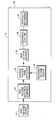
- the figure is an equipment cabinet 10 houses high voltage electrical equipment 12 which receives high voltage from a high voltage source 14. High voltage from the high voltage source 14 provides a source of energy for the equipment 12 to operate.
- the cabinet 10 also houses a residual voltage level detector 16 for monitoring residual voltage from the equipment 12 when high voltage applied to the equipment 12 is disconnected or removed. The voltage level of the residual voltage from the equipment 12 tends to decrease over time after high voltage applied to the equipment 12 is disconnected or removed.
- the cabinet 10 further houses an actuatable, high voltage solenoid 18 which has a plunger (not shown) mechanically coupled through a mechanical coupling 20 to an interlock mechanism 22 which, in turn, is mechanically coupled to a cover panel 24 of the cabinet 10.
- a plunger (not shown) mechanically coupled through a mechanical coupling 20 to an interlock mechanism 22 which, in turn, is mechanically coupled to a cover panel 24 of the cabinet 10.
- the solenoid 18 When the solenoid 18 is unactuated, the plunger is in a position such that the interlock mechanism 22 is in a locked position.
- the cover panel 24 cannot be opened or removed by service personnel to gain access to the equipment 12.
- the solenoid 18 actuates in response to an output signal from the residual voltage level detector 16.
- the residual voltage level detector 16 provides an output signal to actuate the high voltage solenoid 18 when the detector 16 senses that the voltage level of residual voltage from the equipment 12 decreases below a predetermined reference voltage level from a reference voltage source 19.
- the predetermined voltage level may be at any voltage level depending upon the particular application or the particular industry in which the equipment 12 is used, for examples.
- the plunger of the solenoid 18 operates through the mechanical coupling 20 to release the interlock mechanism 22.
- the interlock mechanism 22 moves from the locked position to an unlocked position such that the cover panel 24 can be opened or removed by service personnel to gain access to the equipment 12.
- a number of advantages result by providing an apparatus and method of controlling access to the equipment 12 in accordance with the present invention.
- One advantage is that the use of the residual voltage level detector 16 and the high voltage solenoid 18 allows the interlock mechanism 22 to be controlled such that the cover panel 24 is unable to be removed until residual voltage from the equipment 12 has decreased below the predetermined reference voltage level. This ensures that residual voltage from the equipment 12 has decreased below a certain voltage level before service personnel can open or remove the cover panel 24 to gain access to the equipment 12 to service the equipment 12.
- the above description describes the residual voltage level detector 16, the high voltage solenoid 18, the mechanical coupling 20, and the interlock mechanism 22 as being located inside the cabinet 10, it is contemplated that some or all of these parts may be located outside the cabinet 10. Further, although the above description describes a voltage level of residual voltage being sensed, it is contemplated that some other electrical quantity or characteristic, such as a current level associated with residual voltage, be sensed. It is conceivable that the high voltage solenoid 18 be deactuated, instead of actuated as described hereinabove, to release the interlock mechanism 22 to allow the cover panel 24 to be opened or removed. Moreover, it is contemplated that a door or the like may be used in place of or in conjunction with the cover panel 24.
Landscapes
- Engineering & Computer Science (AREA)
- Power Engineering (AREA)
- Patch Boards (AREA)
- Casings For Electric Apparatus (AREA)
Abstract
Description
Claims (10)
- An apparatus for controlling access to a service area of a cabinet in which equipment is disposed, the apparatus comprising:means for monitoring a residual electrical characteristic when high voltage applied to the equipment is removed; andmeans for releasing an interlock mechanism to allow access to the service area of the cabinet when the residual electrical characteristic decreases below a predetermined reference level.
- An apparatus according to claim 1, wherein the monitoring means includes means for monitoring a residual voltage, and the releasing means includes means for releasing an interlock mechanism when the residual voltage decreases below a predetermined voltage level.
- An apparatus comprising:a cabinet including means defining an opening and a panel which covers the opening;electrical equipment disposed in the cabinet and operable when high electrical energy is applied thereto;an interlock mechanism moveable between a locked position in which the panel covers the opening to prevent access to the electrical equipment and an unlocked position in which the panel can be opened or removed to allow access to the electrical equipment;reference means for providing a predetermined reference value;means for monitoring a residual electrical characteristic associated with the electrical equipment when high electrical is removed from the electrical equipment; andmeans for moving the interlock mechanism from the locked position to the unlocked position allow access to the electrical equipment when the residual electrical characteristic decreases below the predetermined reference value.
- An apparatus according to claim 3, wherein the panel comprises a door.
- An apparatus according to claim 3, wherein the reference means includes a reference voltage source for providing a predetermined reference voltage value.
- An apparatus according to claim 5, wherein the monitoring means includes a residual voltage level detector for monitoring a residual voltage associated with the electrical equipment.
- An apparatus according to claim 6, wherein the moving means includes an actuatable solenoid for, when actuated, moving the interlock mechanism from the locked position to the unlocked position allow access to the electrical equipment when the residual voltage associated with the electrical equipment decreases below the predetermined reference voltage value.
- A method of controlling access to a service area of a cabinet in which equipment is disposed, the method comprising the steps of:monitoring a residual electrical characteristic when high voltage applied to the equipment is removed; andreleasing an interlock mechanism to allow access to the service area of the cabinet when the residual electrical characteristic decreases below a predetermined reference level.
- A method according to claim 8, wherein the step of monitoring includes the step of monitoring a residual voltage, and the step of releasing includes the step of releasing an interlock mechanism when the residual voltage decreases below a predetermined voltage level.
- A method of servicing electrical equipment connectable to a high voltage source and disposed in a cabinet having an access opening and a panel which covers the access opening, the method comprising the steps of:monitoring a residual voltage associated with the electrical equipment when high voltage is removed from the electrical equipment; andmoving an interlock mechanism from a locked position in which the panel covers the opening to prevent access to the electrical equipment to an unlocked position in which the panel can be opened or removed to allow service personnel to access the electrical equipment when the residual voltage decreases below a predetermined voltage value.
Applications Claiming Priority (2)
| Application Number | Priority Date | Filing Date | Title |
|---|---|---|---|
| US206525 | 2002-07-26 | ||
| US10/206,525 US20040017643A1 (en) | 2002-07-26 | 2002-07-26 | Apparatus and method of controlling access to a service area of an equipment cabinet |
Publications (2)
| Publication Number | Publication Date |
|---|---|
| EP1394913A2 true EP1394913A2 (en) | 2004-03-03 |
| EP1394913A3 EP1394913A3 (en) | 2005-05-25 |
Family
ID=30770311
Family Applications (1)
| Application Number | Title | Priority Date | Filing Date |
|---|---|---|---|
| EP03253547A Withdrawn EP1394913A3 (en) | 2002-07-26 | 2003-06-04 | Apparatus and method of controlling access to a service area of an equipment cabinet |
Country Status (3)
| Country | Link |
|---|---|
| US (1) | US20040017643A1 (en) |
| EP (1) | EP1394913A3 (en) |
| JP (1) | JP2004064999A (en) |
Families Citing this family (5)
| Publication number | Priority date | Publication date | Assignee | Title |
|---|---|---|---|---|
| US7561412B2 (en) * | 2006-09-29 | 2009-07-14 | Rockwell Automation Technologies, Inc. | System and method for automatically securing a motor control center |
| DE102012204862A1 (en) | 2012-03-27 | 2013-10-02 | Robert Bosch Gmbh | Safety device for a high-voltage system and method for securing a high-voltage system |
| DE102018101510B4 (en) * | 2018-01-24 | 2024-12-05 | Dr. Ing. H.C. F. Porsche Aktiengesellschaft | traction battery charging arrangement |
| EP3671988A1 (en) * | 2018-12-19 | 2020-06-24 | ABB Schweiz AG | Hermetically sealed switchgear installation with single compartment for circuit breaker, three position disconnector and main bus bar. |
| US11774132B2 (en) | 2020-12-29 | 2023-10-03 | Trane International Inc. | Layered control panel design to provide separation of high/low voltage |
Family Cites Families (17)
| Publication number | Priority date | Publication date | Assignee | Title |
|---|---|---|---|---|
| US3573554A (en) * | 1969-07-01 | 1971-04-06 | Us Navy | Multiple power supply overvoltage and interlock controlled cutoff |
| US3864603A (en) * | 1973-11-12 | 1975-02-04 | Graco Inc | High voltage safety apparatus |
| US3882291A (en) * | 1974-02-14 | 1975-05-06 | Park Ohio Industries Inc | Mechanical interlock mechanism for an electrical cabinet |
| US4628396A (en) * | 1984-11-16 | 1986-12-09 | The United States Of America As Represented By The Secretary Of The Air Force | High voltage disconnect/reconnect switching device |
| DE3526013C1 (en) * | 1985-07-20 | 1986-10-23 | Ransburg Gmbh, 6056 Heusenstamm | Earthing system for coating booths |
| DE3709509A1 (en) * | 1987-03-23 | 1988-10-06 | Behr Industrieanlagen | Monitoring system for an electrostatic coating plant |
| US4980800A (en) * | 1989-09-27 | 1990-12-25 | Sun Microsystems, Inc. | Electronic unit retention system |
| JPH0771290B2 (en) * | 1989-12-27 | 1995-07-31 | 富士写真光機株式会社 | Signal processing circuit |
| US5099187A (en) * | 1990-03-21 | 1992-03-24 | California Institute Of Technology | Power connect safety and connection interlock |
| NL9201053A (en) * | 1992-06-15 | 1994-01-03 | Koninkl Philips Electronics Nv | SWITCHED CAPACITOR LOADING PUMP AND SAW Tooth Oscillator equipped with such a SWITCHED CAPACITOR LOADING PUMP. |
| US5424500A (en) * | 1994-04-08 | 1995-06-13 | Electro-Mechanical Corporation | Door-mounted operating mechanism for electrical switchgear |
| US5955795A (en) * | 1996-10-28 | 1999-09-21 | Beer; David W. | Apparatus for enclosing appliances |
| DE19808271C1 (en) * | 1998-02-27 | 1999-09-30 | Loh Kg Rittal Werk | Lock for a control cabinet door or machine cladding |
| DE19816140A1 (en) * | 1998-04-09 | 1999-10-14 | Schnier Elektrostatik Gmbh | Method and circuit arrangement for the security check of a high-voltage supply system |
| DE19911320A1 (en) * | 1999-03-13 | 2000-09-21 | Loh Kg Rittal Werk | Monitoring device for switch box with operation restricted to monitoring of preset threshold values |
| DE19915374A1 (en) * | 1999-04-06 | 2000-10-12 | Schnier Elektrostatik Gmbh | Method and circuit arrangement for the safety check of an electrostatic spraying system |
| US6689968B2 (en) * | 2001-12-18 | 2004-02-10 | Abb Technology Ag | Circuit breaker with capacitor discharge system |
-
2002
- 2002-07-26 US US10/206,525 patent/US20040017643A1/en not_active Abandoned
-
2003
- 2003-06-04 EP EP03253547A patent/EP1394913A3/en not_active Withdrawn
- 2003-07-25 JP JP2003279883A patent/JP2004064999A/en active Pending
Also Published As
| Publication number | Publication date |
|---|---|
| US20040017643A1 (en) | 2004-01-29 |
| JP2004064999A (en) | 2004-02-26 |
| EP1394913A3 (en) | 2005-05-25 |
Similar Documents
| Publication | Publication Date | Title |
|---|---|---|
| FI90274B (en) | Device in the door lock case | |
| EP2518747B1 (en) | Emergency stop, emergency stop terminal, use of a display in an emergency stop and method for operating an emergency stop | |
| US8814233B2 (en) | Safety switch for generating a system enable signal depending on the position of a movable guard door | |
| CN110800178B (en) | Medium-high voltage substation of unmanned operation and maintenance switch equipment or control equipment | |
| US7973253B2 (en) | Neutral draw-out automatic transfer switch assembly and associated method | |
| US4115952A (en) | Safety door edge | |
| US5424911A (en) | Compact motor controller assembly | |
| WO2004109236A1 (en) | Sensor for the detection of the position of a mechanical force-transmitting device | |
| EP0774556A3 (en) | Combination lock | |
| US20180132368A1 (en) | Access device housing with deployable cover for user interface | |
| WO2003087510A3 (en) | A balance control system for a movable barrier operator | |
| US20040017643A1 (en) | Apparatus and method of controlling access to a service area of an equipment cabinet | |
| US11784470B2 (en) | Enhanced energy reducing maintenance switch (EERMS) to reduce electric arc flash energy | |
| EP1849951B1 (en) | Sliding door assembly | |
| GB2290181A (en) | Circuit breaker lockout accessory | |
| EP2197776B1 (en) | Safety lock | |
| US20080253541A1 (en) | Fluid-operated communication system | |
| DE19911320A1 (en) | Monitoring device for switch box with operation restricted to monitoring of preset threshold values | |
| EP1138450A2 (en) | Industrial robot and method of operating same | |
| EP0082169B1 (en) | Safety mechanism for preventing the locking up of persons in cabinets | |
| US5844186A (en) | Motor contractor with mechanical lock-out | |
| SE518546C2 (en) | End plate for doors | |
| EP2571121A1 (en) | Withdrawable unit with rotating electrical contacts | |
| AU2003244561B2 (en) | Merchandise container | |
| US20150130566A1 (en) | Means for providing improved operation properties for electrically operated circuit breakers, disconnect switches, and contactors |
Legal Events
| Date | Code | Title | Description |
|---|---|---|---|
| PUAI | Public reference made under article 153(3) epc to a published international application that has entered the european phase |
Free format text: ORIGINAL CODE: 0009012 |
|
| AK | Designated contracting states |
Kind code of ref document: A2 Designated state(s): AT BE BG CH CY CZ DE DK EE ES FI FR GB GR HU IE IT LI LU MC NL PT RO SE SI SK TR |
|
| AX | Request for extension of the european patent |
Extension state: AL LT LV MK |
|
| PUAL | Search report despatched |
Free format text: ORIGINAL CODE: 0009013 |
|
| AK | Designated contracting states |
Kind code of ref document: A3 Designated state(s): AT BE BG CH CY CZ DE DK EE ES FI FR GB GR HU IE IT LI LU MC NL PT RO SE SI SK TR |
|
| AX | Request for extension of the european patent |
Extension state: AL LT LV MK |
|
| RIC1 | Information provided on ipc code assigned before grant |
Ipc: 7B 05B 5/10 B Ipc: 7H 02B 1/38 B Ipc: 7H 02B 1/06 A |
|
| 17P | Request for examination filed |
Effective date: 20051125 |
|
| AKX | Designation fees paid |
Designated state(s): DE ES FR GB IT |
|
| STAA | Information on the status of an ep patent application or granted ep patent |
Free format text: STATUS: THE APPLICATION IS DEEMED TO BE WITHDRAWN |
|
| 18D | Application deemed to be withdrawn |
Effective date: 20070101 |