EP1394836A1 - Cold spray mass spectrometric device - Google Patents
Cold spray mass spectrometric device Download PDFInfo
- Publication number
- EP1394836A1 EP1394836A1 EP02738622A EP02738622A EP1394836A1 EP 1394836 A1 EP1394836 A1 EP 1394836A1 EP 02738622 A EP02738622 A EP 02738622A EP 02738622 A EP02738622 A EP 02738622A EP 1394836 A1 EP1394836 A1 EP 1394836A1
- Authority
- EP
- European Patent Office
- Prior art keywords
- block
- desolvation
- coldspray
- mass spectrometer
- temperature
- Prior art date
- Legal status (The legal status is an assumption and is not a legal conclusion. Google has not performed a legal analysis and makes no representation as to the accuracy of the status listed.)
- Granted
Links
Images

Classifications
-
- H—ELECTRICITY
- H01—ELECTRIC ELEMENTS
- H01J—ELECTRIC DISCHARGE TUBES OR DISCHARGE LAMPS
- H01J49/00—Particle spectrometers or separator tubes
- H01J49/02—Details
- H01J49/04—Arrangements for introducing or extracting samples to be analysed, e.g. vacuum locks; Arrangements for external adjustment of electron- or ion-optical components
- H01J49/0468—Arrangements for introducing or extracting samples to be analysed, e.g. vacuum locks; Arrangements for external adjustment of electron- or ion-optical components with means for heating or cooling the sample
-
- B—PERFORMING OPERATIONS; TRANSPORTING
- B05—SPRAYING OR ATOMISING IN GENERAL; APPLYING FLUENT MATERIALS TO SURFACES, IN GENERAL
- B05B—SPRAYING APPARATUS; ATOMISING APPARATUS; NOZZLES
- B05B5/00—Electrostatic spraying apparatus; Spraying apparatus with means for charging the spray electrically; Apparatus for spraying liquids or other fluent materials by other electric means
- B05B5/001—Electrostatic spraying apparatus; Spraying apparatus with means for charging the spray electrically; Apparatus for spraying liquids or other fluent materials by other electric means incorporating means for heating or cooling, e.g. the material to be sprayed
-
- H—ELECTRICITY
- H01—ELECTRIC ELEMENTS
- H01J—ELECTRIC DISCHARGE TUBES OR DISCHARGE LAMPS
- H01J49/00—Particle spectrometers or separator tubes
- H01J49/02—Details
- H01J49/04—Arrangements for introducing or extracting samples to be analysed, e.g. vacuum locks; Arrangements for external adjustment of electron- or ion-optical components
- H01J49/0431—Arrangements for introducing or extracting samples to be analysed, e.g. vacuum locks; Arrangements for external adjustment of electron- or ion-optical components for liquid samples
- H01J49/044—Arrangements for introducing or extracting samples to be analysed, e.g. vacuum locks; Arrangements for external adjustment of electron- or ion-optical components for liquid samples with means for preventing droplets from entering the analyzer; Desolvation of droplets
-
- H—ELECTRICITY
- H01—ELECTRIC ELEMENTS
- H01J—ELECTRIC DISCHARGE TUBES OR DISCHARGE LAMPS
- H01J49/00—Particle spectrometers or separator tubes
- H01J49/02—Details
- H01J49/10—Ion sources; Ion guns
- H01J49/16—Ion sources; Ion guns using surface ionisation, e.g. field-, thermionic- or photo-emission
- H01J49/165—Electrospray ionisation
-
- B—PERFORMING OPERATIONS; TRANSPORTING
- B05—SPRAYING OR ATOMISING IN GENERAL; APPLYING FLUENT MATERIALS TO SURFACES, IN GENERAL
- B05B—SPRAYING APPARATUS; ATOMISING APPARATUS; NOZZLES
- B05B5/00—Electrostatic spraying apparatus; Spraying apparatus with means for charging the spray electrically; Apparatus for spraying liquids or other fluent materials by other electric means
- B05B5/025—Discharge apparatus, e.g. electrostatic spray guns
- B05B5/0255—Discharge apparatus, e.g. electrostatic spray guns spraying and depositing by electrostatic forces only
Definitions
- the present invention relates to a mass spectrometer and, more particularly, to a coldspray mass spectrometer capable of ionizing samples at low temperatures.
- electrospray When an electrically conducting liquid is placed within a strong electric field, the liquid spontaneously sprays out of the tip of a capillary tube by the action of the field. This phenomenon is termed electrospray and has been known for many years. The electrospray phenomenon was applied to mass spectrometry of samples in solution form in the former half of 1980s and has come to be widely used in electrospray mass spectrometers.
- a high voltage of several kilovolts is applied between the capillary 32 and the counter electrode 34 of the mass spectrometer 33 to produce a strong electric field.
- the solution sample in the capillary 32 is electrostatically sprayed into the space between the capillary 32 and the counter electrode 34 under atmospheric pressure and disperses into the air as charged liquid droplets.
- the flow rate of the solution sample is 1 to 10 microliters per minute. Since the produced charged liquid droplets are clusters formed by solvent molecules collected around sample molecules, only ions of the sample molecules can be left if heat is applied to evaporate off the solvent molecules.
- One method of creating sample ions from charged liquid droplets consists of heating nitrogen gas to about 70°C, supplying the hot gas into the space between the capillary 32 and the counter electrode 34, and electrostatically spraying the droplets into the space to evaporate off the solvent of the liquid droplets.
- Another method consists of heating a sampling orifice 35 formed in the counter electrode 34 of the mass spectrometer 33 to about 80°C and evaporating off the solvent of the liquid droplets by the resulting radiative heat or thermal conduction. These methods are known as ion evaporation.
- Sample ions created by ion evaporation are accepted into the mass spectrometer 33 through the sampling orifice 35 formed in the counter electrode 34.
- differentially pumped walls are formed.
- a partition surrounded by the sampling orifice 35 and a skimmer orifice 36 is evacuated to about 200 Pa by a rotary pump (RP) (not shown).
- RP rotary pump
- apartition surrounded by the skimmer orifice 36 and a partition wall 37 is evacuated to about 1 Pa by a turbomolecular pump (TMP) (not shown).
- TMP turbomolecular pump
- the stage located behind the partition wall 37 is evacuated to about 10 -3 Pa by the TMP, and a mass analyzer 38 is placed in this stage.
- a ring lens 39 is placed in a low-vacuum partition surrounded by the sampling orifice 35 and the skimmer orifice 36.
- a voltage that is positive or negative is applied to the ring lens 39, depending on whether the sample ions are positive or negative, respectively, to prevent diffusion of the sample ions.
- An ion guide 40 to which an RF voltage is applied is placed in a moderate-vacuum partition surrounded by the skimmer orifice 36 and the partition wall 37 to guide sample ions into the mass analyzer 38.
- a sheath tube (not shown in Fig. 1) through which a nebulizing gas can flow is mounted around the capillary 32, thus coping with a high flow rate of sample such as 10 to 1000 microliters/min as encountered with an LC mobile phase.
- a high flow rate of solution sample more than 10 microliters/min that cannot be fully nebulized by electric field force alone can be fully nebulized by the force of the nebulizing gas.
- An electrospray ion source is characterized in that it provides a very soft ionization method which utilizes neither application of high temperature nor bombardment of high-energy particles in ionizing sample molecules. Therefore, highly polar biomolecular polymers such as peptide, proteins, and nucleic acids can be readily ionized into polyvalent ions almost nondestructively. Furthermore, since they are polyvalent ions, they can be investigated with a relatively small-sized mass spectrometer even if the molecular weight is in excess of ten thousands.
- a new type of electrospray mass spectrometer has been developed (Japanese patent laid-open No. 2000-285847).
- a nebulizing gas supplied into an electrospray ion source and a desolvation chamber for charged particle droplets are cooled by a refrigerant such as liquid nitrogen to minimize the heat applied to sample ions during ionization.
- This cooling device promotes electrolytic dissociation to form molecular ions base on increasing polarizability of the compounds and/or solventmolecules caused by the higher dielectic constant at low temperature.
- This method is known as coldspray ionization, and has first succeeded in accurately measuring the mass numbers of unstable self-assembling organic-metal complexes as mentioned previously by directly spraying liquid nitrogen against the desolvation chamber, as shown in Fig. 2.
- the feature of such a coldspray mass spectrometer is that the nebulizing gas and desolvation chamber are cooled by a refrigerant such as liquid nitrogen to minimize the application of heat to charged liquid droplets.
- a refrigerant such as liquid nitrogen
- the desolvation chamber is directly cooled by liquid nitrogen and so overcooling occurs. This makes it difficult to set the desolvation chamber to a temperature range best adapted for measurements. It takes a long time until the instrument stabilizes.
- the cooling gas for cooling the desolvation chamber directly flows into the ionization chamber, thus disturbing the air flow in the chamber. Consequently, it is difficult to stabilize the ion beam.
- the present invention has been made. It is an object of the present invention to provide a coldspray mass spectrometer which is easy to handle, is capable of preventing condensation of water and electrical leakage for a long time, and has a desolvation block whose temperature can be easily controlled, thus permitting stable measurements.
- a coldspray mass spectrometer built in accordance with the present invention, the spectrometer being designed to perform a mass analysis by spraying a solution sample at a low temperature and desolvating the sample, the spectrometer comprising (a) a needle pipe through which the solution sample is passed, (b) a sheath tube which is formed coaxially with the needle pipe and through which a temperature-controlled nebulizing gas is passed, (c) a desolvation block having a passageway extending from the tip of the needle pipe, the passageway permitting passage of charged liquid droplets of the solution sample, the desolvation block acting to remove solvent from the charged liquid droplets passing through the passageway, (d) cooling means for cooling the desolvation block, (e) heating means for heating the desolvation block, and (f) a temperature sensor for detecting the temperature of the desolvationblock.
- the desolvationblock canbe controlled to any desired temperature.
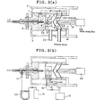
- Figs. 3 (a) and 3 (b) there is shown a coldspray mass spectrometer according to one embodiment of the present invention.
- Fig. 3 (a) is a top plan view of the mass spectrometer.
- Fig. 3 (b) is a side elevation of the instrument.
- This spectrometer has an ionization chamber 1 including a needle pipe 8 and a desolvation block 3.
- a high voltage is applied to the needle pipe 8 to electrostatically spray a solution sample.
- the desolvation block 3 is used to desolvate charged liquid droplets electrostatically sprayed from the tip of the needle pipe 8.
- the needle pipe 8 incorporates a sheath tube 24 mounted coaxially with the needle pipe 8, thus forming a double tube.
- a nebulizing gas that helps electrostatic spraying flows through the sheath tube 24.
- a heater 4 for heating the desolvation block 3 and a temperature sensor 5 for detecting the temperature of the desolvation block 3 are buried in the wall of
- the desolvation block 3 is provided with a heating passage hole 10 to desolvate the charged liquid droplets at a high temperature.
- the block 3 is also provided with a cooling passage hole 11 to desolvate the liquid droplets at a low temperature.
- the position of the tip of the needle pipe 8 can be switched between a position on the side of the entrance of the heating passage hole 10 and a position on the side of the entrance of the cooling passage hole 11 by a position-adjusting knob 9, to permit the user to select between normal electrospray ionization and coldspray ionization.
- a bypass rod 26 is mounted in the cooling passage hole 11 to bypass the charged liquid droplets; otherwise, the electrostatically sprayed liquid droplets would immediately reach the first orifice 6.
- differentially pumped walls are formed.
- a partition surrounded by the first orifice 6 and the second orifice 7 is evacuated to about 200 Pa by a rotary pump (RP) (not shown).
- a partition surrounded by the second orifice 7 and a partition wall (not shown) is evacuated to about 1 Pa by a turbomolecular pump (TMP) (not shown).
- TMP turbomolecular pump
- a stage (not shown) locatedbehindthispartitionwall (not shown) is evacuated to about 10 -3 Pa by the TMP, and a mass analyzer (not shown) is placed in this stage.
- the sample desolvated by the desolvation block 3 and turned into ions is accepted into the mass spectrometer from the first orifice 6.
- a ring lens 23 is placed in the low-vacuum partition surrounded by the first orifice 6 and the second orifice 7 to prevent diffusion of the sample ions.
- a voltage that is positive or negative is applied to the ring lens 23, depending on whether the sample ions are positive or negative, respectively, to prevent diffusion of the sample ions.
- An ion guide 21 is placed in a moderate-vacuum partition surrounded by the second orifice 7 and a partition wall (not shown) to guide the sample ions into the mass analyzer 38.
- An RF voltage is applied to the ion guide 21.
- nebulizing nitrogen gas 17 supplied from a nitrogen bottle 18 is cooled to about -20°C by a refrigerator jar 20 and then ejected from the sheath tube 24.
- Cooling nitrogen gas 15 supplied from a liquid nitrogen jar 19 is blown directly against the wall of the desolvation block 3 through an insulating pipe 12 to lower the temperature of the desolvation block 3.
- control is provided such that no heat is applied to the charged liquid droplets of the sample.
- the position of the tip of the needle pipe 8 is aligned to the cooling passage hole 11 by the position-adjusting knob 9.
- the charged liquid droplets pass through the cooling passage hole 11 and thus are desolvated.
- the heater 4 may be appropriately operated while cooling the block by the cooling nitrogen gas 15.
- nebulizing nitrogen gas 17 supplied from the nitrogen bottle 18 is ejected from the sheath tube 24 while maintaining the gas at room temperature.
- Supply of the cooling nitrogen gas 15 from the liquid nitrogen jar 19 is cut off.
- the desolvation block 3 is heated to 100-300°C by the heater 4.
- control is provided such that heat is applied to the charged liquid droplets of the sample.
- the position of the tip of the needle pipe 8 is aligned to the heating passage hole 10 by the position-adjusting knob 9.
- the droplets pass through the heating passage hole 10.
- the mode of operation can be switched arbitrarily between the coldspray ionization mode and the normal electrospray ionization mode.
- a second chamber 2 surrounded by a case 13 is formed around the ionization chamber 1.
- Wires for a high-voltage source for applying high voltages to the needle pipe 8, the first orifice 6, the second orifice 7, and so on are held in this chamber 2.
- wire connectors 14 for the heater 4 and temperature sensor 5 are held in the second chamber 2. Dry purge gas is kept supplied into this chamber 2 from a gas source (not shown) to prevent introduction of moisture from the outside; otherwise, dewing would occur when the desolvation block 3 is cooled.
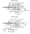
- Figs. 4(a) and 4(b) show another coldspray mass spectrometer according to the invention.
- Fig. 4(a) is a top plan view of the instrument.
- Fig. 4(b) is a side elevation of the instrument.
- This mass spectrometer has an ionization chamber 1 containing a needle pipe 8 and a desolvation block 3.
- a high voltage is applied to the needle pipe 8 to electrostatically spray a solution sample.
- the desolvation block 3 is used to desolvate charged liquid droplets electrostatically sprayed from the tip of the needle pipe 8.
- a sheath tube 24 for conveying a nebulizing gas that assists electrostatic spraying is mounted coaxially inside the needle pipe 8. Thus, a double tube is formed.
- a heater 4 for heating the desolvation block 3 and a temperature sensor 5 for detecting the temperature of the block 3 are buried in the wall of the desolvation block 3.
- the desolvation block 3 is formed with a heating passage hole 10 for desolvating the charged liquid droplets at a high temperature.
- the block 3 is also provided with a cooling passage hole 11 for desolvating the charged liquid droplets at a low temperature.
- the position of the tip of the needle pipe 8 can be switched between the entrance side of the heating passage hole 10 and the entrance side of the cooling passage hole 11 by the position-adjusting knob 9. This permits one to select between the normal electrospray ionization and the coldspray ionization.
- a bypass rod 26 is mounted in the cooling passage hole 11 to bypass the charged liquid droplets; otherwise, the electrostatically sprayed liquid droplets would immediately reach the first orifice 6.
- differentially pumped walls are formed.
- a partition surrounded by a first orifice 6 and a second orifice 7 is evacuated to about 200 Pa by a rotary pump (RP) (not shown).
- a partition surrounded by the second orifice 7 and a partition wall (not shown) is evacuated to about 1 Pa by a turbomolecular pump (TMP) (not shown).
- TMP turbomolecular pump
- the stage located behind the partition wall (not shown) is evacuated to about 10 -3 Pa by the TMP, and a mass analyzer (not shown) is placed in this stage.
- the sample desolvated by the desolvation block 3 and turned into ions is accepted into the mass spectrometer from the first orifice 6.
- a ring lens 23 is placed in the low-vacuum partition surrounded by the first orifice 6 and the second orifice 7.
- a voltage that is positive or negative is applied to the ring lens 23, depending on whether the sample ions are positive or negative, respectively, to prevent diffusion of the sample ions.
- An ion guide 21 is placed in a moderate-vacuum partition surrounded by the second orifice 7 and the partition wall (not shown) to guide the sample ions into the mass analyzer 38.
- An RF voltage is applied to the ion guide 21.
- nebulizing nitrogen gas 17 supplied from a nitrogen bottle 18 and cooling nitrogen gas 15 are cooled to about -20°C by a common refrigerator jar 20 and then supplied into the sheath tube 24 and into a refrigerant passage 25 formed in the wall of the desolvation block 3, thus cooling the needle pipe 8 and the desolvation block 3 at the same time. Therefore, in the present embodiment, the cooling nitrogen gas 15 flows in the refrigerant passage 25. Consequently, the gas flow in the ionization chamber 1 is less disturbed compared with the method consisting of directly blowing liquid nitrogen against the desolvation block 3. Hence, an ion beam can be supplied stably.
- a heater 4 may be appropriately operated while cooling the block by the cooling nitrogen gas 15.
- nebulizing nitrogen gas 17 supplied from the nitrogen bottle 18 is ejected from the sheath tube 24 while maintaining the gas at room temperature.
- Supply of the cooling nitrogen gas 15 from the liquid nitrogen jar 19 is cut off.
- the desolvation block 3 is heated to 100-300°C by the heater 4.
- control is provided such that heat is applied to the charged liquid droplets of the sample.
- the position of the tip of the needle pipe 8 is aligned to the heating passage hole 10 by the position-adjusting knob 9.
- the droplets pass through the heating passage hole 10.
- the mode of operation can be switched arbitrarily between the coldspray ionization mode and normal electrospray ionization mode.
- a second chamber 2 surrounded by a case 13 is formed around the ionization chamber 1.
- Wires for a high-voltage source for applying high voltages to the needle pipe 8, the first orifice 6, the second orifice 7, and so on are held in this chamber 2.
- wire connectors 14 for the heater 4 and temperature sensor 5 are held in the second chamber 2.
- the cooling dry nitrogen gas 15 flowing through a refrigerant passage 25 formed in the wall of the desolvation block 3 is admitted into, and circulated through, the second chamber 2 via a cooling gas exit 16.
- the inside of the second chamber 2 is purged by making effective use of the used dry nitrogen gas 15 for cooling.
- cheap nitrogen gas is used as a cooling gas.
- Inert gases other than nitrogen gas may also be used.
- the dry gas introduced in the second chamber of the second embodiment is not always a used cooling gas.
- a separate gas source may be provided.
- the cooling gas may also be cooled by a cooling means other than a refrigerator, e.g., a dry ice bath consisting of a combination of dry ice and an organic solvent.
- the refrigerant passage 25 is not always required to be formed in the wall of the desolvation block 3.
- the passage may be formed anywhere near the desolvation block 3 as long as effective cooling of the block 3 is achieved.
- the refrigerant for cooling the desolvation block 3 is not always an expendable gas.
- a temperature-controlled fluid may be circulated in use.
- the above-described nebulizing gas may be used as the means for cooling the desolvation block described above.
- the cooling nitrogen gas 15 does not need to be sprayed against the block wall in the embodiment described in connection with Fig. 3.
- the coldspray mass spectrometer comprises means for cooling and/or heating the desolvation block and a temperature sensor for detecting the temperature of the desolvation block.
- the second chamber 2 where electrical wires are accommodated is purged with a dry gas and so it is easy to control the temperature of the desolvation block 3. Furthermore, water condensation and electrical leakage can be prevented for a long time.
- the coldspray mass spectrometer can perform measurements stably and is easy to handle.
Landscapes
- Chemical & Material Sciences (AREA)
- Analytical Chemistry (AREA)
- Physics & Mathematics (AREA)
- Engineering & Computer Science (AREA)
- Plasma & Fusion (AREA)
- Electron Tubes For Measurement (AREA)
- Other Investigation Or Analysis Of Materials By Electrical Means (AREA)
Abstract
Description
Claims (9)
- A coldspray mass spectrometer for performing a mass analysis by spraying a solution sample at a low temperature and desolvating the sample, said coldspray mass spectrometer comprising:wherein said desolvation block can be controlled to any desired temperature.(a) a needle pipe through which the solution sample is passed;(b) a sheath tube which is formed coaxially with the needle pipe and through which a temperature-controlled nebulizing gas is passed;(c) a desolvation block having a passageway extending from a tip of the needle pipe, the passageway permitting passage of charged liquid droplets of the solution sample, the desolvation block acting to remove a solvent from the charged liquid droplets passing through the passageway;(d) cooling means for cooling the desolvation block;(e) heating means for heating the desolvation block; and(f) a temperature sensor for detecting the temperature of the desolvation block;
- A coldspray mass spectrometer for performing a mass analysis by spraying a solution sample at a low temperature and desolvating the sample, said coldspray mass spectrometer comprising:wherein mode of operation of the mass spectrometer can be switched between coldspray ionization mode and normal electrospray ionization mode.(a) a needle pipe through which the solution sample is passed;(b) a sheath tube which is formed coaxially with the needle pipe and through which a temperature-controlled nebulizing gas is passed;(c) a desolvation block having a passageway extending from a tip of the needle pipe, the passageway permitting passage of charged liquid droplets of the solution sample, the desolvation block acting to remove a solvent from the charged liquid droplets passing through the passageway;(d) cooling means for cooling the desolvation block;(e) heating means for heating the desolvation block; and(f) a temperature sensor for detecting the temperature of the desolvation block;
- A coldspray mass spectrometer as set forth in any one of claims 1 and 2, wherein said desolvation block has a heating passage for desolvating said charged liquid droplets at a high temperature and a cooling passage for desolvating said charged liquid droplets at a low temperature, and wherein a passage for said charged liquid droplets can be selected between said heating passage and said cooling passage.
- A coldspray mass spectrometer as set forth in claim 3, wherein any one of said heating passage and said cooling passage is selected by moving said needle pipe.
- A coldspray mass spectrometer as set forth in any one of claims 1 and 2, wherein a refrigerant passage is formed in said desolvation block, and wherein a refrigerant is passed through said refrigerant passage to thereby cool said desolvation block.
- A coldspray mass spectrometer as set forth in any one of claims 1 and 2, wherein the temperature-controlled nebulizing gas supplied into the sheath tube and a refrigerant supplied into said means for cooling the desolvation block are supplied from a common refrigerator.
- A coldspray mass spectrometer as set forth in any one of claims 1 and 2, wherein a space for accommodating an electrical circuit for controlling a coldspray ion source is formed separately from an ionization chamber in which said desolvation block is placed.
- A coldspray mass spectrometer as set forth in claim 7, wherein a refrigerant already used to cool the desolvation block is discharged to the outside through said space.
- A coldspray mass spectrometer as set forth in claim 7, further comprising a gas source for supplying a dry gas into said space
Applications Claiming Priority (3)
| Application Number | Priority Date | Filing Date | Title |
|---|---|---|---|
| JP2001174265 | 2001-06-08 | ||
| JP2001174265 | 2001-06-08 | ||
| PCT/JP2002/005540 WO2002101788A1 (en) | 2001-06-08 | 2002-06-05 | Cold spray mass spectrometric device |
Publications (3)
| Publication Number | Publication Date |
|---|---|
| EP1394836A1 true EP1394836A1 (en) | 2004-03-03 |
| EP1394836A4 EP1394836A4 (en) | 2007-06-27 |
| EP1394836B1 EP1394836B1 (en) | 2011-09-21 |
Family
ID=19015574
Family Applications (1)
| Application Number | Title | Priority Date | Filing Date |
|---|---|---|---|
| EP02738622A Expired - Lifetime EP1394836B1 (en) | 2001-06-08 | 2002-06-05 | Cold spray mass spectrometric device |
Country Status (4)
| Country | Link |
|---|---|
| US (1) | US6977369B2 (en) |
| EP (1) | EP1394836B1 (en) |
| JP (1) | JP3786417B2 (en) |
| WO (1) | WO2002101788A1 (en) |
Cited By (2)
| Publication number | Priority date | Publication date | Assignee | Title |
|---|---|---|---|---|
| CN102903596A (en) * | 2012-09-18 | 2013-01-30 | 清华大学 | Ion source temperature control heating device |
| CN111880589A (en) * | 2020-09-02 | 2020-11-03 | 江苏天瑞仪器股份有限公司 | A light chamber hybrid heating and cooling constant temperature system |
Families Citing this family (33)
| Publication number | Priority date | Publication date | Assignee | Title |
|---|---|---|---|---|
| JP4133631B2 (en) * | 2002-08-19 | 2008-08-13 | 日本電子株式会社 | Electrospray mass spectrometer |
| JP4174599B2 (en) * | 2003-07-08 | 2008-11-05 | 株式会社島津製作所 | High-performance liquid chromatograph fractionator |
| JP4207782B2 (en) * | 2004-01-06 | 2009-01-14 | 株式会社島津製作所 | Liquid chromatograph fractionator |
| JP4148143B2 (en) * | 2004-01-19 | 2008-09-10 | 株式会社島津製作所 | Fractionation device such as liquid chromatograph |
| CN100582768C (en) * | 2004-05-18 | 2010-01-20 | 国立大学法人山梨大学 | Method and device for selectively cleaving non-covalent bonds of biological macromolecules and analyzing them |
| WO2009066358A1 (en) * | 2007-11-22 | 2009-05-28 | Shimadzu Corporation | Mass spectrometer |
| US20100154568A1 (en) * | 2008-11-19 | 2010-06-24 | Roth Michael J | Analytical Instruments, Assemblies, and Methods |
| US20100224695A1 (en) * | 2009-03-08 | 2010-09-09 | Excellims Corporation | Controlling ionization source temperature |
| FR2953927B1 (en) * | 2009-12-14 | 2012-02-03 | Commissariat Energie Atomique | DEVICE AND METHOD FOR MANUFACTURING SAMPLE FROM A LIQUID |
| EP2660590A1 (en) * | 2010-12-27 | 2013-11-06 | Shiseido Co., Ltd. | Mass spectrometry method, mass spectrometer, and mass spectrometry system |
| US20120228490A1 (en) * | 2011-03-13 | 2012-09-13 | Excellims Corporation | Apparatus and method for ion mobility spectrometry and sample introduction |
| JP6182705B2 (en) * | 2011-06-03 | 2017-08-23 | パーキンエルマー ヘルス サイエンス インコーポレイテッドPerkinelmer Health Sciences Inc. | Ion source for direct sample analysis |
| GB201208812D0 (en) * | 2012-05-18 | 2012-07-04 | Micromass Ltd | Cryogenic collision cell |
| JP6433982B2 (en) * | 2013-04-19 | 2018-12-05 | シーメンス・ヘルスケア・ダイアグノスティックス・インコーポレーテッドSiemens Healthcare Diagnostics Inc. | Contactless microdrop dispenser and method |
| EP3084422A4 (en) * | 2013-12-20 | 2017-08-02 | DH Technologies Development PTE. Ltd. | Ion source for mass spectrometry |
| US9230786B1 (en) | 2014-06-11 | 2016-01-05 | Bruker Daltonics, Inc. | Off-axis channel in electrospray ionization for removal of particulate matter |
| CN104807876B (en) * | 2015-05-27 | 2017-03-15 | 中国工程物理研究院材料研究所 | Electro spraying ionization-mass spectrometry system and its using method for radioactive substance |
| US10226791B2 (en) | 2017-01-13 | 2019-03-12 | United Technologies Corporation | Cold spray system with variable tailored feedstock cartridges |
| CN110446921A (en) * | 2017-03-16 | 2019-11-12 | 株式会社岛津制作所 | The supply control method and device of charged particle |
| GB201808912D0 (en) | 2018-05-31 | 2018-07-18 | Micromass Ltd | Bench-top time of flight mass spectrometer |
| WO2019229463A1 (en) | 2018-05-31 | 2019-12-05 | Micromass Uk Limited | Mass spectrometer having fragmentation region |
| GB201808949D0 (en) * | 2018-05-31 | 2018-07-18 | Micromass Ltd | Bench-top time of flight mass spectrometer |
| GB201808892D0 (en) | 2018-05-31 | 2018-07-18 | Micromass Ltd | Mass spectrometer |
| GB201808894D0 (en) | 2018-05-31 | 2018-07-18 | Micromass Ltd | Mass spectrometer |
| GB201808890D0 (en) | 2018-05-31 | 2018-07-18 | Micromass Ltd | Bench-top time of flight mass spectrometer |
| GB201808893D0 (en) | 2018-05-31 | 2018-07-18 | Micromass Ltd | Bench-top time of flight mass spectrometer |
| WO2019229469A1 (en) | 2018-05-31 | 2019-12-05 | Micromass Uk Limited | Mass spectrometer |
| GB201808932D0 (en) | 2018-05-31 | 2018-07-18 | Micromass Ltd | Bench-top time of flight mass spectrometer |
| GB201808936D0 (en) | 2018-05-31 | 2018-07-18 | Micromass Ltd | Bench-top time of flight mass spectrometer |
| CN112599404B (en) * | 2020-12-10 | 2022-10-18 | 中国科学院深圳先进技术研究院 | A low-temperature desorption electrospray ionization device and method for mass spectrometry imaging |
| CN112670154B (en) * | 2020-12-28 | 2025-04-29 | 广州禾信仪器股份有限公司 | Flexible ionization device for metal-organic complexes |
| CN115382712B (en) * | 2021-05-08 | 2023-12-12 | 中国科学院化学研究所 | MALDI mass spectrum matrix spraying instrument and spraying method |
| CN115301466B (en) * | 2022-07-12 | 2024-03-22 | 天津国科医工科技发展有限公司 | Modularized mass spectrum matrix spraying device and method |
Family Cites Families (5)
| Publication number | Priority date | Publication date | Assignee | Title |
|---|---|---|---|---|
| JP2790927B2 (en) | 1991-10-03 | 1998-08-27 | 株式会社日立製作所 | Liquid chromatograph mass spectrometer |
| WO1997029508A2 (en) * | 1996-02-08 | 1997-08-14 | Perseptive Biosystems, Inc. | Interface between liquid flow and mass spectrometer |
| JP3388102B2 (en) | 1996-08-09 | 2003-03-17 | 日本電子株式会社 | Ion source |
| JP3137953B2 (en) | 1999-03-30 | 2001-02-26 | 科学技術振興事業団 | Electrospray mass spectrometry method and apparatus |
| US7015466B2 (en) * | 2003-07-24 | 2006-03-21 | Purdue Research Foundation | Electrosonic spray ionization method and device for the atmospheric ionization of molecules |
-
2002
- 2002-06-05 JP JP2003504438A patent/JP3786417B2/en not_active Expired - Lifetime
- 2002-06-05 WO PCT/JP2002/005540 patent/WO2002101788A1/en not_active Ceased
- 2002-06-05 EP EP02738622A patent/EP1394836B1/en not_active Expired - Lifetime
- 2002-06-05 US US10/343,329 patent/US6977369B2/en not_active Expired - Lifetime
Cited By (3)
| Publication number | Priority date | Publication date | Assignee | Title |
|---|---|---|---|---|
| CN102903596A (en) * | 2012-09-18 | 2013-01-30 | 清华大学 | Ion source temperature control heating device |
| CN102903596B (en) * | 2012-09-18 | 2015-08-12 | 清华大学 | A kind of ion source temperature control heating device |
| CN111880589A (en) * | 2020-09-02 | 2020-11-03 | 江苏天瑞仪器股份有限公司 | A light chamber hybrid heating and cooling constant temperature system |
Also Published As
| Publication number | Publication date |
|---|---|
| WO2002101788A1 (en) | 2002-12-19 |
| US6977369B2 (en) | 2005-12-20 |
| JP3786417B2 (en) | 2006-06-14 |
| US20030168586A1 (en) | 2003-09-11 |
| JPWO2002101788A1 (en) | 2004-09-30 |
| EP1394836A4 (en) | 2007-06-27 |
| EP1394836B1 (en) | 2011-09-21 |
Similar Documents
| Publication | Publication Date | Title |
|---|---|---|
| US6977369B2 (en) | Cold spray mass spectrometric device | |
| US4999493A (en) | Electrospray ionization interface and method for mass spectrometry | |
| CA2192915C (en) | Electrospray and atmospheric pressure chemical ionization mass spectrometer and ion source | |
| EP2297769B1 (en) | Single and multiple operating mode ion sources with atmospheric pressure chemical ionization | |
| US6998605B1 (en) | Apparatus for delivering ions from a grounded electrospray assembly to a vacuum chamber | |
| EP2260503B1 (en) | Electrospray ion sources for improved ionization | |
| US8759757B2 (en) | Interchangeable ion source for electrospray and atmospheric pressure chemical ionization | |
| US6593568B1 (en) | Atmospheric pressure ion sources | |
| US20110253903A1 (en) | Device for desorption ionization | |
| US7189977B2 (en) | Electrospray mass spectrometer and ion source | |
| US20060237663A1 (en) | High speed combination multi-mode ionization source for mass spectrometers | |
| Page et al. | Biases in ion transmission through an electrospray ionization-mass spectrometry capillary inlet | |
| US7126115B2 (en) | Method and apparatus for a nanoelectrosprayer for use in mass spectrometry | |
| US20020011561A1 (en) | Method and apparatus for automating an atmospheric pressure ionization (API) source for mass spectrometry | |
| EP1500124B1 (en) | Mass spectrometer | |
| US6646255B2 (en) | Liquid chromatograph/mass spectrometer and its ionization interface | |
| US7372043B2 (en) | Apparatus and method for ion production enhancement | |
| JP3616780B2 (en) | Cold spray mass spectrometer | |
| JP2001343363A (en) | Mass spectrometer | |
| Hiraoka et al. | A new liquid chromatography/mass spectrometry interface: laser spray | |
| US20250014883A1 (en) | Deposit-reducing ionization source | |
| JP2854761B2 (en) | ESI mass spectrometer | |
| JP2002190272A (en) | Electrospray ion source | |
| JP2005183250A (en) | Atmospheric pressure ion source and mass spectrometric method using the same | |
| JP3555560B2 (en) | Mass spectrometer |
Legal Events
| Date | Code | Title | Description |
|---|---|---|---|
| PUAI | Public reference made under article 153(3) epc to a published international application that has entered the european phase |
Free format text: ORIGINAL CODE: 0009012 |
|
| 17P | Request for examination filed |
Effective date: 20030224 |
|
| AK | Designated contracting states |
Kind code of ref document: A1 Designated state(s): AT BE CH CY DE DK ES FI FR GB GR IE IT LI LU MC NL PT SE |
|
| A4 | Supplementary search report drawn up and despatched |
Effective date: 20070525 |
|
| 17Q | First examination report despatched |
Effective date: 20090730 |
|
| REG | Reference to a national code |
Ref country code: DE Ref legal event code: R079 Ref document number: 60241095 Country of ref document: DE Free format text: PREVIOUS MAIN CLASS: H01J0049100000 Ipc: H01J0049040000 |
|
| GRAP | Despatch of communication of intention to grant a patent |
Free format text: ORIGINAL CODE: EPIDOSNIGR1 |
|
| RIC1 | Information provided on ipc code assigned before grant |
Ipc: H01J 49/16 20060101ALI20110202BHEP Ipc: H01J 49/04 20060101AFI20110202BHEP Ipc: B05B 5/00 20060101ALI20110202BHEP |
|
| GRAS | Grant fee paid |
Free format text: ORIGINAL CODE: EPIDOSNIGR3 |
|
| GRAA | (expected) grant |
Free format text: ORIGINAL CODE: 0009210 |
|
| RAP1 | Party data changed (applicant data changed or rights of an application transferred) |
Owner name: JAPAN SCIENCE AND TECHNOLOGY CORPORATION Owner name: JEOL LTD. |
|
| AK | Designated contracting states |
Kind code of ref document: B1 Designated state(s): DE FR GB |
|
| REG | Reference to a national code |
Ref country code: GB Ref legal event code: FG4D |
|
| REG | Reference to a national code |
Ref country code: DE Ref legal event code: R096 Ref document number: 60241095 Country of ref document: DE Effective date: 20111124 |
|
| PLBE | No opposition filed within time limit |
Free format text: ORIGINAL CODE: 0009261 |
|
| STAA | Information on the status of an ep patent application or granted ep patent |
Free format text: STATUS: NO OPPOSITION FILED WITHIN TIME LIMIT |
|
| 26N | No opposition filed |
Effective date: 20120622 |
|
| REG | Reference to a national code |
Ref country code: DE Ref legal event code: R097 Ref document number: 60241095 Country of ref document: DE Effective date: 20120622 |
|
| REG | Reference to a national code |
Ref country code: FR Ref legal event code: PLFP Year of fee payment: 15 |
|
| REG | Reference to a national code |
Ref country code: FR Ref legal event code: PLFP Year of fee payment: 16 |
|
| REG | Reference to a national code |
Ref country code: FR Ref legal event code: PLFP Year of fee payment: 17 |
|
| PGFP | Annual fee paid to national office [announced via postgrant information from national office to epo] |
Ref country code: DE Payment date: 20210618 Year of fee payment: 20 Ref country code: FR Payment date: 20210622 Year of fee payment: 20 |
|
| PGFP | Annual fee paid to national office [announced via postgrant information from national office to epo] |
Ref country code: GB Payment date: 20210625 Year of fee payment: 20 |
|
| REG | Reference to a national code |
Ref country code: DE Ref legal event code: R071 Ref document number: 60241095 Country of ref document: DE |
|
| REG | Reference to a national code |
Ref country code: GB Ref legal event code: PE20 Expiry date: 20220604 |
|
| PG25 | Lapsed in a contracting state [announced via postgrant information from national office to epo] |
Ref country code: GB Free format text: LAPSE BECAUSE OF EXPIRATION OF PROTECTION Effective date: 20220604 |