EP1394730A1 - Card slot assembly with electrically-controllable ejection mechanism - Google Patents
Card slot assembly with electrically-controllable ejection mechanism Download PDFInfo
- Publication number
- EP1394730A1 EP1394730A1 EP03015892A EP03015892A EP1394730A1 EP 1394730 A1 EP1394730 A1 EP 1394730A1 EP 03015892 A EP03015892 A EP 03015892A EP 03015892 A EP03015892 A EP 03015892A EP 1394730 A1 EP1394730 A1 EP 1394730A1
- Authority
- EP
- European Patent Office
- Prior art keywords
- card
- card slot
- slot assembly
- locking member
- rod
- Prior art date
- Legal status (The legal status is an assumption and is not a legal conclusion. Google has not performed a legal analysis and makes no representation as to the accuracy of the status listed.)
- Granted
Links
Images






Classifications
-
- G—PHYSICS
- G06—COMPUTING OR CALCULATING; COUNTING
- G06K—GRAPHICAL DATA READING; PRESENTATION OF DATA; RECORD CARRIERS; HANDLING RECORD CARRIERS
- G06K13/00—Conveying record carriers from one station to another, e.g. from stack to punching mechanism
- G06K13/02—Conveying record carriers from one station to another, e.g. from stack to punching mechanism the record carrier having longitudinal dimension comparable with transverse dimension, e.g. punched card
- G06K13/08—Feeding or discharging cards
- G06K13/0806—Feeding or discharging cards using an arrangement for ejection of an inserted card
-
- H—ELECTRICITY
- H01—ELECTRIC ELEMENTS
- H01R—ELECTRICALLY-CONDUCTIVE CONNECTIONS; STRUCTURAL ASSOCIATIONS OF A PLURALITY OF MUTUALLY-INSULATED ELECTRICAL CONNECTING ELEMENTS; COUPLING DEVICES; CURRENT COLLECTORS
- H01R13/00—Details of coupling devices of the kinds covered by groups H01R12/70 or H01R24/00 - H01R33/00
- H01R13/62—Means for facilitating engagement or disengagement of coupling parts or for holding them in engagement
- H01R13/629—Additional means for facilitating engagement or disengagement of coupling parts, e.g. aligning or guiding means, levers, gas pressure electrical locking indicators, manufacturing tolerances
- H01R13/633—Additional means for facilitating engagement or disengagement of coupling parts, e.g. aligning or guiding means, levers, gas pressure electrical locking indicators, manufacturing tolerances for disengagement only
-
- H—ELECTRICITY
- H01—ELECTRIC ELEMENTS
- H01R—ELECTRICALLY-CONDUCTIVE CONNECTIONS; STRUCTURAL ASSOCIATIONS OF A PLURALITY OF MUTUALLY-INSULATED ELECTRICAL CONNECTING ELEMENTS; COUPLING DEVICES; CURRENT COLLECTORS
- H01R13/00—Details of coupling devices of the kinds covered by groups H01R12/70 or H01R24/00 - H01R33/00
- H01R13/62—Means for facilitating engagement or disengagement of coupling parts or for holding them in engagement
- H01R13/629—Additional means for facilitating engagement or disengagement of coupling parts, e.g. aligning or guiding means, levers, gas pressure electrical locking indicators, manufacturing tolerances
- H01R13/633—Additional means for facilitating engagement or disengagement of coupling parts, e.g. aligning or guiding means, levers, gas pressure electrical locking indicators, manufacturing tolerances for disengagement only
- H01R13/635—Additional means for facilitating engagement or disengagement of coupling parts, e.g. aligning or guiding means, levers, gas pressure electrical locking indicators, manufacturing tolerances for disengagement only by mechanical pressure, e.g. spring force
Definitions
- This invention relates to a card slot assembly, which is installed in an electronic instrument such as a personal computer and receives a card such as an IC card or a memory card to enable the electronic instrument to access the card for data transmission, for example, data writing and/or data reading.
- this invention relates to a card ejection mechanism provided for the card slot assembly to eject the received card from the card slot assembly.
- a card slot assembly with a card ejection mechanism is disclosed in JP-B 3200736.
- the card slot assembly comprises a card receiving portion and can receive a card along an insertion direction through the card receiving portion.
- the card slot assembly is provided with an ejection plate, a coil spring, a pivot, a locking member and an eject button.
- the ejection plate is movable along the insertion direction between a locked position and an ejecting position.
- the coil spring is coupled to the ejection plate and urges the ejection plate to be positioned at the ejecting position.
- the locking member is an elongated plate and is rotatably supported by the pivot.
- the ejection plate When the card is received within the card slot assembly, the ejection plate is moved to the locked position by a force caused by the insertion of the card. At that time, the locking member rotates around the pivot in a first rotational direction, and one end of the locking member stops the ejection plate to lock the ejection plate at the locked position, opposing the coil spring.
- the locking member rotates around the pivot in a second rotational direction reverse to the first rotational direction. Thereby, the locking member unlocks the ejection plate, and the ejection plate is moved to the ejecting position by the coil spring. Therefore, the card is pressed out by the moving ejection plate and is ejected from the card slot assembly.
- JP-A 8-161233 discloses another assembly, which uses a solenoid mechanism for restricting the movement of an eject button when the card is accessed by the electronic instrument. For the ejection of the card, after the solenoid mechanism is forced not to work on the movement of the eject button, for example, by cutting the power supply to the solenoid mechanism, the eject button is operated.
- a card slot assembly 200 is of a type which is installed in an electronic instrument such as a personal computer.
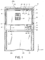
- the card slot assembly 200 has a card receiving portion 201 on the rear end thereof, as shown in Figs. 1 to 7 and 9.
- the card receiving portion 201 has a rectangular cross section in a plane perpendicular to a Y-direction, i.e. an XZ plane defined by an X-direction and a Z-direction.
- a card 300 such as an IC card, a memory card or a PC card can be inserted through the card receiving portion 201 along the Y-direction and can be received within the card slot assembly 200.
- the Y-direction is an insertion direction of the card 300. The inserted and received card 300 can be accessed by the electronic instrument.
- the card slot assembly 200 comprises a base insulator 10, which has a main plate 11 and two side walls 12.
- the main plate 11 has top and bottom surfaces 11a, 11b.
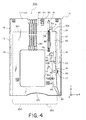
- the side walls 12 are positioned at the right and the left sides of the main plate 11 in the X-direction and extend in the Z-direction, as shown in Figs. 3 and 4.
- the base insulator 10 generally has a U-shaped cross-section in the XZ plane.
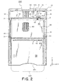
- a front cover 21 is fitted as shown in Figs. 1, 2, 7 and 8.
- a cover plate 22 and a slider 30 are disposed on or above the top surface 11a of the main plate 11.
- the cover plate 22 has a half size of the main plate 11 in the XY plane and covers the rear half of the main plate 11.
- the cover plate 22 and the base insulator 10 define the card receiving portion 201 at the rear end of the card slot assembly 200, as especially shown in Fig. 9.
- the slider 30 has a size of about one-third of the main plate 11 and is movable between the front cover 21 and the cover plate 22.
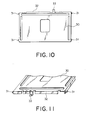
- the slider 30 is provided with four guided projections 31, as shown in Figs. 1, 2 and 10. Each two guided projections 31 are formed at the corresponding side of the slider 30. Each of the guided projections 31 is positioned at the lowest part of the slider 30 in the Z-direction, as shown in Fig. 11.
- the slider 30 is also provided with a front wall 32 and a control portion 33 which projects from the front wall 32, as shown in Fig. 11. As shown in Figs. 1 and 2, the front wall 32 is brought into contact with a front end 301 of the card 300 during the card insertion/ejection.
- the front end 301 presses the front wall 32, and the slider 30 is moved by the inserted card 300 to a position shown in Fig. 1, which position is referred to as a locked position.
- the slider 30 is moved to a position shown in Fig. 2, which position is referred to as an unlocked position.
- the slider 30 can move in the Y-direction between the locked position and the unlocked position.
- the main plate 11 is provided with an aperture 13, which is positioned at the middle of the main plate 11 in the X-direction and nearer to the rear end of the main plate 11 than to the front end thereof.
- an opening 14 is also formed in the main plate.
- the opening 14 is positioned between the aperture 13 and the right side wall 12.
- the opening 14 has a generally T-like shape, which has one edge extending in the Y-direction and the other edge extending therefrom in the X-direction.
- the main plate 11 is further formed with a first spring accommodation slit 15, which is positioned between the aperture 13 and the opening 14 in the X-direction and is positioned nearer to the front end of the main plate 11 than the opening 14 in the Y-direction.
- the first spring accommodation slit 15 extends in the Y-direction and has at the rear end thereof a hooked portion 15a.
- the main plate 11 is also formed with a second spring accommodation slit 16, which is positioned nearer to the rear end of the main plate 11 than the opening 14 in the Y-direction.
- the second spring accommodation slit 16 extends in the X-direction and has at the left end thereof a hooked portion 16a.
- a restriction slit 17 is formed in the main plate 11a.
- the restriction slit 17 is positioned between the opening 14 and the second spring accommodation slit 16 in the Y-direction and is positioned nearer to the right side wall 12 than the second spring accommodation slit 16 in the X-direction.
- the restriction slit 17 extends in the Y-direction.
- each of the side walls 12 is provided with two slider guide grooves 18, each of which accommodates the corresponding guided projection 31 of the slider 30.
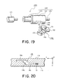
- the guided projection 31 is able to move within the corresponding slider guide groove 18 in accordance with the movement of the slider 30 in the Y-direction, as seen from Fig. 20.
- each of the slider guide grooves 18 has first to third portions 18a, 18b, 18c.
- the first and the third portions 18a and 18c extend in planes perpendicular to the Z-direction.
- the first portion 18a is positioned near to the front end of the side wall 12, while the third portion is positioned near to the rear end of the side wall 12.
- the first portion 18a is nearer to the bottom surface 11b of the main plate 11 than the third portion 18c.
- the second portion 18b extends in a direction oblique to the Y- and the Z-directions and connects the first and the third portions 18a, 18c.
- an ejection plate 50 is provided on the top surface 11a of the main plate 11 of the base insulator 10.
- the ejection plate 50 is elongated in the Y-direction and has front and rear ends 50a, 50b.
- a standing-wall portion 51 and a hooked portion 52 are formed at the front end 50a of the ejection plate 50, while a locked portion 53 is formed at the rear end 50b of the ejection plate 50.
- the standing-wall portion 51 extends upwards while the hooked portion 52 and the locked portion 53 extend downwards.
- the hooked portion 52 is positioned within the first spring accommodation slit 15 so that it is able to move within the first spring accommodation slit 15 in the Y-direction.
- the locked portion 53 is positioned within the opening 14 so that it is able to move within the opening 14 in the Y-direction.
- the standing-wall portion 51 is in contact with the front wall 32 of the slider 30. Therefore, when the ejection plate 50 goes rearwards, the slider 30 also goes rearwards. Conversely, when the slider 30 goes forwards, the ejection plate 50 also goes forwards.
- the standing-wall portion 51 is provided with a portion 51a, which serves to prevent the ejection plate from moving forwards to an unexpected position, i.e., a position nearer to the front end of the card slot assembly 200 than the locked position.
- a coil spring 60 is accommodated, as shown in Figs. 3 and 4.
- One end of the coil spring 60 is coupled to the hooked portion 15a of the first spring accommodation slit 15, while the other end of the coil spring 60 is coupled to the hooked portion 52 of the ejection plate 50.
- the coupling between the coil spring 60 and the ejection plate 50 is established within the first spring accommodation slit 15.
- the coil spring 60 pulls the hooked portion 52 rearwards and urges the ejection plate 50 to be positioned at the unlocked position.
- a pivot 70 is provided on the top surface 11a of the main plate 11 of the base insulator 10.
- the pivot 70 is formed integral with the main plate 11. The position of the pivot 70 is between the openings 14 and the second spring accommodation slit 16 and near to the restriction slit 17.
- a locking member 80 is provided, as shown in Figs. 3 and 4.
- the locking member 80 is provided with a center hole 81, as shown in Fig. 13.
- the locking member 80 has a protrusion 82 at a position near to the center hole 82, as shown in Fig. 13.
- the protrusion 82 is accommodated within the restriction slit 17 and is movable within the restriction slit 17.
- the protrusion 82 and the restriction slit 17 serve to restrict a rotation range of the locking member 80 to a predetermined rotation range, which includes a first rotational position shown in Fig. 3 and a second rotational position shown in Fig. 4.
- the locking member 80 has first and second ends. The first end is near to the front end of the card slot assembly 200, while the second end is near to the rear end of the card slot assembly 200.
- the center hole 81 mentioned above is positioned between the first and the second ends of the locking member 80.
- a locking portion 83 is formed, as shown in Figs. 13 and 14.
- the locking portion 83 has an L-like shape, one edge of which is always positioned between the ejection plate 50 and the top surface 11a of the main plate 11 of the base insulator 10, as shown in Figs. 3 and 4.
- a comer portion of the L-shaped locking portion 83 is brought into contact with the locked portion 53 of the ejection plate 50 and supports the rear side of the locked portion 53 so as to lock the ejection plate 50 at the locked position, opposing the coil spring 60.
- the moving direction of the ejection plate 50 is a direction opposite to the insertion direction and is referred to as an ejecting direction because the card 300 is ejected from the card slot assembly 200 upon the movement of the ejection plate 50 in this direction.
- a pressed portion 84 is also formed, as shown in Figs. 13 and 14.
- the pressed portion 84 projects in the same direction of the protrusion 82, as shown in Fig. 14.
- the pressed portion 84 is accommodated in the opening 14 and is able to move within the opening 14, as shown in Figs. 3 and 4.
- the pressed portion 84 projects over the bottom surface 11b of the main plate 11 of the base insulator 10, as shown in Fig. 7.
- a stopper portion 85 is formed, as shown in Figs. 13 and 14.
- the stopper portion 85 projects in a direction opposite to the direction of the pressed portion 84.
- the stopper portion 85 gets the back of the card 300.
- the stopper portion 85 can prevent the card 300 from going out of the card slot assembly 200 when the locking member 80 is positioned at the first rotational position.
- the stopper portion 85 moves to a position near the right side wall 12 of the base insulator 10 and does not obstruct the movement of the card 300 in the Y-direction, as shown in Fig. 4.
- a hooked hole 86 is formed, as shown in Figs. 3, 4, 13, and 14.
- a spring 90 is accommodated within the second spring accommodation slit 16, and the other end of the spring 90 is coupled to the hooked portion 16a.
- the spring 90 pulls the rear half of the locking member 80 towards the left side of the insulator 10 in Figs. 3 and 4 and compels the locking member 80 to be positioned at the first rotational position.
- a switch 100 is provided on the main plate 11 of the base insulator 10.
- the position of the switch 100 is near to the front end of the card slot assembly 200 in the Y-direction, as shown in Figs. 3 and 4, and corresponds to the position of the control portion 33 of the slider 30 in the X-direction, as shown in Figs. 1 and 2.
- the switch 100 has a controlled portion 101, as shown in Figs. 3 and 4.
- the controlled portion 101 is controlled by the control portion 33 of the slider 30 so that the switch 100 turns on.
- the control portion 33 is away from the controlled portion 101 so that the switch 100 turns off.
- a solenoid mechanism 110 is provided, as shown in Figs. 5 to 9.
- the solenoid mechanism 110 has power supply lines 111, as shown in Figs. 5 to 8.
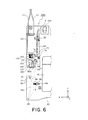
- the solenoid mechanism 110 movably supports a rod member 120 in an axial direction of the rod member 120, as shown in Figs, 5 and 6.
- the axial direction of the rod member 120 is the Y-direction.
- the rod member 120 is comprised of two parts 121, 122, as shown in Fig. 19.
- the part 121 is inserted into the solenoid mechanism 110 and is movably supported by the solenoid mechanism 110, as mentioned above.
- the other part 122 is fitted to the tip of the part 121 and is comprised of a fitted portion 123, a large-diameter portion 124 and a guided portion 125, which continue to each other in this order.
- the large-diameter portion 124 is formed with a groove 126, which extends in a direction perpendicular to the axial direction of the rod member 120.
- the guided portion 125 is slidably inserted into a guide hole 130a formed in a guiding wall 130 so that the movement of the rod member 120 in the Y-direction is guided by the guiding wall 130.
- the guiding wall 130 and the main part of the solenoid mechanism 110 provide a movable range of the rod member 120 between a first rod position and a second rod position.
- the first rod position is a position where the large-diameter portion 124 is in contact with the guiding wall 130.
- the second rod position is a position where the large-diameter portion 124 is farthest away from the guiding wall 130.
- a coil spring 140 is provided on the part 121 and the fitted portion 123 and between the main part of the solenoid mechanism 110 and the large-diameter portion 124.
- the coil spring 140 incites the rod member 120 to be positioned at the first rod position.
- the solenoid mechanism 110 turns on by receiving electric currents through the power supply lines 111, the rod member 120 is moved forward in the Y-direction to be positioned at the second rod position, opposing the coil spring 140.
- crank member 150 On the bottom surface 11b of the main plate 11 of the base insulator 10, a crank member 150 is also provided, as shown in Figs. 5 to 9.
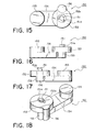
- the crank member 150 is comprised of three parts: a shaft 151, a main part 152 and a base part 153, as shown in Figs. 15 to 18.
- the base part 153 has a short cylinder and is fixed on the bottom surface 11b of the main plate 11 of the base insulator 10.
- the shaft 151 extends from the center of the base part 153 and has at its free end a key 151a which extends in a direction perpendicular to an axial direction of the shaft 151.
- the main part 152 has a disc-like shaped portion which has a center hole and a key groove 152a connected thereto.
- the main part 152 is rotated so that the main part 152 is positioned between the base part 153 and the key 151a and is prevented from being off the shaft 151. In this state, the main part 152 is rotatably supported by the shaft 151, which serves as a center axis of the main part 152.
- an arm portion 154 is connected on the lower surface of the main part 152 in Figs. 16 and 17, an arm portion 154 is connected.
- the arm portion 154 extends in a direction perpendicular to the center axis of the main part 152.
- a cylindrical projection 155 is formed at the free end of the arm portion 154.
- the projection 155 projects in a direction parallel to the shaft 151.
- the projection 155 is fitted within the groove 126 of the rod member 120, as shown in Fig. 19.
- the projection 155 is sized to be suitably received within the groove 126 of the rod member 120, as shown in Figs. 5 and 6. Therefore, when the rod member 120 moves in the axial direction thereof, the projection 155 can rotate and slide within the groove 126 of the rod member 120, while pivoting upon the shaft 151, as seen fro the Figs. 5 and 6.
- the main part 152 is also formed with a pressing portion 156, as shown in Figs. 5, 6, 15, 17 and 18.
- the pressing portion 156 extends in the same direction as the projecting direction of the projection 155, as shown in Fig. 15 and 18.
- the pressing portion 156 is arranged away from the shaft 151.
- a line passing through the pressing portion 156 and the shaft 151 and the arm portion 154 make a right angle, as shown in Fig. 15.
- the pressing portion 156 also pivots upon the shaft 151 so that the straight movement of the rod member 120 is converted, by the crank member 150, into the pivoting or rotating movement of the pressing portion 156.
- the rotational movement of the pressing portion 156 provides a rotation force on the pressed portion 84 of the locking member 80.
- the pressing portion 156 is positioned on the side of the pressed portion 84 of the locking member 80, as shown in Fig. 5.
- the pressing portion 156 is in contact with the side of the pressed portion 84.
- Fig. 21 shows the ejection mechanism as seen from the bottom thereof.
- the locking member 80 turns counterclockwise in accordance with the force of the spring 90.
- the L-like shaped locking portion 83 of the locking member 80 receives the locked portion 53 of the ejection plate 50 so as to lock the ejection plate 50 at the locked position.
- the rod member 120 is moved to the first rod position.
- the crank member 150 converts the straight movement of the rod member 120 into the rotation force and transmits the rotation force to the pressed portion 84 of the locking member 80.
- the locking portion 83 is moved away from the locked portion 53 so that the locking member 80 unlocks the ejection plate 50.
- the ejection plate 50 is allowed to be moved to the ejecting position in accordance with the force of the coil spring 60.
- the card slot assembly 200 can be used in the following manner for the reliable data transmission between the electronic instrument provided with the card slot assembly 200 and the card 300 inserted into the card slot assembly 200. It is detected whether the card is accessed by the electronic instrument. Such a detection can by achieved by monitoring the data transmission, and the monitoring can be easily achieved in the form of a hardware or a software. The detection may use another detection of the condition of the switch 100.
- the solenoid mechanism 110 is allowed to move the rod member 120 to the second rod position only when the electronic instrument does not access the card.
- the solenoid mechanism 110 is turned on only when the electronic instrument does not access the card. During the data transmission, the solenoid mechanism 100 is turned off and is forced to keep the rod member 120 at the first rod position. In the above-mentioned application, the highly reliable data transmission is achieved because there is no misoperation of an eject button.
Landscapes
- Physics & Mathematics (AREA)
- General Physics & Mathematics (AREA)
- Engineering & Computer Science (AREA)
- Theoretical Computer Science (AREA)
- Coupling Device And Connection With Printed Circuit (AREA)
- Details Of Connecting Devices For Male And Female Coupling (AREA)
Abstract
Description
Claims (13)
- A card slot assembly (200) which has a card receiving portion (201) for receiving a card (300) in an insertion direction within the card slot assembly (200), the card slot assembly (200) comprising:ejecting means (50), which is movable along the insertion direction between a locked position and an ejecting position, wherein the ejecting means (50) moves to the locked position when the card (300) is received within the card slot assembly (200), while the ejecting means (50) exerts on the received card (300) an ejection force in an ejection direction opposite to the insertion direction when the ejecting means (50) moves from the locked position to the ejecting position;urging means (60), which is coupled to the ejecting means (50) and urges the ejecting means (50) to be positioned at the ejecting position;a pivot (70);a locking member (80), which is rotatably supported by the pivot (70), wherein a rotational range of the locking member (80) is between a first rotational position and a second rotational position, the locking member (80) locks the ejecting means (50) at the locked position when the locking member (80) is positioned at the first rotational position, and the locking member (80) unlocks the ejecting means (50) when the locking member (80) is positioned at the second rotational position, so as to allow the ejecting means (50) to move in the ejecting direction in accordance with the urging means (60);a solenoid mechanism (110) supporting a rod member (120) movably in an axial direction of the rod member (120) between a first rod position and a second rod position; andcrank means (150), which is coupled to the rod member (120) and is positioned close to the locking member (80), wherein, when the rod member (120) moves from the first rod position to the second rod position, the crank means (150) converts the movement of the rod member (120) into a rotation force and rotates the locking member (80) from the first rotational position towards the second rotational position by means of the rotation force.
- The card slot assembly (200) according to claim 1, wherein:the rod member (120) is provided with a groove (126), which is formed in the rod member (120) and extends in a direction perpendicular to the axial direction; the crank means (150) comprises a main portion (152) and an arm portion (154); the main portion (152) has a center axis (151); the arm portion (154) extends in an extending direction and is coupled to the main portion (152) so that one end of the arm portion (154) is able to pivot upon the center axis (151) of the main portion (152); and the arm portion (154) is provided with a projection (155), which projects in a projecting direction perpendicular to the extending direction and is fitted within the groove (126) so that the projection (155) is able to rotate and to slide within the groove (126) and is able to pivot upon the center axis (151) of the main portion (152) when the rod member (120) moves between the first and the second rod positions.
- The card slot assembly (200) according to claim 2, wherein:the locking member (80) has a pressed portion (84); the crank means (150) further comprises a pressing portion (156), which is supported by the main portion (152) apart from the center axis (151) so that the pressing portion (156) pivots upon the center axis (151) of the main portion (152) when the projection (155) pivots upon the center axis (151); and the pressing portion (156) is in contact with the pressed portion (84) when the rod member (120) is positioned at the first rod position, while the pressing portion (156) presses the pressed portion (84) when the rod member (120) is moved towards the second rod position.
- The card slot assembly (200) according to claim 3, wherein the pressed portion (84) and the pressing portion (156) extend in the same direction as the projecting direction of the projection (155) so that, when the pressing portion (156) pivots upon the center axis (151), the pressing portion (156) presses the pressed portion (84) in a direction perpendicular to the projecting direction.
- The card slot assembly (200) according to one of claims 1 to 4, further comprising compelling means (90) for compelling the locking member (80) to be positioned at the first rotational position so that, when the rod member (120) moves from the first rod position to the second rod position, the crank means (150) supplies the rotation force on the locking member (80), opposing the compelling means (90).
- The card slot assembly (200) according to one of claims 1 to 5, wherein: the solenoid mechanism (110) is provided with inciting means (140) for inciting the rod member (120) to be positioned at the first rod position; and, when the solenoid mechanism (110) is turned on, the rod member (120) moves to the second rod position, opposing the inciting means (140).
- The card slot assembly (200) according to one of claims 1 to 6, further comprising a base insulator (10), on which the ejecting means (50), the pivot (70), the locking member (80), the solenoid mechanism (110) and the crank means (150) are mounted, wherein: the base insulator (10) is formed with a slit (17); the locking member (80) is provided with a protrusion (82) which is accommodated in the slit (17) and is movable within the slit (17); and the protrusion (82) and the slit (17) restrict the rotation range of the locking member (80) to a predetermined range which includes the first and the second rotational positions.
- The card slot assembly (200) according to claim 7, wherein:the base insulator (10) has top and bottom surfaces (11a, 11b) and an opening (14) between the top and the bottom surfaces (11a, 11b); the ejecting means (50), the pivot (70) and the locking member (80) are provided on the top surface (11a), while the solenoid mechanism (110) andthe crank means (150) are provided on the bottom surface (11b); and the locking member (80) and the crank means (150) are accessible to each other through the opening (14).
- The card slot assembly (200) according to one of claims 1 to 8, wherein the axial direction of the rod member (120) is the same direction as the insertion direction.
- The card slot assembly (200) according to one of claims 1 to 9, wherein: the ejecting means (50) comprises an ejection plate (50) elongated in the insertion direction; the ejection plate (50) has a first end (50a) and a second end (50b) which is nearer to the card receiving portion (201) than the first end (50a); and the ejection plate (50) is provided with a standing-wall portion (51) which is formed at the first end (50a) and is laid on a plane perpendicular to the insertion direction so that, when the card (300) is inserted into the card slot assembly (200), the standing-wall portion (51) receives a force caused by the insertion of the card (300) and moves the ejection plate (50) to the locked position, while, when the ejection plate (50) moves from the locked position to the ejecting position, the standing-wall portion (51) exerts the ejection force on the card (300).
- The card slot assembly (200) according to one of claims 1 to 10, wherein: the locking member (80) is provided with a stopper portion (85), which is positioned away from the pivot (70) and near to the card receiving portion (201) and turns in accordance with the movement of the locking member (80) so that, when the card (300) is received within the card slot assembly (200) and the locking member (80) is positioned at the first rotational position, the stopper portion (85) is positioned nearer to the card receiving portion (201) than the received card (300) to prevent the card (300) from going out of the card slot assembly (200).
- The card slot assembly (200) according to one of claims 1 to 11, further comprising a switch (100) and a slider (30) slidable along the insertion direction in accordance with the movement of the card (300) being received within the card slot assembly (200), wherein the slider (30) is provided with a control portion (33) which turns on the switch (100) when the card (300) is completely received within the card slot assembly (200) and which turns off the switch (100) when the card (300) is ejected from the card slot assembly (200).
- A method of using the card slot assembly (200) according to one of claims 1 to 12, comprising steps of:installing the card slot assembly (200) in an electronic instrument which is able to access the card (300) received within the card slot assembly (200);detecting whether the card (300) is accessed by the electronic instrument; andin a case where the card (300) is accessed by the electronic instrument, forcing the solenoid mechanism (110) to keep the rod member (120) at the first rod position.
Applications Claiming Priority (2)
| Application Number | Priority Date | Filing Date | Title |
|---|---|---|---|
| JP2002203215A JP2004047275A (en) | 2002-07-11 | 2002-07-11 | Connector with card eject mechanism |
| JP2002203215 | 2002-07-11 |
Publications (2)
| Publication Number | Publication Date |
|---|---|
| EP1394730A1 true EP1394730A1 (en) | 2004-03-03 |
| EP1394730B1 EP1394730B1 (en) | 2005-06-01 |
Family
ID=30112669
Family Applications (1)
| Application Number | Title | Priority Date | Filing Date |
|---|---|---|---|
| EP03015892A Expired - Lifetime EP1394730B1 (en) | 2002-07-11 | 2003-07-11 | Card slot assembly with electrically-controllable ejection mechanism |
Country Status (5)
| Country | Link |
|---|---|
| US (1) | US6878003B2 (en) |
| EP (1) | EP1394730B1 (en) |
| JP (1) | JP2004047275A (en) |
| CN (1) | CN1231866C (en) |
| DE (1) | DE60300761T2 (en) |
Families Citing this family (14)
| Publication number | Priority date | Publication date | Assignee | Title |
|---|---|---|---|---|
| JP4007974B2 (en) * | 2004-06-09 | 2007-11-14 | 日本航空電子工業株式会社 | Card connector |
| JP4030119B2 (en) * | 2004-06-30 | 2008-01-09 | 日本航空電子工業株式会社 | Card connector |
| DE102004040448B4 (en) * | 2004-08-20 | 2010-01-21 | Amphenol-Tuchel Electronics Gmbh | Pushmatic Smart Card Connector |
| JP4076180B2 (en) * | 2005-03-31 | 2008-04-16 | 日本航空電子工業株式会社 | Card connector |
| TWM299329U (en) * | 2006-04-28 | 2006-10-11 | Tai Sol Electronics Co Ltd | Card connector with card insertion detecting function |
| TWI382609B (en) * | 2010-05-11 | 2013-01-11 | Hon Hai Prec Ind Co Ltd | Electronic appartus and pop-up device of the same |
| CN102738618B (en) * | 2011-04-15 | 2015-02-04 | 索尼爱立信移动通讯有限公司 | Storage card base, mobile terminal and method for protecting storage card |
| CN102902989B (en) * | 2011-07-27 | 2016-01-06 | 索尼爱立信移动通讯有限公司 | The guard method of card reader, electronic equipment and storage card |
| US9787342B2 (en) * | 2014-09-05 | 2017-10-10 | Apple Inc. | Subscriber identity module (SIM) ejector |
| US9837765B2 (en) | 2015-06-25 | 2017-12-05 | Microsoft Technology Licensing, Llc | Apparatus for ejecting at least one integrated circuit card |
| US10970696B1 (en) * | 2019-10-04 | 2021-04-06 | Capital One Services, Llc | Techniques to provide physical transaction card capabilities for a mobile device |
| CN120361440A (en) * | 2019-10-29 | 2025-07-25 | 中硼(厦门)医疗器械有限公司 | Radiation therapy system and method of operating positioning device |
| CN114098998B (en) * | 2020-08-31 | 2023-08-01 | 疆域康健创新医疗科技成都有限公司 | Ejecting device |
| CN112105214A (en) * | 2020-09-09 | 2020-12-18 | 加弘科技咨询(上海)有限公司 | Quick connection structure and wire arranging frame applied by same |
Citations (2)
| Publication number | Priority date | Publication date | Assignee | Title |
|---|---|---|---|---|
| EP0363992A2 (en) * | 1988-10-14 | 1990-04-18 | Omron Corporation | Card reader having locking mechanism |
| EP1035495A2 (en) * | 1999-03-08 | 2000-09-13 | Matsushita Electric Industrial Co., Ltd. | IC card reader |
Family Cites Families (3)
| Publication number | Priority date | Publication date | Assignee | Title |
|---|---|---|---|---|
| US5077722A (en) * | 1989-01-06 | 1991-12-31 | Convex Computer Corporation | Disk drive insertion and removal interlock |
| JPH08161233A (en) | 1994-12-05 | 1996-06-21 | Hitachi Ltd | Memory card system |
| JP3200736B2 (en) | 1999-05-25 | 2001-08-20 | 日本航空電子工業株式会社 | Connector with card lock mechanism |
-
2002
- 2002-07-11 JP JP2002203215A patent/JP2004047275A/en active Pending
-
2003
- 2003-07-09 CN CNB031475078A patent/CN1231866C/en not_active Expired - Fee Related
- 2003-07-11 EP EP03015892A patent/EP1394730B1/en not_active Expired - Lifetime
- 2003-07-11 DE DE60300761T patent/DE60300761T2/en not_active Expired - Lifetime
- 2003-07-11 US US10/618,318 patent/US6878003B2/en not_active Expired - Lifetime
Patent Citations (2)
| Publication number | Priority date | Publication date | Assignee | Title |
|---|---|---|---|---|
| EP0363992A2 (en) * | 1988-10-14 | 1990-04-18 | Omron Corporation | Card reader having locking mechanism |
| EP1035495A2 (en) * | 1999-03-08 | 2000-09-13 | Matsushita Electric Industrial Co., Ltd. | IC card reader |
Also Published As
| Publication number | Publication date |
|---|---|
| CN1231866C (en) | 2005-12-14 |
| DE60300761T2 (en) | 2006-05-04 |
| US6878003B2 (en) | 2005-04-12 |
| CN1471048A (en) | 2004-01-28 |
| DE60300761D1 (en) | 2005-07-07 |
| US20040009690A1 (en) | 2004-01-15 |
| EP1394730B1 (en) | 2005-06-01 |
| JP2004047275A (en) | 2004-02-12 |
Similar Documents
| Publication | Publication Date | Title |
|---|---|---|
| EP1394730B1 (en) | Card slot assembly with electrically-controllable ejection mechanism | |
| US5836775A (en) | Connector apparatus | |
| JP3529394B2 (en) | IC card information processing device | |
| US6270365B1 (en) | IC card connector having IC card ejection mechanism | |
| FI121200B (en) | The card connector | |
| KR100304213B1 (en) | Disk device | |
| JPH0896089A (en) | IC card information processing device | |
| JPH09305257A (en) | Electronic processing system | |
| EP1324256B1 (en) | Card connector | |
| JP2002289299A (en) | Card connector device | |
| EP1170692B1 (en) | A smart-card reader | |
| US6960091B2 (en) | Card connector | |
| JP3657016B2 (en) | Connector device | |
| JPH0823878B2 (en) | Card writing / reading device | |
| JP3388995B2 (en) | Expansion device and electronic processing system having the same | |
| JPH07192805A (en) | Data processing medium connector and data processing medium locking mechanism | |
| JP2024145349A (en) | Electric lock | |
| JPH07271925A (en) | Portable electronic devices | |
| JP2742339B2 (en) | Storage media drive device | |
| US7873968B2 (en) | Position detecting device of an optical drive | |
| JP2002289300A (en) | Card connector device | |
| JP2002033031A (en) | Power tool switch mechanism | |
| JP2551456Y2 (en) | Multi-pole connector | |
| JP3248507B2 (en) | Card processing equipment | |
| JP2011171142A (en) | Card connector |
Legal Events
| Date | Code | Title | Description |
|---|---|---|---|
| PUAI | Public reference made under article 153(3) epc to a published international application that has entered the european phase |
Free format text: ORIGINAL CODE: 0009012 |
|
| AK | Designated contracting states |
Kind code of ref document: A1 Designated state(s): AT BE BG CH CY CZ DE DK EE ES FI FR GB GR HU IE IT LI LU MC NL PT RO SE SI SK TR |
|
| AX | Request for extension of the european patent |
Extension state: AL LT LV MK |
|
| 17P | Request for examination filed |
Effective date: 20040604 |
|
| GRAP | Despatch of communication of intention to grant a patent |
Free format text: ORIGINAL CODE: EPIDOSNIGR1 |
|
| AKX | Designation fees paid |
Designated state(s): DE FR GB |
|
| GRAS | Grant fee paid |
Free format text: ORIGINAL CODE: EPIDOSNIGR3 |
|
| GRAA | (expected) grant |
Free format text: ORIGINAL CODE: 0009210 |
|
| AK | Designated contracting states |
Kind code of ref document: B1 Designated state(s): DE FR GB |
|
| REG | Reference to a national code |
Ref country code: GB Ref legal event code: FG4D |
|
| REF | Corresponds to: |
Ref document number: 60300761 Country of ref document: DE Date of ref document: 20050707 Kind code of ref document: P |
|
| ET | Fr: translation filed | ||
| PLBE | No opposition filed within time limit |
Free format text: ORIGINAL CODE: 0009261 |
|
| STAA | Information on the status of an ep patent application or granted ep patent |
Free format text: STATUS: NO OPPOSITION FILED WITHIN TIME LIMIT |
|
| 26N | No opposition filed |
Effective date: 20060302 |
|
| REG | Reference to a national code |
Ref country code: FR Ref legal event code: PLFP Year of fee payment: 14 |
|
| REG | Reference to a national code |
Ref country code: FR Ref legal event code: PLFP Year of fee payment: 15 |
|
| REG | Reference to a national code |
Ref country code: FR Ref legal event code: PLFP Year of fee payment: 16 |
|
| PGFP | Annual fee paid to national office [announced via postgrant information from national office to epo] |
Ref country code: FR Payment date: 20210611 Year of fee payment: 19 |
|
| PGFP | Annual fee paid to national office [announced via postgrant information from national office to epo] |
Ref country code: GB Payment date: 20210616 Year of fee payment: 19 |
|
| PGFP | Annual fee paid to national office [announced via postgrant information from national office to epo] |
Ref country code: DE Payment date: 20210616 Year of fee payment: 19 |
|
| REG | Reference to a national code |
Ref country code: DE Ref legal event code: R119 Ref document number: 60300761 Country of ref document: DE |
|
| GBPC | Gb: european patent ceased through non-payment of renewal fee |
Effective date: 20220711 |
|
| PG25 | Lapsed in a contracting state [announced via postgrant information from national office to epo] |
Ref country code: FR Free format text: LAPSE BECAUSE OF NON-PAYMENT OF DUE FEES Effective date: 20220731 |
|
| PG25 | Lapsed in a contracting state [announced via postgrant information from national office to epo] |
Ref country code: GB Free format text: LAPSE BECAUSE OF NON-PAYMENT OF DUE FEES Effective date: 20220711 Ref country code: DE Free format text: LAPSE BECAUSE OF NON-PAYMENT OF DUE FEES Effective date: 20230201 |