EP1394707A1 - Medical information system - Google Patents
Medical information system Download PDFInfo
- Publication number
- EP1394707A1 EP1394707A1 EP02711398A EP02711398A EP1394707A1 EP 1394707 A1 EP1394707 A1 EP 1394707A1 EP 02711398 A EP02711398 A EP 02711398A EP 02711398 A EP02711398 A EP 02711398A EP 1394707 A1 EP1394707 A1 EP 1394707A1
- Authority
- EP
- European Patent Office
- Prior art keywords
- patient
- server
- network
- care provider
- medical care
- Prior art date
- Legal status (The legal status is an assumption and is not a legal conclusion. Google has not performed a legal analysis and makes no representation as to the accuracy of the status listed.)
- Ceased
Links
Images






Classifications
-
- G—PHYSICS
- G06—COMPUTING OR CALCULATING; COUNTING
- G06Q—INFORMATION AND COMMUNICATION TECHNOLOGY [ICT] SPECIALLY ADAPTED FOR ADMINISTRATIVE, COMMERCIAL, FINANCIAL, MANAGERIAL OR SUPERVISORY PURPOSES; SYSTEMS OR METHODS SPECIALLY ADAPTED FOR ADMINISTRATIVE, COMMERCIAL, FINANCIAL, MANAGERIAL OR SUPERVISORY PURPOSES, NOT OTHERWISE PROVIDED FOR
- G06Q10/00—Administration; Management
- G06Q10/10—Office automation; Time management
-
- G—PHYSICS
- G16—INFORMATION AND COMMUNICATION TECHNOLOGY [ICT] SPECIALLY ADAPTED FOR SPECIFIC APPLICATION FIELDS
- G16H—HEALTHCARE INFORMATICS, i.e. INFORMATION AND COMMUNICATION TECHNOLOGY [ICT] SPECIALLY ADAPTED FOR THE HANDLING OR PROCESSING OF MEDICAL OR HEALTHCARE DATA
- G16H10/00—ICT specially adapted for the handling or processing of patient-related medical or healthcare data
- G16H10/40—ICT specially adapted for the handling or processing of patient-related medical or healthcare data for data related to laboratory analysis, e.g. patient specimen analysis
-
- G—PHYSICS
- G16—INFORMATION AND COMMUNICATION TECHNOLOGY [ICT] SPECIALLY ADAPTED FOR SPECIFIC APPLICATION FIELDS
- G16H—HEALTHCARE INFORMATICS, i.e. INFORMATION AND COMMUNICATION TECHNOLOGY [ICT] SPECIALLY ADAPTED FOR THE HANDLING OR PROCESSING OF MEDICAL OR HEALTHCARE DATA
- G16H10/00—ICT specially adapted for the handling or processing of patient-related medical or healthcare data
- G16H10/60—ICT specially adapted for the handling or processing of patient-related medical or healthcare data for patient-specific data, e.g. for electronic patient records
Definitions
- the present invention relates to a medical information system adapted to a home health care.
- a system disclosed in Japanese laid-open patent publication No. 8-38435 has a plurality of patient terminals for transmitting measured vital data, a single of server for storing and managing the vital data received from these patient terminals, and a plurality of doctor terminals for obtaining or browsing the vital information retained in the single of server.
- load to the server at data correction processes is increased with increasing of the number of the patient terminals.
- the loads to the server at data browsing processes are also increased with the increasing of the number of the patient terminals.
- These increases of the loads to the server cause a delay in response time and decreasing in a transmission rate.
- extremely heavy loads to the server may result in that the data collection from the patient terminals and the data browsing from the doctor terminals would be impossible.
- the single server can not satisfy both requirements from a system administrator and requirements inconsistent with the system administrator's requirement from medical institutions such as hospitals that are users of the doctor terminals.
- the system administrator generally demands to hold the server so as to operate and manage it.
- the medical institutes demand to hold the server so as to make it able to use the vital data collected from the patient terminals in other medical information systems such as an electronic chart system.
- the single server has a low level of security property: Specifically, third parties with bad faith may access to the vital information by using the patient terminal without proper authentication.
- objects of the present invention are to reduce the loads to the server, enhance flexibility of the system, and improve security properties.
- a first aspect of the present invention provides a medical information system comprising: a patient server that can receive vital information, firstly retain the received vital information, and transmit the retained vital information; and a medical care provider server connected to the patient server through a first network, the medical care provider server being capable of retaining the vital information received from the patient server through the first network and allowing the retained vital information to be browsed or viewed.
- the medical information system further comprises a patient terminal connected to the patient server through a second network, the patient terminal being capable of transmitting the vital information to the patient server through the second network; and a doctor terminal connected to the medical care provider server through a third network, the doctor terminal being capable of browsing the vital information retained in the medical care provider server through the third network.
- the patient server processes collection of the vital information from the patient terminal
- medical care provider server processes browsing of the vital information by the doctor terminal.
- the processes are decentralized by concurrent processes in the servers, thereby reducing loads to each of the respect servers.
- response time is shortened, resulting in improvement of communication speed.
- stability of the system is improved by reducing the loads to the patient server and the medical care provider server. This enables the collection of the vital information form the patient terminal and the browsing of the vital information by the doctor terminal to be always executed in a stable manner.
- the patient terminal is connected to the patient server, whereas the doctor terminal is connected to the medical care provider server. Accordingly, when a server program is modified so as to adapt the program to changes in specification or addition of the patient terminal, only the patient server needs to be downed, whereas the browsing of the vital information retained in the medical care provider server by the doctor terminal can be continued. Controversy, when the server program is modified so as to adapt the program to changes in specification or addition of the doctor terminal, only the medical care provider server needs to be downed, whereas the collection of the vital information by the patient server can be continued.
- the system administrator can hold the patient server to operate and manage it, thereby the maintenance and operation of the data being simplified.
- the medical institute can hold the medical care provider server so as to use the vital information retained in the medical care provider server for other medical information systems such as the electronic chart system.
- the medical information system according to the first aspect of the present invention has high flexibility.
- the patient terminal is provided with a sensor for measuring vital data, and the vital information includes a measured value by the sensor.
- the medical care provider server can transmit the inquiry received from the doctor terminal to the patient server through the first network.
- the patient server may transmit the inquiry received from the medical care provider server to the patient terminal through the second network.
- the vital information transmitted from the patient terminal to the patient server through the second network may include a reply to the inquiry transmitted to the patient terminal.
- the medical information system includes a first unauthorized access prevention section provided in the first network, a second unauthorized access prevention section provided in the second network and a third unauthorized access prevention section provided in the third network.
- the first and third unauthorized access prevention sections preferably have higher security levels than that of the second unauthorized access prevention section.
- the first unauthorized access prevention section is provided with a firewall and a virtual private network
- the second unauthorized access prevention section is provided with a remote access server
- the third unauthorized access prevention section is provided with a terminal authentication server.
- the patient server only can be accessed directly from the patient terminal through the second network.
- the first unauthorized access prevention section provided in the first network for communicating the patient server and the medical care provider server has higher security level than that of the second unauthorized access prevention section. Accordingly, unauthorized access from the patient server to the vital information retained in the medical care provider server can be prevented.
- the lower security level of the second unauthorized access prevention section than those of the first and third unauthorized access prevention sections ensures a convenient connection from the patient terminal to the patient server.
- the high security level of the third network for connecting the doctor terminal and the care provider server prevents unauthorized access in direct to the medical care server. In these meanings, the medical information system according to the first aspect of the present invention has very high level of security.
- the patient server and the medical care provider server may be respectively clustered. Clustering of the patient server and the medical care provider server makes it possible to realize further decentralization of the loads to them. The clustering also improves fault tolerance and makes it possible to realize a system that does not stop 24 hours a day.
- a second aspect of the invention provides a medical information system comprising: a plurality of patient servers that can receive vital information, firstly retain the received vital information, and transmit the retained vital information; a medical care provider server connected to the patient servers through a first network, the medical care provider server being capable of retaining the vital information received from the patient servers through the first network and allowing the retained vital information to be browsed; a plurality of patient terminals respectively connected to the patient server through a second network, the patient terminals being capable of transmitting the vital information to the patient server through the second network; and a doctor terminal connected to the medical care provider server through a third network, the doctor terminal being capable of browsing the vital information retained in the medical care provider server through the third network.
- the medical information system when a server program is modified so as to adapt the program to change in specification or addition of the patient terminals connected to one of the plurality of patient servers, only corresponding patient server needs to be downed.
- the other patient servers can continue to collect the vital information form the patient terminals connected thereto.
- a third aspect of the present invention provides a medical information system comprising: a patient server that can receive vital information, firstly retain the received vital information, and transmit the retained vital information; a plurality of medical care provider servers respectively connected to the patient server through a first network, the medical care provider servers being capable of retaining the vital information received from the patient server through the first network and allowing the retained vital information to be browsed; a patient terminal connected to the patient server through a second network, the patient terminal being capable of transmitting the vital information to the patient . server through the second network; and a plurality of doctor terminals respectively connected to the medical care provider server through a third network, the doctor terminals being capable of browsing the vital information retained in the medical care provider servers through the third network.
- the plurality of medical care provider servers can be respectively held and managed by corresponding medical institutes. Accordingly, each of the medical institutes can retain the vital information in its medical care provider server for long term. Further, views at doctor terminals when the vital information is browsed can be customized in accordance with each of the medical institutes.
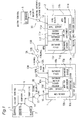
- Fig. 1 is a block diagram showing a medial information system according to a first embodiment of the present invention
- Fig. 2 is a schematic block diagram showing the medical information system according to the first embodiment of the present invention.
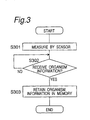
- Fig. 3 is a flow chart for explaining measurement of vital information
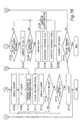
- Figs 4A and 4B are respectively a flow chart for explaining transmission of the vital information from a patient terminal to a patient server;
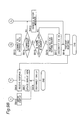
- Figs. 5A and 5B are respectively a flow chart for explaining transmission of the vital information from the patient server to a medical care provider server;
- Figs. 6A and 6B are respectively a flow chart for explaining browsing of the vital data retained in the medical care provider server by a doctor terminal;
- Figs. 7A and 7B are respectively a flow chart for explaining transmission of a medical inquiry from the doctor terminal to the medical care provider server;
- Figs. 8A and 8B are respectively a flow chart for explaining transmission of the medical inquiry from the care provider to the patient server;
- Figs. 9A and 9B are respectively a flow chart for explaining transmission of a reply to the medical inquiry from the patient server to the patient terminal;
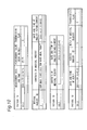
- Fig. 10 is a schematic view showing an example of a data structure of the patient server
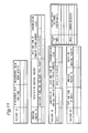
- Fig. 11 is a schematic view showing an example of a data structure of the medical care provider server
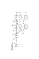
- Fig. 12 is a schematic block diagram showing a medical information system according to a second embodiment of the present invention.
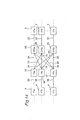
- Fig. 13 is a schematic block diagram showing a medical information system according to a third embodiment of the present invention.
- Fig. 14 is a schematic block diagram showing a medical information system according to a fourth embodiment of the present invention.
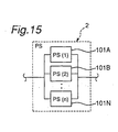
- Fig. 15 is a schematic block diagram showing an example of a clustered patient server.
- a medical information system As illustrated in Figs. 1 and 2, a medical information system according to a first embodiment of the present invention is provided with a patient server (PS) 1 and a medical care provider server (CPS) 2 connected with each other through a first network 3A. Further, this medical information system is provided with a plurality of patient terminals (PT) 4 respectively connected to the patient server 1 through a second network 3B, and a plurality of doctor terminals (DT) 5 connected to the medical care provider server 2 through a third net work 3C.
- PS patient server
- CPS medical care provider server
- DT doctor terminals
- vital data is transmitted from the patient terminal 4 to the patient server 1 through the second network 4.
- the vital data includes a measurement value and a reply to a medical inquiry (inquiry).
- the patient server 1 temporally retains the vital data received from the patient terminals 4.
- the patient server 1 transmits the vital data retained therein to the medical care provider server 2 through the first network 3A in accordance with a request from the medical care provider server 2.
- the medical care provider server 2 retains the vital information received from the patient serer 1.
- the data stored in the medical care provider server 2 can be browsed or viewed from the doctor terminal through the third network 3C.
- the patient terminal 4 for instance, consists of a personal computer to which a plurality of sensors 7 for measuring the vital data of patients are connected.
- sensors 7 for example, includes a hemadynamometer and a scale.
- the patient server 1 is provided with Web server software 10b which runs on an operating system 10a.
- Windows 2000® from Microsoft may be adopted as the operating system 10a.
- Internet Information Server® IIS
- IIS Internet Information Server
- an application execution environment 10c application server software 10d
- server program 10e operated on an application execution environment 10c
- JVM Java Virtual Machine®
- JRUN® from Macromedia
- JDBC® from Inet can be adopted as the database driver 10f.
- the database driver 10f manipulates database files 10h using a database server 10g as an interface.
- the care provider server 2 is provided with web server software 11b (e.g. IIS from Microsoft) operated on an operating system 11a (e.g. Windows 2000® from Microsoft). Further, operated on an application execution environment 11c (e.g. JVM from Jabasoft) are application server software 11d (e.g. JRUN from Macromedia), a server program 11e, and a database driver 11f (e.g. JDBC from Inet). The database driver 11f manipulates database files 11h using a database server 11g as an interface. Furthermore, the medical care provider server 2 is provided with HTML and a scrip 11i manipulated on the Web server software 11b.
- web server software 11b e.g. IIS from Microsoft
- an operating system 11a e.g. Windows 2000® from Microsoft
- an application execution environment 11c e.g. JVM from Jabasoft
- application server software 11d e.g. JRUN from Macromedia
- server program 11e e.g. JRUN from Macromedia
- the doctor terminal 5 consists of, for example, a normal personal computer. As described later, the doctor terminal 5 is provided with browser software for communicating with the medical care provider server 2.
- the first network for connecting the patient server 1 and the medical care provider server 2 is provided with a firewall 12A and a virtual private network (VPN) 13A for the patient server 1 as well as a firewall 12B and a VPN 13B for the medical care provider server 2.
- VPN virtual private network
- the second network for communicating each of the patient terminals 4 and the patient server 1 is provided with a remote access server (RAS) 15 connected to each of the patient terminals 4 through a phone line 14 and a local area network 16.
- RAS remote access server
- the third network 3C for communicating each of the doctor terminals 5 and the medical care provider server 2 is provided with a terminal authentication server 18.
- the sensor 7 for measuring performs measurement of the vital data such as blood pressure, body temperature, or body weight. Then, if the patient terminal 4 receives the vital data at step S302, then it retains the data in its memory at step S303.
- Figs. 4A and 4B illustrate processes until the vital data retained in the memory of the patient terminal 4 is transmitted to the patient server 1.
- the vital data retained in the memory of the patient terminal 4 includes the reply to the inquiry that have been transmitted to the patient server 4 from the doctor terminal 5 through the medical care provider server 2 and the patient server 1.
- the patient terminal 4 requires access to the RAS 15 by meahs of dial-up connection through the phone-line 14.
- the RAS 15 performs authentication of the patient terminal 4 being requiring the access by means of password at step S409, and then transmits a result of the authentication to the patient terminal 4 at step S410.
- the patient server 4 performs error display at step S403 and disconnects the dial-up connection at step S408.
- the patient terminal 4 checks whether or not there is a vital data not transmitted yet in the memory. If the any vital data not transmitted yet exits, then the patient terminal 4 transmits a request for data transmission to the patient server 4 at step S405. After receiving the request at step S411, in case that activation of the server program 10e succeeds at step S412, the patient server 1 performs connection to the database files 10h at step S413.
- the patient server 1 writes the data to the database files 10h at step s415 followed by disconnection of the database files 10h at step S416.
- an error message is generated at step S418.
- the patient server 1 transmits a response to the patient terminal 4 at step S417.
- the patient terminal 4 After receiving the response from the patient server 1 at step S406 and updating a screen view at step S407, the patient terminal 4 disconnects the dial-up connection at step S408.
- Figs. 5A and 5B illustrate processes until the vital data has been transmitted from the patient server to the medical care provider server 2.
- the firewall 12B for the medical care provider server 2 performs authentication at step S502. If the authentication by the firewall 12B has been approved at step S503, then the VPN 13B for the medical care provider server 2 performs further authentication at step S504. In case that the authentication by the VPN 13B has been approved at step S505, that connection to the medical care provider server 4 is possible at step S506, and that the patient server 1 can be connected to the database files 10h thereof at step S507, the patient server 1 requests the medical care provider server 2 to connect to the database files 11h. On the other hand, in case that the connection to the medical care provider server 2 is impossible at step S506, or that the connection to the database files 11h is impossible at step S507, the patient server 1 performs the error display at step S515.
- the medical care provider server 2 informs an existence of the possibility to the patient server 1. On the other hand, if the connection to the database files 11h is impossible at step S 517, the medical care provider server 2 performs error display.
- the patient server transmits the vital data to the medical care provider server 2 at step S510.
- the transmitted vital data is received by the medical care provider server 2 at step S518 ,and then retained in the database files 11h.
- the medical care provider server 2 transmits a transfer result to the patient server 1 at step S519 and disconnects the connection to the database files 11h at step S520.
- the patient server After receiving the transfer result from the medical care provider server 2 at step S511, the patient server disconnects the connection to the database files 10h at step S512 and stores the transfer result in the memory. Then, the patient server 1 disconnects connection to the VPN 13B.
- the doctor terminal 5 activates browser software installed therein at step S601 and accesses to a home page set up in the medical care provider server 2.
- the terminal authentication server 18 performs authentication of the doctor terminal 5 seeking the access at step S616 and transmits a result of the authentication to the doctor terminal 5 at step S617.
- the doctor terminal has obtained certification issued by the terminal authentication terminal 18 in advance. Specifically, provided that the data regarding particular doctor terminal is registered to a institution managing the medical information system such as a management center, the certification is (electronically) issued by the terminal authentication server 18 to the doctor terminal 5. Using identification data included in the certification and registered in the doctor terminal 5, the terminal authentication server 18 performs the authentication when the doctor terminal 5 tries to access to the home page.
- the terminal authentication server 18 uses the certification (electronically) issued by the terminal authentication server 18 and introduced to the doctor terminal 5 through a medium that is not duplicable (e.g. floppy disk, IC card, or onetime password generator), the terminal authentication server 18 performs the authentication when the doctor terminal tries to access.
- a medium that is not duplicable e.g. floppy disk, IC card, or onetime password generator
- a login screen is displayed at step S605.
- the medical care provider server 2 performs authentication of the doctor terminal 5 requiring the login at step S619 and transmits a result of the authentication to the doctor terminal 5 at step S620. If the authentication has been approved at step S606, the doctor terminal logs in to the server. Further, the doctor terminal 5 transmits to the medical care provider server 2 a request for selecting a patient whose information is sought to be browsed at step S608 and a request for selecting vital data required to be browsed at step S609. Then, the doctor terminal 5 transmits a request for browsing vital data to the medical care provider server 2 at step S610.
- the medical care provider server 2 receives these requests at step S622. If activation of the server program 11e is succeeded at step S624, then the care medical care provider server 2 performs connection to the database files 11h. If the connection to the database files 11h has been succeeded at the step S625, the medical care provider server 2 obtains the vital data corresponding to the requests from the doctor terminal 5 (steps S608 and S609) and then disconnects the connection to the database files 11h. On the other hand, in case that the activation of the server program 11e has not succeeded at step S623 or that the connection to the database files 11h is impossible at step S625, an error message is generated at step S631.
- the medical care provider server 2 creates a response to the doctor terminal 5 in HTML format at step S628 and transmits the response to the doctor terminal 5 at step S629.
- the response includes the requested vital information or the error message. Unless the doctor terminal 5 loges out at step S630, the medical care provider server continues to perform processes after step S622.
- the doctor terminal 5 activates browser software installed therein at step S701 and accesses to the home page for the doctor terminals at step S702.
- the terminal authentication server 18 performs authentication of the doctor terminal 5 seeking the access at step 716, and then transmits a result of the authentication to the doctor terminal at step S717.
- the login screen is displayed at step S705.
- the medical care provider server 2 performs authentication of the doctor terminal 5 requiring the login at step S718 and transmits a result of the authentication to the doctor terminal 5 at step S620.
- the doctor terminal 5 has obtained certification issued by the terminal authentication server 18 in advance as well as the doctor terminal 5 at browsing of the vital data. If the authentication has been approved at step S706, the doctor terminal 5 logs in to the server at step S707. Further, selection of a patient to whom the inquiry is to be sent is performed at step S708, and then setting of contents of the medical inquiry is performed at step S709.
- the contents of medical inquiry include items such as whether or not taking meals or sleeping time. However, the contents of the inquiry are not limited.
- the doctor who is the user of the doctor terminal 5 can set the contents depending on particular user who is the user of the patient terminal 1 and his or her medical condition. Then, a request for transmitting the medical inquiry is transmitted from the doctor terminal 5 to the medical care provider server 2 at step S710.
- the medical care provider server 2 receives the request for transmitting the medical inquiry at step S721 and if activation of the server program 11e is succeeded at step S722, then the medical care provider server 2 performs connection to the database files 11h at step S723. If the connection to the database files 11h has been succeeded at step S724, then the medical care provider server 2 stores the data of the medical inquiry transmitted from the doctor terminal 5 in the database files 11h, followed by disconnecting the connection to the database files 11h at step S726. On the other hand, in case that the activation of the server program 11e has not succeeded at step S722 or that the connection to the database files 11h are impossible at step S625, an error message is generated at step S730.
- the medical care provider server 2 creates a response to the doctor terminal 5 in HTML format at step S727 and transmits the response to the doctor terminal 5 at step S728.
- the response includes the contents of the inquiry received from the doctor terminal 5 or the error message.
- the doctor terminal 5 receives the response at step S711, the inquiry is displayed at step S712. If another inquiry is to be set at step S713, then the processes after step S709 are repeated. If another patient is to be selected at step S714, then the processes after step S708 are repeated. Unless the doctor terminal 5 has logged out at step S729, the processes after step S721 are repeated.
- Figs. 8A and 8B illustrate processes until the inquiry is transmitted from the medical care provider server 2 to the patient server 1.
- the firewall 12A for the patient server 1 performs authentication at step S802.
- the VPN 13A for the patient server 1 performs further authentication at step S804.
- the medical care provider server 4 requests the patient server 1 to connect to the database files 10h at step S808.
- the medical care provider server 2 performs the error display at step S815.
- the medical care provider server 2 transmits the inquiry to the patient server 1 at step S810.
- the patient server 1 receives the inquiry and then stores the inquiry in the database files 10h at step S818. Further, after transmitting a transform result to the medical care provider server 2 at step S819, the patient server 1 disconnects the connection to the database files 10h. On the other hand, if the connection to the database files 10h is denied at step S817, then the patient server performs error display at step S821.
- the medical care provider server 2 After receiving the transfer result from the patient server 1 at step S811, the medical care provider server 2 disconnects the connection to the database files 11h at step S812. Then, the medical care provider server 2 retains the transfer result in the memory at step S813 and disconnects the connection to the VPN 13A at step S814.
- the patient terminal 4 requires access to the RAS 15 by means of dial-up connection through the phone line.
- the RAS 15 performs authentication of the patient terminal 4 being requiring the access by means of password at step S909, and transmits a result of the authentication to the patient terminal 4 at step S910. If the authentication has been denied at step S902, then the patient server 4 performs error display at step S903 and disconnects the dial-up connection at step S908. On the other hand, the authentication has been approved at step S902, then the patient terminal 4 transmits a request for transmission of the medical inquiry to the patient server 1 at step S904.
- the patient server 1 After receiving the request at step S911, in case that activation of the server program 10e is succeeded at step S912, the patient server 1 performs connection to the database files 10h at step S913. Further, in case that connection to the database files 10h has been succeeded at step S914, the patient server 1 checks whether or not there are any data not transmitted yet at step S915.
- the patient server 1 creates a response for setting the inquiry and then disconnects the connection to the database files 10h.
- the server program 10h has not been activated at step S912 or that the connection to the database files 10h is impossible at step S914, the patient server 4 creates an error message.
- the patient terminal 4 receives the response to retain in the memory at step S906. After updating the screen display at step S907, the patient terminal 4 disconnects the dial-up connection at step S908.
- Fig. 10 illustrates an example of structures of the data stored in the database files 10h. Although body weights of patients and whether or not they take meal are shown in this example, the vital data and the medical inquiry are not limited to these items.
- the patient server 1 stores the vital data for each of IDs respectively allocated to particular patient who is a user of the patient terminal 4.
- transmission flags in Fig. 10 include information relating to whether or not transfer of the measurement data and the reply to the medical inquiry has been finished. Specifically, a value of "0" for the transmission flag indicates that corresponding data, which is the vital data or the reply to the medical inquiry, has not been finished yet, whereas a value of "1" for it indicates that the transfer has been already finished.
- Fig. 11 illustrates an example of structures of the data stored in database files 11h of the medical care provider server 2.
- the vital data is stored for each of the IDs allocated respectively to particular patient.
- Patient data is also stored for each of IDs.
- the patient data includes information for identifying particular patient such as name. It should be noted that the transmission flag in Fig. 11 has same function as that of the transmission flag in Fig. 10.
- the patient server 1 stores the vital data for each of the IDs, it does not store the patient data corresponding to each of the IDs. Accordingly, if the patient serer 1 were accessed without authorization, it would not be impossible to identify each of the vital data with particular patient.
- the patient server 1 processes collecting of the vital information from the patient terminals 4, whereas medical care provider server 2 processes browsing of the vital information by the doctor terminals 5.
- the processes are decentralized by concurrent processes in the patient server 1 and medical care provider server 2, thereby reducing loads to the respect servers.
- response time is reduced, resulting in improvement of communication speed.
- stability of the system is improved by reducing the loads to the patient server 2 and the medical care provider server 3. This enables the collection of the vital information from the patient terminal 4 and the browsing of the vital information by the doctor terminal 5 to be always executed in a stable manner.
- the patient terminal 4 is connected to the patient server 1, whereas the doctor terminal 5 is connected to the medical care provider server 2. Accordingly, when a server program is modified so as to adapt the program to changes in specification or addition of the patient terminal 4, only the patient server 1 needs to be downed, whereas the browsing of the vital information retained in the medical care provider server 2 by the doctor terminal 5 can be continued. Controversy, when the server program is modified so as to adapt the program to changes in specification or addition of the doctor terminal 5, only the medical care provider server 2 needs to be downed, whereas the collection of the vital information by the patient server 1 can be continued.
- the medical information system according to the first embodiment has high flexibility.
- the patient server 1 only can be accessed directly from the patient terminal 4 through the second network 3B.
- the combination of the firewalls 12A, 12B and VPNs 13A, 13B provided in the first network has higher security level than that of the RAS 15 provided in the second network 3B. Accordingly, unauthorized access from the patient terminal 4 to the vital information retained in the medical care provider server 2 can be prevented.
- the lower security level of the RAS 15 provided in the second network 3B than those of the combination of the firewalls 12A, 12B and the VPNs 13A, 13B provided in the second network 3B and the terminal authentication server 18 provided in the third network 3C ensures a convenient connection from the patient terminal 4 to the patient server 1.
- the high security level of the third network 3C connecting the doctor terminal 4 and the medical care provider server 2 prevents unauthorized access in direct to the medical care provider server 2.
- the medical information system according to the first embodiment has very high level of security.
- Fig. 12 is a schematic view showing a second embodiment of the present invention.
- a plurality of patient servers 1A, 1B, ... ,1Z are provided. Further, each of the patient servers 1A, 1B, ... , 1Z is connected to the medical care provider server 2 through the first network 3A. Furthermore, to each of the patient servers 1A, 1B, ... , 1Z, a plurality of patient terminals 4 are connected. Due to provision of the plurality of patient servers 1A, 1B, ... , 1Z, when a server program is modified so as to adapt the program to change in specification or addition of the patient terminals connected to one of the patient servers 1A, 1B, ... , 1Z, only corresponding patient server needs to be downed. The other patient servers can continue to collect the vital information from the patient terminals connected thereto.
- the new patient terminals and corresponding patient server can be introduced with continuing management of the existing system.
- Fig. 13 illustrates a third embodiment of the present invention.
- a plurality of medical care provider servers 2A, 2B, ... , 2Z are provided. Further, the patient server 1 is connected to the medical care provider servers 2A, 2B, ... , 2Z through the first network 3A. Furthermore, a plurality of doctor terminals 5 are connected to each of the medical care provider servers 2A, 2B, ... , 2Z. Each of the medical care provider servers 2A, 2B, ... , 2Z can be held and managed by corresponding medical institutes. Accordingly, each of the medical institutes can retain the vital information in the medical care provider server for a long time according to their demand. Further, views at doctor terminals 5 when the vital information is browsed can be customized in accordance with each of the medical institutes. As shown in Fig. 14, a plurality of patient servers 1 and a plurality of medical care provider servers 2 may be provided.
- the patient server 2 is clustered.
- the patient server 2 consists of a plurality of server 101A, 101B, ... , 101Z provided in parallel, and appears a single of server when accessed by the patient terminal 4 or medical care provider server 2.
- This kind of construction is refereed to as clustering.
- This clustering enables the load to each server to be further decentralized. Due to parallel arrangement of the servers, if the serer 101A is downed for example, the system can continue to be operated by remaining servers 101B, ... , 101N. This improves fault tolerance and makes it possible to realize a system that does not stop 24 hours a day.
- the clustering can be adopted also to the medical care provider server.
Landscapes
- Engineering & Computer Science (AREA)
- Business, Economics & Management (AREA)
- Human Resources & Organizations (AREA)
- Strategic Management (AREA)
- Medical Informatics (AREA)
- Primary Health Care (AREA)
- Public Health (AREA)
- Epidemiology (AREA)
- General Health & Medical Sciences (AREA)
- Entrepreneurship & Innovation (AREA)
- Health & Medical Sciences (AREA)
- Marketing (AREA)
- Economics (AREA)
- Data Mining & Analysis (AREA)
- Operations Research (AREA)
- Quality & Reliability (AREA)
- Tourism & Hospitality (AREA)
- Physics & Mathematics (AREA)
- General Business, Economics & Management (AREA)
- General Physics & Mathematics (AREA)
- Theoretical Computer Science (AREA)
- Measuring And Recording Apparatus For Diagnosis (AREA)
- Medical Treatment And Welfare Office Work (AREA)
Abstract
Description
Claims (9)
- A medical information system comprising:a patient server that can receive vital information, firstly retain the received vital information, and transmit the retained vital information; anda medical care provider server connected to the patient server through a first network, the medical care provider server being capable of retaining the vital information received from the patient server through the first network and allowing the retained vital information to be browsed.
- A medical information system according to claim 1, further comprising:a patient terminal connected to the patient server through a second network, the patient terminal being capable of transmitting the vital information to the patient server through the second network; anda doctor terminal connected to the medical care provider server through a third network, the doctor terminal being capable of browsing the vital information retained in the medical care provider server through the third network.
- A medical information system according to claim 2, further comprising a sensor for measuring vital data, wherein the vital information includes a measurement value by the sensor.
- A medical information system according to claim 2, wherein the doctor terminal can transmit an inquiry regarding health status of a patient to the medical care provider server through the third network,
wherein the medical care provider server can transmit the inquiry received from the doctor terminal to the patient server through the first network,
wherein the patient server can transmit the inquiry received from the medical care provider server to the patient terminal through the second network, and
wherein the vital information transmitted from the patient terminal to the patient server through the second network includes a reply to the inquiry transmitted to the patient terminal. - A medical information system according to claim 2, further comprising:wherein the first and third unauthorized access prevention sections have higher security levels than that of the second unauthorized access prevention section.a first unauthorized access prevention section provided in the first network;a second unauthorized access prevention section provided in the second network; anda third unauthorized access prevention section provided in the third network,
- A medical information system according to claim 5, wherein the first unauthorized access prevention section is provided with a firewall and a virtual private network,
wherein the second unauthorized access prevention section is provided with a remote access server, and
wherein the third unauthorized access prevention section is provided with a terminal authentication server. - A medical information system according to claim 2, wherein the patient server and the medical care provider server are respectively clustered.
- A medical information system comprising:a plurality of patient servers that can receive vital information, firstly retain the received vital information, and transmit the retained vital information;a medical care provider server connected to the patient servers through a first network, the medical care provider server being capable of retaining the vital information received from the patient servers through the first network and allowing the retained vital information to be browsed;a plurality of patient terminals respectively connected to the patient server through a second network, the patient terminals being capable of transmitting the vital information to the patient server through the second network; anda doctor terminal connected to the medical care provider server through a third network, the doctor terminal being capable of browsing the vital information retained in the medical care provider server through the third network.
- A medical information system comprising:a patient server that can receive vital information, firstly retain the received vital information, and transmit the retained vital information;a plurality of medical care provider servers respectively connected to the patient server through a first network, the medical care provider servers being capable of retaining the vital information received from the patient server through the first network and allowing the retained vital information to be browsed;a patient terminal connected to the patient server through a second network, the patient terminal being capable of transmitting the vital information to the patient server through the second network; anda plurality of doctor terminals respectively connected to the medical care provider servers through a third network, the doctor terminals being capable of browsing the vital information retained in the medical care provider servers through the third network.
Applications Claiming Priority (1)
| Application Number | Priority Date | Filing Date | Title |
|---|---|---|---|
| PCT/JP2002/001063 WO2003067484A1 (en) | 2002-02-08 | 2002-02-08 | Medical information system |
Publications (2)
| Publication Number | Publication Date |
|---|---|
| EP1394707A1 true EP1394707A1 (en) | 2004-03-03 |
| EP1394707A4 EP1394707A4 (en) | 2008-11-26 |
Family
ID=27677652
Family Applications (1)
| Application Number | Title | Priority Date | Filing Date |
|---|---|---|---|
| EP02711398A Ceased EP1394707A4 (en) | 2002-02-08 | 2002-02-08 | MEDICAL INFORMATION SYSTEM |
Country Status (5)
| Country | Link |
|---|---|
| EP (1) | EP1394707A4 (en) |
| JP (1) | JPWO2003067484A1 (en) |
| AU (1) | AU2002230188A1 (en) |
| CA (1) | CA2446137A1 (en) |
| WO (1) | WO2003067484A1 (en) |
Cited By (2)
| Publication number | Priority date | Publication date | Assignee | Title |
|---|---|---|---|---|
| US8612247B2 (en) | 2008-12-26 | 2013-12-17 | Nintendo Co., Ltd. | Biological information management system |
| US9811633B2 (en) | 2005-04-12 | 2017-11-07 | Roche Diabetes Care, Inc. | Medical software download to mobile phone |
Families Citing this family (6)
| Publication number | Priority date | Publication date | Assignee | Title |
|---|---|---|---|---|
| JP2006048404A (en) * | 2004-08-05 | 2006-02-16 | Ntt Docomo Inc | Vital data collection device and vital data collection system |
| JP4670512B2 (en) * | 2005-06-30 | 2011-04-13 | ダイキン工業株式会社 | Sleep judgment advice device |
| US20070180047A1 (en) * | 2005-12-12 | 2007-08-02 | Yanting Dong | System and method for providing authentication of remotely collected external sensor measures |
| KR100794234B1 (en) | 2006-05-23 | 2008-01-14 | 한양대학교 산학협력단 | In the home healthcare system based on WPAN, a computer-readable recording medium recording a personal identification method of the biometric information measuring device and a program for realizing the method. |
| CN111180031B (en) * | 2019-12-31 | 2023-07-28 | 贵州精准健康数据有限公司 | Data management system and method |
| CN114849213A (en) * | 2021-01-20 | 2022-08-05 | 栢华科技(南京)有限公司 | Exercise monitoring and management system applied to diabetes rehabilitation |
Family Cites Families (5)
| Publication number | Priority date | Publication date | Assignee | Title |
|---|---|---|---|---|
| JPH08275927A (en) * | 1992-02-13 | 1996-10-22 | Seta:Kk | Homestay medical care system and medical device used in this system |
| DE19625835A1 (en) * | 1996-06-27 | 1998-01-02 | Siemens Ag | Medical system architecture |
| FR2802040A1 (en) * | 1999-12-03 | 2001-06-08 | Net Plaque Sa | Communication system and supply or services and exchange of information over the Internet in a secure manner, for a user group or profession such as medicine where all members of the profession can be given a unique identifier |
| JP2002024386A (en) * | 2000-07-04 | 2002-01-25 | Sony Corp | Information communication system |
| JP2002032488A (en) * | 2000-07-14 | 2002-01-31 | Matsushita Electric Ind Co Ltd | Medical information systems, patient terminals, media |
-
2002
- 2002-02-08 AU AU2002230188A patent/AU2002230188A1/en not_active Abandoned
- 2002-02-08 EP EP02711398A patent/EP1394707A4/en not_active Ceased
- 2002-02-08 CA CA002446137A patent/CA2446137A1/en not_active Abandoned
- 2002-02-08 JP JP2003566762A patent/JPWO2003067484A1/en not_active Withdrawn
- 2002-02-08 WO PCT/JP2002/001063 patent/WO2003067484A1/en not_active Ceased
Cited By (6)
| Publication number | Priority date | Publication date | Assignee | Title |
|---|---|---|---|---|
| US9811633B2 (en) | 2005-04-12 | 2017-11-07 | Roche Diabetes Care, Inc. | Medical software download to mobile phone |
| US10803989B2 (en) | 2005-04-12 | 2020-10-13 | Roche Diabetes Care, Inc. | Medical software download to mobile phone |
| US11494172B2 (en) | 2005-04-12 | 2022-11-08 | Roche Diabetes Care, Inc. | Medical software download to mobile phone |
| US11593081B2 (en) | 2005-04-12 | 2023-02-28 | Roche Diabetes Care, Inc. | Medical software download to mobile phone |
| US12487806B2 (en) | 2005-04-12 | 2025-12-02 | Roche Diabetes Care, Inc. | Medical software download to mobile phone |
| US8612247B2 (en) | 2008-12-26 | 2013-12-17 | Nintendo Co., Ltd. | Biological information management system |
Also Published As
| Publication number | Publication date |
|---|---|
| WO2003067484A1 (en) | 2003-08-14 |
| CA2446137A1 (en) | 2002-08-14 |
| AU2002230188A1 (en) | 2003-09-02 |
| JPWO2003067484A1 (en) | 2005-06-02 |
| EP1394707A4 (en) | 2008-11-26 |
Similar Documents
| Publication | Publication Date | Title |
|---|---|---|
| EP1913755B1 (en) | System and method for context dependent service discovery for mobile medical devices | |
| JP4932861B2 (en) | Distributed information access system, distributed information access method and program | |
| US20180004908A1 (en) | Telemedicine System | |
| JP2002517864A (en) | Computer-based medical image distribution system and method | |
| JP2008158622A (en) | Home healthcare system | |
| KR20130043698A (en) | System for interchanging medical information, method for requesting medical treatment and method for returning medical treatment request | |
| KR101948961B1 (en) | Aircraft information management system | |
| EP1394707A1 (en) | Medical information system | |
| US20070016452A1 (en) | Method, software and device for managing patient medical records in a universal format using USB flash drive and radio telephone auto dialer and siren | |
| JP2015028773A (en) | Care support system cooperating with medical system | |
| JP2011216017A (en) | Memory sharing apparatus | |
| US20250006352A1 (en) | Interface for routing data transmissions in response to dynamic queuing of service requests | |
| US8150710B2 (en) | Medical information system | |
| JP4970446B2 (en) | Health management system, personalized terminal, and health management data aggregation method | |
| US20070276702A1 (en) | System and Method for Collaboration and Communication in Health Management | |
| KR20170107189A (en) | mobile health care system and mobile health dashboard providing system based on components using the same | |
| EP2887256A1 (en) | An apparatus for network bridging | |
| WO2015016011A1 (en) | Integrated information processing system for medical treatment-related data | |
| US20010027402A1 (en) | Method and apparatus for effectuating bilateral, consumer-driven healthcare commerce | |
| JPH11338916A (en) | Hospital reservation reception system | |
| KR101836103B1 (en) | mobile health care system and mobile health application providing system based on components using the same | |
| Jain et al. | A prototype proposal for AI based smart integrated platform for doctors and patients | |
| CN112489743B (en) | Medical data view realization method and system | |
| WO2004025948A1 (en) | Information management method, information management system, and information transfer device included in the system | |
| KR20100041340A (en) | The personal health record management method using the communication network |
Legal Events
| Date | Code | Title | Description |
|---|---|---|---|
| PUAI | Public reference made under article 153(3) epc to a published international application that has entered the european phase |
Free format text: ORIGINAL CODE: 0009012 |
|
| 17P | Request for examination filed |
Effective date: 20031115 |
|
| AK | Designated contracting states |
Kind code of ref document: A1 Designated state(s): AT BE CH CY DE DK ES FI FR GB GR IE IT LI LU MC NL PT SE TR |
|
| AX | Request for extension of the european patent |
Extension state: AL LT LV MK RO SI |
|
| RAP1 | Party data changed (applicant data changed or rights of an application transferred) |
Owner name: PANASONIC CORPORATION |
|
| A4 | Supplementary search report drawn up and despatched |
Effective date: 20081024 |
|
| 17Q | First examination report despatched |
Effective date: 20090602 |
|
| REG | Reference to a national code |
Ref country code: DE Ref legal event code: R003 |
|
| STAA | Information on the status of an ep patent application or granted ep patent |
Free format text: STATUS: THE APPLICATION HAS BEEN REFUSED |
|
| 18R | Application refused |
Effective date: 20120503 |