EP1394583A1 - Optical short-circuit insert and optical short-circuit plug - Google Patents
Optical short-circuit insert and optical short-circuit plug Download PDFInfo
- Publication number
- EP1394583A1 EP1394583A1 EP03019339A EP03019339A EP1394583A1 EP 1394583 A1 EP1394583 A1 EP 1394583A1 EP 03019339 A EP03019339 A EP 03019339A EP 03019339 A EP03019339 A EP 03019339A EP 1394583 A1 EP1394583 A1 EP 1394583A1
- Authority
- EP
- European Patent Office
- Prior art keywords
- short
- plug
- circuit
- optical
- optical fiber
- Prior art date
- Legal status (The legal status is an assumption and is not a legal conclusion. Google has not performed a legal analysis and makes no representation as to the accuracy of the status listed.)
- Granted
Links
Images




Classifications
-
- G—PHYSICS
- G02—OPTICS
- G02B—OPTICAL ELEMENTS, SYSTEMS OR APPARATUS
- G02B6/00—Light guides; Structural details of arrangements comprising light guides and other optical elements, e.g. couplings
- G02B6/24—Coupling light guides
- G02B6/36—Mechanical coupling means
- G02B6/38—Mechanical coupling means having fibre to fibre mating means
- G02B6/3807—Dismountable connectors, i.e. comprising plugs
- G02B6/381—Dismountable connectors, i.e. comprising plugs of the ferrule type, e.g. fibre ends embedded in ferrules, connecting a pair of fibres
- G02B6/3826—Dismountable connectors, i.e. comprising plugs of the ferrule type, e.g. fibre ends embedded in ferrules, connecting a pair of fibres characterised by form or shape
- G02B6/3827—Wrap-back connectors, i.e. containing a fibre having an U shape
-
- G—PHYSICS
- G02—OPTICS
- G02B—OPTICAL ELEMENTS, SYSTEMS OR APPARATUS
- G02B6/00—Light guides; Structural details of arrangements comprising light guides and other optical elements, e.g. couplings
- G02B6/24—Coupling light guides
- G02B6/36—Mechanical coupling means
- G02B6/40—Mechanical coupling means having fibre bundle mating means
- G02B6/403—Mechanical coupling means having fibre bundle mating means of the ferrule type, connecting a pair of ferrules
-
- G—PHYSICS
- G02—OPTICS
- G02B—OPTICAL ELEMENTS, SYSTEMS OR APPARATUS
- G02B6/00—Light guides; Structural details of arrangements comprising light guides and other optical elements, e.g. couplings
- G02B6/24—Coupling light guides
- G02B6/36—Mechanical coupling means
- G02B6/38—Mechanical coupling means having fibre to fibre mating means
- G02B6/3807—Dismountable connectors, i.e. comprising plugs
-
- G—PHYSICS
- G02—OPTICS
- G02B—OPTICAL ELEMENTS, SYSTEMS OR APPARATUS
- G02B6/00—Light guides; Structural details of arrangements comprising light guides and other optical elements, e.g. couplings
- G02B6/24—Coupling light guides
- G02B6/36—Mechanical coupling means
- G02B6/38—Mechanical coupling means having fibre to fibre mating means
- G02B6/3807—Dismountable connectors, i.e. comprising plugs
- G02B6/389—Dismountable connectors, i.e. comprising plugs characterised by the method of fastening connecting plugs and sockets, e.g. screw- or nut-lock, snap-in, bayonet type
- G02B6/3893—Push-pull type, e.g. snap-in, push-on
Definitions
- the present invention relates to a short-circuit insert and a short-circuit plug, and more particularly to a short circuit apparatus for a diagnostics interface or a device place-holder in an optical database system.
- Bus systems are increasingly used in place of wiring harnesses for connecting different components or devices, respectively in a motor vehicle.
- a plurality of components are typically coupled to one another in what is known as a ring bus.
- the individual components connected to one another in ring form exchange their data with one another via wire conductors or optical fibers.
- a diagnostics interface is provided in a typical ring bus to allow routine tests to be carried out, such as to check the functions of the components as well as to search for a defective component in an optical ring bus.
- a bridging plug is inserted in this interface to bridge or short-circuit the interface and, thereby complete the ring of the ring bus. The bridging plug is removed for diagnostic purposes, making the diagnostics interface accessible for coupling to a diagnostic or test device.
- An optical short-circuit plug provided in DE 44 28 855 A1 for short-circuiting two optical units contains a short-circuit optical fiber whose ends are each received by a contact pin for coupling to the optical units.
- the contact pins are provided as separate elements and are enveloped in a sleeve of elastic material. The sleeve deforms during pin mounting to generate a defined application force and for tolerance compensation.
- optical connector plug is provided by DE 199 51 257 A1 for bridging an open or non-assigned or interrupted plug connection in an optical bus system.
- the optical connector plug has a plug housing with a plug region by means of which the connector plug can be plugged onto the plug end.
- a groove is molded into the plug housing into which groove an optical fiber with attached fiber end sleeves is laid.
- the diagnostics interface of an optical data bus system is typically arranged within a ring structure. It has a device plug with two open optical fiber ends. These fiber ends are connected to a short-circuit plug for normal operation of the optical bus system according to an embodiment of the invention. The fiber ends are alternatively connected to a diagnostics plug of a diagnostic or test device for checking the optical data bus system.
- the additional optical coupling position (diagnostics interface) for connecting a diagnostic or test device inside the optical ring structure allows rapid diagnosis of all components wired to one another in the ring structure and of the optical fiber of the ring structure itself, without requiring a component to be physically separated from the data bus.
- the short-circuit plug In the operational state of the data bus system (normal operation), the short-circuit plug is plugged-in to the optical coupling position to close the ring structure.
- the short-circuit plug is manually separable.
- An exemplary optical short-circuit plug has an optical fiber portion curved through an arc of 180 degrees inside a plastic housing.
- the optical fiber is molded in an open U-shape with two legs running parallel to one another. It is important that the damping of the ring bus does not increase significantly when the short-circuit plug is introduced.
- a multi-component glass may be suitable for the optical fiber.
- the multi-component glass is plastically deformed under the application of heat and formed into the desired 180-degree bend. It is a compact glass component that, if appropriate, may also comprise a coating with a lower refraction index. In a coated component, the damping at the 180°-bend is lower than in an uncoated component.
- a multicore glass fiber can be used which consists of a combined fiber bundle. It is important for the optical fiber to have what is called cladding, (e.g., an external layer or external sheath consisting of a glass which has a lower refractive index than the core).
- each individual fiber of the fiber bundle is provided with a sheath or a sheath layer.
- An optical fiber having glass with cladding requires a minimum bending radius of approximately 2 mm. The reflective properties within the optical fiber are impaired if the radii are smaller than this minimum bend radius.
- An optical short-circuit plug with a bending radius of less than 5 mm is relatively compact and can therefore be accommodated without problems in almost any desired position, for example in a motor vehicle.
- a short-circuit insert 2 according to an exemplary embodiment of the invention is shown in Figures 1 and 2.
- the short-circuit insert 2 has a rectangular head region 27 with two plug pillars 22 protruding out of it vertically to form a plug region 21.
- the plug pillars 22 each have a substantially cylindrical contour and taper from a diameter which is slightly smaller than a height of the head region 27 to a smaller diameter with respectively one or two raised latching rings 44, 45, wherein the first latching ring 44 provides a latching seat or shoulder 41 for latching the short-circuit insert in a plug recess of a corresponding plug housing 4 (shown in Figure 4.
- Optical fiber ends 26 are positioned at the end faces of the plug pillars 22. Optical fiber ends 26 in interact with corresponding counter-surfaces in the plug housing 4 to allow signal coupling or signal uncoupling respectively.
- first latching ring 44 at the right-hand plug pillar 22 (shown in Figure 2), which latching ring 44 can easily latch into a corresponding groove in the receiving region of the corresponding housing enveloping a plug.
- second latching rings 45 which are positioned at the same height on both plug pillars 22.
- the first latching ring 44 is provided for securing the short-circuit insert 2 against falling out of the plug housing 4, but does not prevent the short-circuit insert 2 being pulled out of the plug housing 4.
- the short-circuit insert 2 is prevented from being pulled out by a secondary securing means.
- a secondary securing means In Figures 4, 5, 6, 11, 12 and 13, the second latching rings 45 grip the plug housing 4 to provide secondary securing.
- grooves 28 provide secondary securing.
- secondary securing is provided by interaction between second latching rings 45 and a latch insert 46 (shown in Figures 4 and 6).
- Latch insert 46 is pushed into a receptacle 47 (shown in Figure 6) in the plug housing 4.
- the latch insert 46 engages behind the second latching rings 45 to prevent pulling the short-circuit insert 2 out of the plug housing 4.
- secondary securing is provided by interaction between the grooves 28 and a metal spring 6 pushed over the plug housing 4.
- the spring 6 engages with the grooves 28 to prevent short-circuit insert 2 from being pulled out of the plug housing 4.
- a short-circuit insert 2 is shown pushed into a plug housing 4. Secondary securing of the short-circuit insert 2 is provided by the latch insert 46 when it is pushed into the intended receptacle 47. Prior to fully pushing the latch insert 46 into the receptacle 47, the latch insert is slidingly aligned with the receptacle 47. In Figures 4 through 6, the latch insert is not fully pushed into the receptacle 47. In the fully pushed-in state, the latch insert 46 can dip into the receptacle 47 until flush with it.
- the plug housing 4 of Figures 4 to 6 with the short-circuit insert 2 installed forms the counter-piece (i.e., substitute) to a diagnostics plug of a diagnostic device (not shown).
- the plug housing 4 has a plug recess.
- Figure 3 shows the short-circuit insert 2 which has a curved optical fiber portion 23 inside a carrier element 29.
- This optical fiber portion 23 runs inside the plug pillars 22 in straight portions 25 respectively, which are joined by an arc portion 24 located inside the head region 27 of the plug insert 2.
- the arc portion 24 describes a bend of 180 degrees such that the optical fiber ends 26 of the straight portions 25 are disposed parallel to one another.
- the carrier element 29 of the short-circuit insert 2 can, for example, consist of injection-molded plastic into which the optical fiber portion 23 is molded.
- the carrier element 29 can consist of two plastic housing halves which are bonded to one another or interlocked after insertion of the optical fiber portion 23.
- the optical fiber portion 23 may, for example, consist of multi-component glass with cladding which previously was brought into the desired shape by means of heat, so that it is held free of stress in the carrier element 29. It is a compact glass component that, if appropriate, may also comprise a coating with a lower refraction index. In a coated component, the damping at the 180°-bend is lower than in an uncoated component.
- a multi-conductor glass fiber (what is known as a multicore glass fiber) can be formed into the optical fiber portion 23.
- the multi-conductor glass comprises a large number of fine single fibers being mechanically combined to form a fiber bundle.
- the entire optical component consists of a plurality of individual glass fibers, each one of which preferably comprises its own coating which preferably consists of glass.
- the core of a glass fiber serves to conduct light.
- the refraction index of the coating is lower than the refraction index of the core and due to reflection at the core/coating interface it allows for efficient conducting of light within the core.
- the fiber bundle and thus the multicore glass fiber may either be flexible or rigid.
- a rigid multicore glass fiber is obtained e.g. by sintering a plurality of glass fibers.
- a multicore glass fiber is preferred since the multicore glass fiber has lower damping values at the 180°-bend than the above-mentioned multi-component glass. Which of these embodiments of the fiber portion 23 is used depends upon the desired application (i.e., the structure of the ring bus being short-circuited.
- the cladding serves to produce different refractive indices between the core and the sheath of the optical fiber so as to reduce the damping of transmitted signals due to undesired uncouplings.
- optical fiber portion 23 must provide optical coupling without significantly increasing damping. It is highly desirable to provide a small envelope to accommodate various applications in which space is limited. The inventors have determined that these goals can be achieved by controlling certain dimensions in the short-circuit insert 2.
- the thickness of the optical fiber is about 1 mm, and the center distance between the optical fiber ends 26 is about. 6 mm.
- the total length of the short-circuit insert 2 is about 25 mm with the head region 27 having a length and width, each of about. 5 mm.
- a typical diameter of the plug pillars 22 in the lower plug region 21 is about 3 mm.
- the plug pillars 22 can have a diameter approximately equivalent to the width of the head region 27 (approx. 5 mm).
- the resultant bending radius of the arc portion 24 of the optical fiber portion 23 in the head region 27 is a dimension of about 3 mm. With this bending radius, no significant signal damping will occur due to uncoupled light.
- a preferred refractive index of the cladding glass is about. 1.6.
- a preferred refractive index of the core glass is about. 1.5.
- the diameters of the single fibers in a multicore optical fiber are preferably between about 30 and 70 ⁇ m and more preferably about 50 ⁇ m.
- the thickness of the cladding is preferably about. 3 ⁇ m.
- Signal damping in an optical fiber curved through 180 degrees which is built into a plug according to the invention is preferably less than 4 dB.
- FIG. 8 An alternative connection of the short-circuit insert 2 with a plug housing 4 is illustrated by reference to Figures 8 through 10. Such a connection is primarily intended for making a connection between conductors.
- An intermediate element can be pushed into the plug housing 4, in which intermediate element corresponding optical fiber ends (not shown) are embedded. These fiber ends are optically connected to the optical end surfaces 28 of the short-circuit insert 2.
- Figures 11 to 13 show an inserted short-circuit insert 2 in an alternative embodiment of plug housing 4.
- the plug side here is capable of connection to a female connector and serves as a device place-holder.
- the secondary securing is provided by the latch insert 46 which is insertable into the receptacle 47.
- the plug housing 4 shown in these figures is preferably intended for recessed mounting.
Landscapes
- Physics & Mathematics (AREA)
- General Physics & Mathematics (AREA)
- Optics & Photonics (AREA)
- Mechanical Coupling Of Light Guides (AREA)
- Optical Couplings Of Light Guides (AREA)
Abstract
Description
- The present invention relates to a short-circuit insert and a short-circuit plug, and more particularly to a short circuit apparatus for a diagnostics interface or a device place-holder in an optical database system.
- Bus systems are increasingly used in place of wiring harnesses for connecting different components or devices, respectively in a motor vehicle. A plurality of components are typically coupled to one another in what is known as a ring bus. The individual components connected to one another in ring form exchange their data with one another via wire conductors or optical fibers. A diagnostics interface is provided in a typical ring bus to allow routine tests to be carried out, such as to check the functions of the components as well as to search for a defective component in an optical ring bus. During normal operation a bridging plug is inserted in this interface to bridge or short-circuit the interface and, thereby complete the ring of the ring bus. The bridging plug is removed for diagnostic purposes, making the diagnostics interface accessible for coupling to a diagnostic or test device.
- Generic optical short-circuit plugs are described for example in DE 35 44 137 A1, in US 4,982,083 A and in US 5,076,688 A. An optical short-circuit plug provided in DE 44 28 855 A1 for short-circuiting two optical units contains a short-circuit optical fiber whose ends are each received by a contact pin for coupling to the optical units. The contact pins are provided as separate elements and are enveloped in a sleeve of elastic material. The sleeve deforms during pin mounting to generate a defined application force and for tolerance compensation.
- Finally an optical connector plug is provided by DE 199 51 257 A1 for bridging an open or non-assigned or interrupted plug connection in an optical bus system. The optical connector plug has a plug housing with a plug region by means of which the connector plug can be plugged onto the plug end. A groove is molded into the plug housing into which groove an optical fiber with attached fiber end sleeves is laid.
- However, a need still exists for a compact optical short-circuit insert and a corresponding short-circuit plug. This object is achieved by the present invention, as will be described hereafter.
- The diagnostics interface of an optical data bus system is typically arranged within a ring structure. It has a device plug with two open optical fiber ends. These fiber ends are connected to a short-circuit plug for normal operation of the optical bus system according to an embodiment of the invention. The fiber ends are alternatively connected to a diagnostics plug of a diagnostic or test device for checking the optical data bus system. The additional optical coupling position (diagnostics interface) for connecting a diagnostic or test device inside the optical ring structure allows rapid diagnosis of all components wired to one another in the ring structure and of the optical fiber of the ring structure itself, without requiring a component to be physically separated from the data bus. In the operational state of the data bus system (normal operation), the short-circuit plug is plugged-in to the optical coupling position to close the ring structure. The short-circuit plug is manually separable.
- An exemplary optical short-circuit plug, according to the invention, has an optical fiber portion curved through an arc of 180 degrees inside a plastic housing. The optical fiber is molded in an open U-shape with two legs running parallel to one another. It is important that the damping of the ring bus does not increase significantly when the short-circuit plug is introduced.
- Depending on the structure of the optical ring bus, a multi-component glass may be suitable for the optical fiber. The multi-component glass is plastically deformed under the application of heat and formed into the desired 180-degree bend. It is a compact glass component that, if appropriate, may also comprise a coating with a lower refraction index. In a coated component, the damping at the 180°-bend is lower than in an uncoated component. Alternatively, a multicore glass fiber can be used which consists of a combined fiber bundle. It is important for the optical fiber to have what is called cladding, (e.g., an external layer or external sheath consisting of a glass which has a lower refractive index than the core). For a multicore glass fiber, each individual fiber of the fiber bundle is provided with a sheath or a sheath layer. An optical fiber having glass with cladding requires a minimum bending radius of approximately 2 mm. The reflective properties within the optical fiber are impaired if the radii are smaller than this minimum bend radius. An optical short-circuit plug with a bending radius of less than 5 mm is relatively compact and can therefore be accommodated without problems in almost any desired position, for example in a motor vehicle.
- The invention is explained in more detail hereinafter by reference to embodiments referring to the attached figures, wherein:
- Figure 1A shows a side view of a short-circuit insert according to an embodiment of the invention,
- Figure 1B shows a plan view of the short-circuit insert of Figure 1A,
- Figure 2 shows a perspective view of the short-circuit insert of Figures 1A and 1B,
- Figure 3 is a sectional plan view of the short-circuit insert of Figures 1A, 1B, and 2 showing an optical fiber embedded in a carrier element of the short-circuit insert,
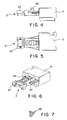
- Figures 4 and 5 are a side view and plan view, respectively of a short-circuit plug with a short-circuit insert pushed into a housing enveloping a plug according to an embodiment of the invention,
- Figure 6 shows a perspective view of the short-circuit insert pushed into the housing enveloping the plug,
- Figure 7 is a perspective view of the short-circuit plug of Figures 4, 5, and 6 showing a latch insert for securing the short-circuit insert in the housing enveloping the plug,
- Figures 8 to 10 are a side view, a plan view and a perspective view, respectively showing a short-circuit insert connected to an intermediate element, and
- Figures 11 to 13 are a side view, a plan view and a perspective view, respectively showing a short-circuit insert pushed into an alternative housing enveloping a plug according to another embodiment of the invention.
-
- A short-
circuit insert 2 according to an exemplary embodiment of the invention is shown in Figures 1 and 2. The short-circuit insert 2 has arectangular head region 27 with twoplug pillars 22 protruding out of it vertically to form aplug region 21. Theplug pillars 22 each have a substantially cylindrical contour and taper from a diameter which is slightly smaller than a height of thehead region 27 to a smaller diameter with respectively one or two raised latching rings 44, 45, wherein the first latching ring 44 provides a latching seat or shoulder 41 for latching the short-circuit insert in a plug recess of a corresponding plug housing 4 (shown in Figure 4.Optical fiber ends 26 are positioned at the end faces of theplug pillars 22. Optical fiber ends 26 in interact with corresponding counter-surfaces in theplug housing 4 to allow signal coupling or signal uncoupling respectively. - Primary securing of the short-circuit insert in the housing enveloping a
plug 4 is provided by first latching ring 44 at the right-hand plug pillar 22 (shown in Figure 2), which latching ring 44 can easily latch into a corresponding groove in the receiving region of the corresponding housing enveloping a plug. (Secondary securing comprises second latching rings 45 which are positioned at the same height on bothplug pillars 22.) The first latching ring 44 is provided for securing the short-circuit insert 2 against falling out of theplug housing 4, but does not prevent the short-circuit insert 2 being pulled out of theplug housing 4. - The short-
circuit insert 2 is prevented from being pulled out by a secondary securing means. In Figures 4, 5, 6, 11, 12 and 13, the second latching rings 45 grip theplug housing 4 to provide secondary securing. In Figures 8, 9 and 10,grooves 28 provide secondary securing. - In an exemplary embodiment of the invention, as shown in Figures 4, 5, 6, 11, 12 and 13, secondary securing is provided by interaction between second latching rings 45 and a latch insert 46 (shown in Figures 4 and 6). Latch
insert 46 is pushed into a receptacle 47 (shown in Figure 6) in theplug housing 4. When the short-circuit insert 2 is inserted into theplug housing 4, thelatch insert 46 engages behind the second latching rings 45 to prevent pulling the short-circuit insert 2 out of theplug housing 4. - In an alternative exemplary embodiment of the invention, as shown in Figures 8, 9 and 10, secondary securing is provided by interaction between the
grooves 28 and ametal spring 6 pushed over theplug housing 4. When the short-circuit insert 2 is pushed into the plug housing, thespring 6 engages with thegrooves 28 to prevent short-circuit insert 2 from being pulled out of theplug housing 4. - Referring again to Figures 4 through 7, - a short-
circuit insert 2 is shown pushed into aplug housing 4. Secondary securing of the short-circuit insert 2 is provided by thelatch insert 46 when it is pushed into the intendedreceptacle 47. Prior to fully pushing thelatch insert 46 into thereceptacle 47, the latch insert is slidingly aligned with thereceptacle 47. In Figures 4 through 6, the latch insert is not fully pushed into thereceptacle 47. In the fully pushed-in state, thelatch insert 46 can dip into thereceptacle 47 until flush with it. - The
plug housing 4 of Figures 4 to 6 with the short-circuit insert 2 installed forms the counter-piece (i.e., substitute) to a diagnostics plug of a diagnostic device (not shown). For this purpose, theplug housing 4 has a plug recess. With the diagnostic plug (not shown) of a ring bus (not shown) plugged-in to the plug recess of theplug housing 4, a largely damping-free signal transmission is possible from the optical fiber ends 26 to the optical fiber ends (not shown) of the diagnostics plug. - Figure 3 shows the short-
circuit insert 2 which has a curvedoptical fiber portion 23 inside acarrier element 29. Thisoptical fiber portion 23 runs inside theplug pillars 22 instraight portions 25 respectively, which are joined by anarc portion 24 located inside thehead region 27 of theplug insert 2. Thearc portion 24 describes a bend of 180 degrees such that the optical fiber ends 26 of thestraight portions 25 are disposed parallel to one another. - The
carrier element 29 of the short-circuit insert 2 can, for example, consist of injection-molded plastic into which theoptical fiber portion 23 is molded. Alternatively,, thecarrier element 29 can consist of two plastic housing halves which are bonded to one another or interlocked after insertion of theoptical fiber portion 23. - The
optical fiber portion 23 may, for example, consist of multi-component glass with cladding which previously was brought into the desired shape by means of heat, so that it is held free of stress in thecarrier element 29. It is a compact glass component that, if appropriate, may also comprise a coating with a lower refraction index. In a coated component, the damping at the 180°-bend is lower than in an uncoated component. Alternatively, a multi-conductor glass fiber (what is known as a multicore glass fiber) can be formed into theoptical fiber portion 23. The multi-conductor glass comprises a large number of fine single fibers being mechanically combined to form a fiber bundle. This means generally that the entire optical component consists of a plurality of individual glass fibers, each one of which preferably comprises its own coating which preferably consists of glass. The core of a glass fiber serves to conduct light. The refraction index of the coating is lower than the refraction index of the core and due to reflection at the core/coating interface it allows for efficient conducting of light within the core. - The fiber bundle and thus the multicore glass fiber may either be flexible or rigid. A rigid multicore glass fiber is obtained e.g. by sintering a plurality of glass fibers. A multicore glass fiber is preferred since the multicore glass fiber has lower damping values at the 180°-bend than the above-mentioned multi-component glass. Which of these embodiments of the
fiber portion 23 is used depends upon the desired application (i.e., the structure of the ring bus being short-circuited. The cladding serves to produce different refractive indices between the core and the sheath of the optical fiber so as to reduce the damping of transmitted signals due to undesired uncouplings. - The dimensions of
optical fiber portion 23 must provide optical coupling without significantly increasing damping. It is highly desirable to provide a small envelope to accommodate various applications in which space is limited. The inventors have determined that these goals can be achieved by controlling certain dimensions in the short-circuit insert 2. In an exemplary embodiment, the thickness of the optical fiber is about 1 mm, and the center distance between the optical fiber ends 26 is about. 6 mm. The total length of the short-circuit insert 2 is about 25 mm with thehead region 27 having a length and width, each of about. 5 mm. A typical diameter of theplug pillars 22 in thelower plug region 21 is about 3 mm. In the upper region, theplug pillars 22 can have a diameter approximately equivalent to the width of the head region 27 (approx. 5 mm). The resultant bending radius of thearc portion 24 of theoptical fiber portion 23 in thehead region 27 is a dimension of about 3 mm. With this bending radius, no significant signal damping will occur due to uncoupled light. - A preferred refractive index of the cladding glass is about. 1.6. A preferred refractive index of the core glass is about. 1.5. The diameters of the single fibers in a multicore optical fiber are preferably between about 30 and 70 µm and more preferably about 50 µm. The thickness of the cladding is preferably about. 3 µm. Signal damping in an optical fiber curved through 180 degrees which is built into a plug according to the invention is preferably less than 4 dB.
- An alternative connection of the short-
circuit insert 2 with aplug housing 4 is illustrated by reference to Figures 8 through 10. Such a connection is primarily intended for making a connection between conductors. An intermediate element can be pushed into theplug housing 4, in which intermediate element corresponding optical fiber ends (not shown) are embedded. These fiber ends are optically connected to the optical end surfaces 28 of the short-circuit insert 2. - Figures 11 to 13 show an inserted short-
circuit insert 2 in an alternative embodiment ofplug housing 4. The plug side here is capable of connection to a female connector and serves as a device place-holder. In this embodiment, the secondary securing is provided by thelatch insert 46 which is insertable into thereceptacle 47. Theplug housing 4 shown in these figures is preferably intended for recessed mounting.
Claims (16)
- An optical short-circuit insert, for accommodation in a plug housing , with a plug region (21) having two mutually parallel optical fiber ends (26) of an optical fiber portion (23) in which the optical fiber portion (23) is guided in an arc of 180 degrees, characterized in that the optical fiber portion (23) has a curved portion of a fiber comprising a multi-component glass core with cladding or a multi-core glass fiber with cladding enveloped in a plastic carrier (29).
- The optical short-circuit insert according to claim 1, characterized in that the plastic carrier (29) completely envelops the optical fiber (23) except for the optical end surfaces (26) and has one or more shoulders (41) for primary securing and secondary securing of the short-circuit insert (2) in a plug housing (4).
- The optical short-circuit insert according to claim 1 or 2, characterized in that the mutually parallel, straight portions (25) of the optical fiber portion (23) have a center distance of less than 10 mm.
- The optical short-circuit insert according to claim 1, 2 or 3, characterized in that the mutually parallel, straight portions (25) of the optical fiber portion (23) have a center distance of about. 6 mm.
- The optical short-circuit insert according to any one of claims 1 to 4, characterized in that the optical fiber portion (23) comprises a multi-component glass having a thickness of about. 1 mm.
- The optical short-circuit insert according to any one of claims 1 to 4, characterized in that the optical fiber portion (23) comprises a multi-conductor glass fiber having a thickness of about. 1 mm.
- The optical short-circuit insert according to any one of claims 1 to 4 characterized in that the optical fiber portion (23) comprises a multi-core glass fiber with cladding on each core.
- The optical short-circuit insert according to any one of claims 1 to 7 characterized in that the refractive index of the cladding is about 1.6 and the refractive index of the core is about 1.5.
- The optical short-circuit insert according to any one of claims 1 to 8 characterized in that the core has a diameter of between about 30 and 70 µm and the cladding has a thickness of about 3 µm.
- The optical short-circuit insert according to any one of claims 1 to 8 characterized in that the core has a diameter of about 50 µm and the cladding has a thickness of about 3 µm.
- An optical short-circuit plug having a plug housing enveloping a plug and a short-circuit insert according to any one of claims 1 to 9, which is received in the plug housing (4).
- The optical short-circuit plug according to claim 11, characterized in that the short circuit insert (2) has a primary securing mechanism (44) for securing the short-circuit insert (2) in the plug housing (4).
- The optical short-circuit plug according to either of claims 11 or 12, characterized in that the short-circuit insert (2) has secondary securing mechanism (45) for securing the short-circuit insert (2) in the plug housing (4).
- The optical short-circuit plug according to any one of claims 11 to 13, characterized in that the plug housing (4) has latching means for securing the optical short-circuit plug with a complementary plug connector.
- The optical short-circuit plug according to any one of claims 11 to 13, characterized in that the plug housing (4) is a socket connector.
- The optical short-circuit plug according to any one of claims 11 to 13, characterized in that the plug housing (4) is capable of being brought into a socket connector.
Applications Claiming Priority (2)
| Application Number | Priority Date | Filing Date | Title |
|---|---|---|---|
| DE10239924 | 2002-08-30 | ||
| DE10239924A DE10239924A1 (en) | 2002-08-30 | 2002-08-30 | Optical short circuit insert and optical short circuit plug |
Publications (2)
| Publication Number | Publication Date |
|---|---|
| EP1394583A1 true EP1394583A1 (en) | 2004-03-03 |
| EP1394583B1 EP1394583B1 (en) | 2011-06-22 |
Family
ID=31197512
Family Applications (1)
| Application Number | Title | Priority Date | Filing Date |
|---|---|---|---|
| EP03019339A Expired - Lifetime EP1394583B1 (en) | 2002-08-30 | 2003-08-27 | Optical short-circuit insert and optical short-circuit plug |
Country Status (6)
| Country | Link |
|---|---|
| US (1) | US7025508B2 (en) |
| EP (1) | EP1394583B1 (en) |
| JP (1) | JP2004094249A (en) |
| CN (1) | CN100362381C (en) |
| AT (1) | ATE514110T1 (en) |
| DE (1) | DE10239924A1 (en) |
Families Citing this family (5)
| Publication number | Priority date | Publication date | Assignee | Title |
|---|---|---|---|---|
| DE102004033388B4 (en) | 2003-07-24 | 2018-10-18 | Te Connectivity Germany Gmbh | Connector housing for optical fibers and method for its production |
| US7527435B2 (en) * | 2007-03-29 | 2009-05-05 | Corning Cable Systems Llc | Right-angle optical fiber connector assembly |
| TWM419932U (en) * | 2011-04-13 | 2012-01-01 | Xin Li | Multiplexing optical fiber jump connection box |
| DE102011106783A1 (en) * | 2011-07-06 | 2013-01-10 | Eads Deutschland Gmbh | Optical data transmission system |
| US11762149B1 (en) * | 2022-04-04 | 2023-09-19 | The United States Of America As Represented By The Secretary Of The Army | Fiber optic collimator with a beveled fiber endcap |
Citations (5)
| Publication number | Priority date | Publication date | Assignee | Title |
|---|---|---|---|---|
| DE2939231A1 (en) * | 1979-09-27 | 1981-04-02 | Siemens AG, 1000 Berlin und 8000 München | Multiple plug connector for optical glass fibres - has sockets with hold and guide discs with cylindrical spring in between in connector housing of two half shells |
| DE3544137A1 (en) * | 1985-12-13 | 1987-06-19 | Siemens Ag | Arrangement for direct feedback of transmit data as receive data in a communications device |
| US5944867A (en) * | 1994-11-24 | 1999-08-31 | Alcatel Fibres Optiques | Method of manufacturing a multi-core optical fiber |
| EP1096283A2 (en) * | 1999-10-25 | 2001-05-02 | Harting Automotive GmbH & Co. KG | Optical connector |
| EP1130436A1 (en) * | 2000-03-02 | 2001-09-05 | Mitel Semiconductor AB | Protective cover having a loopback function for an optical transceiver |
Family Cites Families (22)
| Publication number | Priority date | Publication date | Assignee | Title |
|---|---|---|---|---|
| US4418983A (en) * | 1981-03-16 | 1983-12-06 | Amp Incorporated | Optical waveguide connector |
| JPS61201633A (en) * | 1985-03-04 | 1986-09-06 | Sumitomo Electric Ind Ltd | Multi-core optical fiber manufacturing method |
| US4982083A (en) * | 1990-01-03 | 1991-01-01 | Amp Incorporated | Optical simulator with loop-back attenuator and filter |
| US4952798A (en) * | 1990-01-03 | 1990-08-28 | Amp Incorporated | Optical simulator with loop-back attenuator and optical thin film |
| US5076688A (en) * | 1990-03-23 | 1991-12-31 | Amp Incorporated | Optical simulator with loop-back attenuator having metalized optical fiber |
| US5039456A (en) * | 1990-03-23 | 1991-08-13 | Amp Incorporated | Method of molding an optical simulator |
| US5377293A (en) * | 1992-10-08 | 1994-12-27 | Olympus Optical Co., Ltd. | Optical fiber having multi-component core glass or a plastic core, and a coating layer |
| US5898813A (en) * | 1994-08-04 | 1999-04-27 | Siemens Aktiengesellschaft | Optical short-circuit plug |
| DE4428855C2 (en) * | 1994-08-04 | 1996-07-04 | Siemens Ag | Optical shorting plug |
| US5475781A (en) * | 1994-09-15 | 1995-12-12 | Chang; Peter C. | Optical fiber connector assembly with loop-back structure |
| US5892615A (en) * | 1997-03-17 | 1999-04-06 | Sdl, Inc. | Output power enhancement in optical fiber lasers |
| JP2000036346A (en) * | 1998-07-16 | 2000-02-02 | Sumitomo Wiring Syst Ltd | Connector for electric connections |
| US6454464B1 (en) * | 1998-12-28 | 2002-09-24 | Computer Crafts, Inc. | Fiber optic connectors and transceiver test devices |
| JP3065582U (en) * | 1999-05-26 | 2000-02-02 | 木谷電器株式会社 | Power connector for photovoltaic power generator |
| US6259830B1 (en) * | 1999-11-30 | 2001-07-10 | Corning, Incorporated | Poled electro-optic device and method |
| TW444919U (en) * | 2000-03-21 | 2001-07-01 | Shining Blick Enterprises Co | Improved terminal connecting structure of neon light conductive wire |
| US6439777B1 (en) * | 2000-05-15 | 2002-08-27 | Joseph C. Harrison | Fiber optic loop support |
| US6611648B2 (en) * | 2001-05-09 | 2003-08-26 | Corning Incorporated | Optical fibers having cores with different propagation constants, and methods of manufacturing same |
| US6558180B2 (en) * | 2001-05-18 | 2003-05-06 | Shimano Inc. | Waterproof electrical connector |
| US20030032321A1 (en) * | 2001-08-13 | 2003-02-13 | Tyco Electronics Corporation | Sealed connector |
| TW500227U (en) * | 2001-10-31 | 2002-08-21 | Hon Hai Prec Ind Co Ltd | Light attenuator with back-ring type fixation |
| US6634798B2 (en) * | 2001-11-26 | 2003-10-21 | Yu-Feng Cheng | Illuminating dust proof cap for an optical fiber socket |
-
2002
- 2002-08-30 DE DE10239924A patent/DE10239924A1/en not_active Withdrawn
-
2003
- 2003-08-25 CN CNB031549527A patent/CN100362381C/en not_active Expired - Fee Related
- 2003-08-27 AT AT03019339T patent/ATE514110T1/en active
- 2003-08-27 JP JP2003302946A patent/JP2004094249A/en active Pending
- 2003-08-27 EP EP03019339A patent/EP1394583B1/en not_active Expired - Lifetime
- 2003-08-28 US US10/651,137 patent/US7025508B2/en not_active Expired - Lifetime
Patent Citations (5)
| Publication number | Priority date | Publication date | Assignee | Title |
|---|---|---|---|---|
| DE2939231A1 (en) * | 1979-09-27 | 1981-04-02 | Siemens AG, 1000 Berlin und 8000 München | Multiple plug connector for optical glass fibres - has sockets with hold and guide discs with cylindrical spring in between in connector housing of two half shells |
| DE3544137A1 (en) * | 1985-12-13 | 1987-06-19 | Siemens Ag | Arrangement for direct feedback of transmit data as receive data in a communications device |
| US5944867A (en) * | 1994-11-24 | 1999-08-31 | Alcatel Fibres Optiques | Method of manufacturing a multi-core optical fiber |
| EP1096283A2 (en) * | 1999-10-25 | 2001-05-02 | Harting Automotive GmbH & Co. KG | Optical connector |
| EP1130436A1 (en) * | 2000-03-02 | 2001-09-05 | Mitel Semiconductor AB | Protective cover having a loopback function for an optical transceiver |
Non-Patent Citations (1)
| Title |
|---|
| LACY,A.E.: "Fiber Optics", PRENTICE HALL, USA, XP002260397 * |
Also Published As
| Publication number | Publication date |
|---|---|
| DE10239924A1 (en) | 2004-03-11 |
| US7025508B2 (en) | 2006-04-11 |
| EP1394583B1 (en) | 2011-06-22 |
| CN1492251A (en) | 2004-04-28 |
| ATE514110T1 (en) | 2011-07-15 |
| JP2004094249A (en) | 2004-03-25 |
| CN100362381C (en) | 2008-01-16 |
| US20040081407A1 (en) | 2004-04-29 |
Similar Documents
| Publication | Publication Date | Title |
|---|---|---|
| US5923805A (en) | Connector for plastic optical fiber | |
| US7128471B2 (en) | Single-use fiber optic cable | |
| CN102722003B (en) | Opto-electric connector | |
| EP2548062B1 (en) | Fiber optic interface devices for electronic devices | |
| US6422759B1 (en) | Fiber optic connector | |
| US7113679B2 (en) | Fiber optic drop cables and preconnectorized assemblies having toning portions | |
| EP1977279B1 (en) | Installation tool with integrated visual fault indicator for field-installable mechanical splice connector | |
| US7090407B2 (en) | Preconnectorized fiber optic drop cables and assemblies for efficient deployment | |
| EP2189831B1 (en) | Hybrid connector | |
| US5054879A (en) | Push/pull fiber optic connector | |
| US20060263011A1 (en) | Hybrid optical/electrical connector and adapter | |
| JPH04289805A (en) | Optical fiber connector device | |
| JP3285382B2 (en) | Conductor connecting device | |
| US6076974A (en) | Optical fiber connector | |
| CN111221082A (en) | Open-ended spring body for use in fiber optic connectors | |
| CN203825234U (en) | Field-assembleable mechanical splice connectors | |
| EP1394583B1 (en) | Optical short-circuit insert and optical short-circuit plug | |
| CA2357391A1 (en) | Adapter for coupling used with fiber optic connectors | |
| EP4644960A1 (en) | Optical fiber loopback assembly | |
| US20250277941A1 (en) | Loopback dust cap for fiber optic cable assembly and method of making same | |
| KR200157680Y1 (en) | Optical fiber splicer unity for multiple optical cable | |
| KR200150790Y1 (en) | Multicore optical connector | |
| KR200146324Y1 (en) | Multi-core optical splice assembly with alignment member fixing pin | |
| CN112799184A (en) | Double-fiber bidirectional tail fiber type digital optical transceiver module | |
| STANDARD | Four-Circuit Fiber Optic Connector |
Legal Events
| Date | Code | Title | Description |
|---|---|---|---|
| PUAI | Public reference made under article 153(3) epc to a published international application that has entered the european phase |
Free format text: ORIGINAL CODE: 0009012 |
|
| AK | Designated contracting states |
Kind code of ref document: A1 Designated state(s): AT BE BG CH CY CZ DE DK EE ES FI FR GB GR HU IE IT LI LU MC NL PT RO SE SI SK TR |
|
| AX | Request for extension of the european patent |
Extension state: AL LT LV MK |
|
| RAP1 | Party data changed (applicant data changed or rights of an application transferred) |
Owner name: SCHOTT GLAS Owner name: CARL-ZEISS-STIFTUNG TRADING AS SCHOTT GLAS Owner name: TYCO ELECTRONICS AMP GMBH |
|
| 17P | Request for examination filed |
Effective date: 20040827 |
|
| AKX | Designation fees paid |
Designated state(s): AT BE BG CH CY CZ DE DK EE ES FI FR GB GR HU IE IT LI LU MC NL PT RO SE SI SK TR |
|
| RAP1 | Party data changed (applicant data changed or rights of an application transferred) |
Owner name: TYCO ELECTRONICS AMP GMBH Owner name: SCHOTT AG |
|
| 17Q | First examination report despatched |
Effective date: 20050407 |
|
| GRAP | Despatch of communication of intention to grant a patent |
Free format text: ORIGINAL CODE: EPIDOSNIGR1 |
|
| GRAS | Grant fee paid |
Free format text: ORIGINAL CODE: EPIDOSNIGR3 |
|
| GRAA | (expected) grant |
Free format text: ORIGINAL CODE: 0009210 |
|
| AK | Designated contracting states |
Kind code of ref document: B1 Designated state(s): AT BE BG CH CY CZ DE DK EE ES FI FR GB GR HU IE IT LI LU MC NL PT RO SE SI SK TR |
|
| REG | Reference to a national code |
Ref country code: GB Ref legal event code: FG4D Ref country code: DE Ref legal event code: R081 Ref document number: 60337458 Country of ref document: DE Owner name: TE CONNECTIVITY GERMANY GMBH, DE Free format text: FORMER OWNERS: TYCO ELECTRONICS AMP GMBH, 64625 BENSHEIM, DE; SCHOTT GLAS, 55122 MAINZ, DE Ref country code: DE Ref legal event code: R081 Ref document number: 60337458 Country of ref document: DE Owner name: SCHOTT AG, DE Free format text: FORMER OWNERS: TYCO ELECTRONICS AMP GMBH, 64625 BENSHEIM, DE; SCHOTT GLAS, 55122 MAINZ, DE |
|
| REG | Reference to a national code |
Ref country code: CH Ref legal event code: EP |
|
| REG | Reference to a national code |
Ref country code: IE Ref legal event code: FG4D |
|
| REG | Reference to a national code |
Ref country code: DE Ref legal event code: R096 Ref document number: 60337458 Country of ref document: DE Effective date: 20110811 |
|
| REG | Reference to a national code |
Ref country code: NL Ref legal event code: VDEP Effective date: 20110622 |
|
| PG25 | Lapsed in a contracting state [announced via postgrant information from national office to epo] |
Ref country code: SE Free format text: LAPSE BECAUSE OF FAILURE TO SUBMIT A TRANSLATION OF THE DESCRIPTION OR TO PAY THE FEE WITHIN THE PRESCRIBED TIME-LIMIT Effective date: 20110622 |
|
| PG25 | Lapsed in a contracting state [announced via postgrant information from national office to epo] |
Ref country code: CY Free format text: LAPSE BECAUSE OF FAILURE TO SUBMIT A TRANSLATION OF THE DESCRIPTION OR TO PAY THE FEE WITHIN THE PRESCRIBED TIME-LIMIT Effective date: 20110622 Ref country code: FI Free format text: LAPSE BECAUSE OF FAILURE TO SUBMIT A TRANSLATION OF THE DESCRIPTION OR TO PAY THE FEE WITHIN THE PRESCRIBED TIME-LIMIT Effective date: 20110622 Ref country code: SI Free format text: LAPSE BECAUSE OF FAILURE TO SUBMIT A TRANSLATION OF THE DESCRIPTION OR TO PAY THE FEE WITHIN THE PRESCRIBED TIME-LIMIT Effective date: 20110622 Ref country code: GR Free format text: LAPSE BECAUSE OF FAILURE TO SUBMIT A TRANSLATION OF THE DESCRIPTION OR TO PAY THE FEE WITHIN THE PRESCRIBED TIME-LIMIT Effective date: 20110923 |
|
| REG | Reference to a national code |
Ref country code: SK Ref legal event code: T3 Ref document number: E 10068 Country of ref document: SK |
|
| PG25 | Lapsed in a contracting state [announced via postgrant information from national office to epo] |
Ref country code: NL Free format text: LAPSE BECAUSE OF FAILURE TO SUBMIT A TRANSLATION OF THE DESCRIPTION OR TO PAY THE FEE WITHIN THE PRESCRIBED TIME-LIMIT Effective date: 20110622 Ref country code: BE Free format text: LAPSE BECAUSE OF FAILURE TO SUBMIT A TRANSLATION OF THE DESCRIPTION OR TO PAY THE FEE WITHIN THE PRESCRIBED TIME-LIMIT Effective date: 20110622 |
|
| PG25 | Lapsed in a contracting state [announced via postgrant information from national office to epo] |
Ref country code: EE Free format text: LAPSE BECAUSE OF FAILURE TO SUBMIT A TRANSLATION OF THE DESCRIPTION OR TO PAY THE FEE WITHIN THE PRESCRIBED TIME-LIMIT Effective date: 20110622 Ref country code: PT Free format text: LAPSE BECAUSE OF FAILURE TO SUBMIT A TRANSLATION OF THE DESCRIPTION OR TO PAY THE FEE WITHIN THE PRESCRIBED TIME-LIMIT Effective date: 20111024 |
|
| PG25 | Lapsed in a contracting state [announced via postgrant information from national office to epo] |
Ref country code: RO Free format text: LAPSE BECAUSE OF FAILURE TO SUBMIT A TRANSLATION OF THE DESCRIPTION OR TO PAY THE FEE WITHIN THE PRESCRIBED TIME-LIMIT Effective date: 20110622 |
|
| REG | Reference to a national code |
Ref country code: HU Ref legal event code: AG4A Ref document number: E012334 Country of ref document: HU |
|
| PG25 | Lapsed in a contracting state [announced via postgrant information from national office to epo] |
Ref country code: MC Free format text: LAPSE BECAUSE OF NON-PAYMENT OF DUE FEES Effective date: 20110831 |
|
| REG | Reference to a national code |
Ref country code: CH Ref legal event code: PL |
|
| PLBE | No opposition filed within time limit |
Free format text: ORIGINAL CODE: 0009261 |
|
| STAA | Information on the status of an ep patent application or granted ep patent |
Free format text: STATUS: NO OPPOSITION FILED WITHIN TIME LIMIT |
|
| PG25 | Lapsed in a contracting state [announced via postgrant information from national office to epo] |
Ref country code: LI Free format text: LAPSE BECAUSE OF NON-PAYMENT OF DUE FEES Effective date: 20110831 Ref country code: CH Free format text: LAPSE BECAUSE OF NON-PAYMENT OF DUE FEES Effective date: 20110831 |
|
| REG | Reference to a national code |
Ref country code: FR Ref legal event code: ST Effective date: 20120430 |
|
| GBPC | Gb: european patent ceased through non-payment of renewal fee |
Effective date: 20110922 |
|
| REG | Reference to a national code |
Ref country code: IE Ref legal event code: MM4A |
|
| 26N | No opposition filed |
Effective date: 20120323 |
|
| PG25 | Lapsed in a contracting state [announced via postgrant information from national office to epo] |
Ref country code: IT Free format text: LAPSE BECAUSE OF FAILURE TO SUBMIT A TRANSLATION OF THE DESCRIPTION OR TO PAY THE FEE WITHIN THE PRESCRIBED TIME-LIMIT Effective date: 20110622 |
|
| PG25 | Lapsed in a contracting state [announced via postgrant information from national office to epo] |
Ref country code: DK Free format text: LAPSE BECAUSE OF FAILURE TO SUBMIT A TRANSLATION OF THE DESCRIPTION OR TO PAY THE FEE WITHIN THE PRESCRIBED TIME-LIMIT Effective date: 20110622 |
|
| REG | Reference to a national code |
Ref country code: DE Ref legal event code: R097 Ref document number: 60337458 Country of ref document: DE Effective date: 20120323 |
|
| PG25 | Lapsed in a contracting state [announced via postgrant information from national office to epo] |
Ref country code: IE Free format text: LAPSE BECAUSE OF NON-PAYMENT OF DUE FEES Effective date: 20110827 |
|
| PG25 | Lapsed in a contracting state [announced via postgrant information from national office to epo] |
Ref country code: FR Free format text: LAPSE BECAUSE OF NON-PAYMENT OF DUE FEES Effective date: 20110831 Ref country code: GB Free format text: LAPSE BECAUSE OF NON-PAYMENT OF DUE FEES Effective date: 20110922 |
|
| PG25 | Lapsed in a contracting state [announced via postgrant information from national office to epo] |
Ref country code: ES Free format text: LAPSE BECAUSE OF FAILURE TO SUBMIT A TRANSLATION OF THE DESCRIPTION OR TO PAY THE FEE WITHIN THE PRESCRIBED TIME-LIMIT Effective date: 20111003 |
|
| PG25 | Lapsed in a contracting state [announced via postgrant information from national office to epo] |
Ref country code: LU Free format text: LAPSE BECAUSE OF NON-PAYMENT OF DUE FEES Effective date: 20110827 |
|
| PG25 | Lapsed in a contracting state [announced via postgrant information from national office to epo] |
Ref country code: BG Free format text: LAPSE BECAUSE OF FAILURE TO SUBMIT A TRANSLATION OF THE DESCRIPTION OR TO PAY THE FEE WITHIN THE PRESCRIBED TIME-LIMIT Effective date: 20110922 |
|
| PG25 | Lapsed in a contracting state [announced via postgrant information from national office to epo] |
Ref country code: TR Free format text: LAPSE BECAUSE OF FAILURE TO SUBMIT A TRANSLATION OF THE DESCRIPTION OR TO PAY THE FEE WITHIN THE PRESCRIBED TIME-LIMIT Effective date: 20110622 |
|
| REG | Reference to a national code |
Ref country code: DE Ref legal event code: R082 Ref document number: 60337458 Country of ref document: DE Representative=s name: WILHELM & BECK, DE Ref country code: DE Ref legal event code: R081 Ref document number: 60337458 Country of ref document: DE Owner name: SCHOTT AG, DE Free format text: FORMER OWNERS: TYCO ELECTRONICS AMP GMBH, 64625 BENSHEIM, DE; SCHOTT AG, 55122 MAINZ, DE Ref country code: DE Ref legal event code: R081 Ref document number: 60337458 Country of ref document: DE Owner name: TE CONNECTIVITY GERMANY GMBH, DE Free format text: FORMER OWNERS: TYCO ELECTRONICS AMP GMBH, 64625 BENSHEIM, DE; SCHOTT AG, 55122 MAINZ, DE |
|
| REG | Reference to a national code |
Ref country code: AT Ref legal event code: HC Ref document number: 514110 Country of ref document: AT Kind code of ref document: T Owner name: SCHOTT AG, DE Effective date: 20160321 Ref country code: AT Ref legal event code: HC Ref document number: 514110 Country of ref document: AT Kind code of ref document: T Owner name: TE CONNECTIVITY GERMANY GMBH, DE Effective date: 20160321 |
|
| REG | Reference to a national code |
Ref country code: SK Ref legal event code: TC4A Ref document number: E 10068 Country of ref document: SK Owner name: SCHOTT AG, MAINZ, DE Effective date: 20160511 Ref country code: SK Ref legal event code: TC4A Ref document number: E 10068 Country of ref document: SK Owner name: TE CONNECTIVITY GERMANY GMBH, BENSHEIM, DE Effective date: 20160511 |
|
| PGFP | Annual fee paid to national office [announced via postgrant information from national office to epo] |
Ref country code: DE Payment date: 20180814 Year of fee payment: 16 |
|
| PGFP | Annual fee paid to national office [announced via postgrant information from national office to epo] |
Ref country code: CZ Payment date: 20180801 Year of fee payment: 16 Ref country code: AT Payment date: 20180725 Year of fee payment: 16 Ref country code: HU Payment date: 20180724 Year of fee payment: 16 Ref country code: SK Payment date: 20180712 Year of fee payment: 16 |
|
| REG | Reference to a national code |
Ref country code: DE Ref legal event code: R119 Ref document number: 60337458 Country of ref document: DE |
|
| REG | Reference to a national code |
Ref country code: AT Ref legal event code: MM01 Ref document number: 514110 Country of ref document: AT Kind code of ref document: T Effective date: 20190827 |
|
| PG25 | Lapsed in a contracting state [announced via postgrant information from national office to epo] |
Ref country code: HU Free format text: LAPSE BECAUSE OF NON-PAYMENT OF DUE FEES Effective date: 20190828 Ref country code: AT Free format text: LAPSE BECAUSE OF NON-PAYMENT OF DUE FEES Effective date: 20190827 |
|
| REG | Reference to a national code |
Ref country code: SK Ref legal event code: MM4A Ref document number: E 10068 Country of ref document: SK Effective date: 20190827 |
|
| PG25 | Lapsed in a contracting state [announced via postgrant information from national office to epo] |
Ref country code: SK Free format text: LAPSE BECAUSE OF NON-PAYMENT OF DUE FEES Effective date: 20190827 Ref country code: CZ Free format text: LAPSE BECAUSE OF NON-PAYMENT OF DUE FEES Effective date: 20190827 |
|
| PG25 | Lapsed in a contracting state [announced via postgrant information from national office to epo] |
Ref country code: DE Free format text: LAPSE BECAUSE OF NON-PAYMENT OF DUE FEES Effective date: 20200303 |