EP1394508A1 - Azimuth meter - Google Patents
Azimuth meter Download PDFInfo
- Publication number
- EP1394508A1 EP1394508A1 EP02726449A EP02726449A EP1394508A1 EP 1394508 A1 EP1394508 A1 EP 1394508A1 EP 02726449 A EP02726449 A EP 02726449A EP 02726449 A EP02726449 A EP 02726449A EP 1394508 A1 EP1394508 A1 EP 1394508A1
- Authority
- EP
- European Patent Office
- Prior art keywords
- magneto resistive
- magnetic field
- resistive elements
- coil
- azimuth meter
- Prior art date
- Legal status (The legal status is an assumption and is not a legal conclusion. Google has not performed a legal analysis and makes no representation as to the accuracy of the status listed.)
- Granted
Links
Images


Classifications
-
- G—PHYSICS
- G01—MEASURING; TESTING
- G01R—MEASURING ELECTRIC VARIABLES; MEASURING MAGNETIC VARIABLES
- G01R33/00—Arrangements or instruments for measuring magnetic variables
- G01R33/02—Measuring direction or magnitude of magnetic fields or magnetic flux
- G01R33/06—Measuring direction or magnitude of magnetic fields or magnetic flux using galvano-magnetic devices
- G01R33/09—Magnetoresistive devices
- G01R33/093—Magnetoresistive devices using multilayer structures, e.g. giant magnetoresistance sensors
-
- B—PERFORMING OPERATIONS; TRANSPORTING
- B82—NANOTECHNOLOGY
- B82Y—SPECIFIC USES OR APPLICATIONS OF NANOSTRUCTURES; MEASUREMENT OR ANALYSIS OF NANOSTRUCTURES; MANUFACTURE OR TREATMENT OF NANOSTRUCTURES
- B82Y25/00—Nanomagnetism, e.g. magnetoimpedance, anisotropic magnetoresistance, giant magnetoresistance or tunneling magnetoresistance
-
- G—PHYSICS
- G01—MEASURING; TESTING
- G01C—MEASURING DISTANCES, LEVELS OR BEARINGS; SURVEYING; NAVIGATION; GYROSCOPIC INSTRUMENTS; PHOTOGRAMMETRY OR VIDEOGRAMMETRY
- G01C17/00—Compasses; Devices for ascertaining true or magnetic north for navigation or surveying purposes
- G01C17/02—Magnetic compasses
- G01C17/28—Electromagnetic compasses
- G01C17/30—Earth-inductor compasses
Definitions
- the present invention relates to a flat azimuth meter or bearing sensor having a plane coil laminated with thin film magneto resistive elements (hereinafter referred to as “magneto resistive elements”) and to a small and light azimuth meter suitable for mobile devices.
- magneto resistive elements thin film magneto resistive elements
- an electric resistance in the current direction has a magneto-resistance effect, that is, it is reduced depending on a magnetic field strength.
- a relationship between the electric resistance (hereinafter referred to as "resistance") and the applied magnetic field strength can substantially be shown as in FIG. 20.
- Hk denotes a saturation magnetic field
- Hk denotes a saturation magnetic field
- An external magnetic field can be measured by using the linear relationship between the external magnetic field H and the resistance R when a certain biasing magnetic field is applied. Then, when each of two components orthogonal to each other of the earth magnetism is detected by two groups of magneto resistive elements that an appropriate bias is applied to, bearings can be measured at a measuring point.
- FIG. 22 is a schematic cross-sectional view thereof
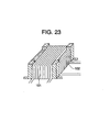
- FIG. 23 is a perspective view thereof.
- a +x-direction bias is applied by one bias coil 101 (referred to as an x-direction coil) to the four magneto resistive elements 91, 92, 93, and 94 constituting the MR bridge to measure an intermediate potential difference among the magneto resistive elements, and then, a -x - direction bias is applied by the same bias coil 101 to the magneto resistive elements to measure the intermediate potential difference among the magneto resistive elements.
- a difference between the intermediate potential differences measured when the +x-direction bias is applied and when the -x - direction bias is applied is proportional to sin ⁇ , the angle ⁇ being an angle between the horizontal component of the earth magnetism and the x-axis.
- a +y-direction bias is applied by the other bias coil 102 (referred to as a y-direction coil) to the four magneto resistive elements 91, 92, 93, and 94 constituting the MR bridge to measure an intermediate potential difference among the magneto resistive elements, and then, a -y-direction bias is applied by the same bias coil 102 to the magneto resistive elements to measure the intermediate potential difference among the magneto resistive elements.
- a difference between the intermediate potential differences measured when the +y-direction bias is applied and when the -y-direction bias is applied is proportional to sin( ⁇ /2- ⁇ ), that is, cos ⁇ .
- the saturation magnetic field is applied before the application of the biasing magnetic field in consideration of the hysteresis.
- the saturation magnetic field Hk is applied in +x direction, and then the intermediate potential difference between the magneto resistive elements is measured while applying the +x - direction biasing magnetic field Hb. Then, the saturation magnetic field -Hk is applied in -x direction by the same bias coil, and then the intermediate potential difference between the magneto resistive elements is measured while applying the -x - direction biasing magnetic field -Hb.
- the difference between the intermediate potential differences at the time of applications of the +x - direction bias and the -x - direction bias thus obtained is defined as an x - direction output Vx.
- the saturation magnetic field is applied in the +y direction by the other bias coil, and then the intermediate potential difference between the magneto resistive elements is measured while applying the +y - direction biasing magnetic field. Then, the saturation magnetic field is applied in the -y direction by the same bias coil, and then the intermediate potential difference between the magneto resistive elements is measured while applying the -y - direction biasing magnetic field.
- the difference between the intermediate potential differences at the time of applications of the +y - direction bias and the -y - direction bias thus obtained is defined as an y-direction output Vy. Based on the Vx and Vy, bearings are measured in the manner as described above.
- the orthogonal four magneto resistive elements assembled into the MR bridge described above may be formed as zigzag magneto resistive elements formed by etching a Ni-based alloy film deposited on a ceramic substrate.
- the magneto resistive elements can be quite small and thin.
- the azimuth meter has, at the smallest, a thickness of the order of 3 mm and an area of the order of 10 mm ⁇ 10 mm.
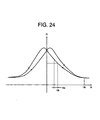
- the saturation magnetic field of the same direction as that of the biasing magnetic field is applied. After the application of the saturation magnetic field, application of the biasing magnetic field of the same direction tends to make the gradient of the curve for the resistance of the magneto resistive element, and the magnetic field be decreased, so that the output to be measured becomes low.
- An object of the present invention is to provide an azimuth meter or a bearing sensor of a significantly reduced thickness and area.
- Another object of the present invention is to provide an azimuth meter or a bearing sensor in which the number of applications of a current to a coil and the number of measurements are less than before.
- an azimuth meter comprises: a plane coil wound into a rectangular shape; and at least two groups of thin film magneto resistive elements disposed substantially parallel to the plane of the plane coil, in which each of said groups of magneto resistive elements constitutes an MR bridge of an even number of magneto resistive elements electrically connected to each other and detects and outputs two perpendicular components of the earth magnetism, and bearing information is obtained based on the output values, wherein the azimuth meter further comprises: means of passing a current in a predetermined direction through the plane coil to apply thereto a magnetic field that is equal to or higher than a saturation magnetization of said magneto resistive elements, applying a constant biasing magnetic field in the direction opposite to the direction, applying a magnetic field equal to or higher than the saturation magnetization of the magneto resistive elements in the direction opposite to said predetermined direction, and then applying a biasing magnetic field in the direction opposite to the latter direction; and means of passing a magnetic field measuring current through the groups of the thin film magneto
- a circuit is arranged so that, when one power supply is used to apply the magnetic field equal to or higher than the saturation magnetization of the magneto resistive elements, a discharge voltage of a capacitor having been previously charged by a shunt current from the power supply is superimposed to the voltage applied to the plane coil.
- an angle ⁇ formed between a longitudinal direction of each magneto resistive element and a side of the plane coil in the vicinity of the magneto resistive element satisfies a relation of sin ⁇ ⁇ cos ⁇ ⁇ 0, and an applied magnetic field characteristic in the vicinity of a region where the electrical resistance variation of the magneto resistive element in response to the applied magnetic field is the minimum is used.
- one of the groups of thin film magneto resistive elements is constituted by two pairs of magneto resistive elements, the magneto resistive elements in each pair being disposed intersecting opposite sides of said rectangular coil and being electrically connected to each other
- the other of the groups of thin film magneto resistive elements is constituted by two pairs of magneto resistive elements, the magneto resistive elements in each pair being disposed intersecting opposite sides, different from said sides, of said rectangular coil and being electrically connected to each other
- the longitudinal directions of two magneto resistive elements disposed on a same side are substantially perpendicular to each other.
- the angle ⁇ is any of about 45 degrees, about 135 degrees, about 225 degrees and about 315 degrees.
- the variation of the angle at which the longitudinal direction of each magneto resistive element intersects the side of the rectangular coil falls within a range of ⁇ 5 degrees.
- a circuit may be additionally provided which outputs a difference between an output obtained when a bias is applied in a positive direction and an output obtained when a bias is applied in a negative direction.
- a procedure of passing a current through the plane coil in a predetermined direction to apply thereto a magnetic field that is equal to or higher than a saturation magnetization of said magneto resistive elements, applying a constant biasing magnetic field in the opposite direction, and then measuring the resulting magnetic field to obtain an output value and a procedure of applying a magnetic field equal to or higher than the saturation magnetization of the magneto resistive elements in the direction opposite to said predetermined direction, applying a biasing magnetic field in the opposite direction, and then measuring the resulting magnetic field to obtain an output value may be performed two or more times, and the bearing information may be obtained based on the output values.
- an even number of magneto resistive elements are electrically connected to each other to constitute an MR bridge.
- magneto resistive elements A and B are disposed on opposite sides of a plane coil wound in a rectangular shape and connected in series
- a magneto resistive element C perpendicular to the magneto resistive element A is disposed on the same side as the magneto resistive element A
- a magneto resistive element D perpendicular to the magneto resistive element B is disposed on the same side as the magneto resistive element B
- the magneto resistive elements C and D are connected in series.
- the bridge is arranged to output a potential difference between an output V1 at the midpoint between the magneto resistive elements A and B and an output V2 at the midpoint between the magneto resistive elements C and D.
- two generally perpendicular components of the earth magnetism are detected by each of the groups of magneto resistive elements, and the bearing information is obtained based on the outputs thereof. This can reduce the effect of a hysteresis of an applied magnetic field on a resistance, eliminate the noise in the output and increase the absolute value of the output.
- FIG. 1 is a schematic plan view of EXAMPLE of the invention
- FIG. 2 is an exploded perspective view of EXAMPLE of the invention
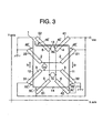
- FIG. 3 is an example of a circuit diagram of magneto resistive elements suitable for EXAMPLE of the invention.
- FIG. 4 is a graph showing a relationship between a resistance and an external magnetic field strength
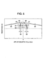
- FIG. 5 is an explanatory view of operation of magneto resistive elements according to the invention.
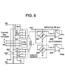
- FIG. 6 is an explanatory circuit diagram for driving the azimuth meter according to the invention.
- FIG. 7 is a timing chart of driving of the azimuth meter of the invention.
- FIG. 8 is graphs showing voltage wave and coil current wave of the driving circuit for the azimuth meter of the invention.
- FIG. 9 is a timing chart of driving of the azimuth meter of the invention.
- FIG. 10 is another circuit diagram for driving the azimuth meter according to the invention.
- FIG. 11 is a timing chart of driving of the azimuth meter of the invention.
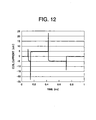
- FIG. 12 is a graph showing measured coil current wave of the azimuth meter of the invention.
- FIG. 13 is an enlarged graph showing measured coil current wave of the azimuth meter of the invention.
- FIG. 14 is another circuit diagram for driving the azimuth meter of the invention.
- FIG. 15 is a graph explaining circuit characteristics of the invention.
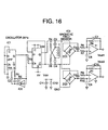
- FIG. 16 is a circuit diagram of analog output of the invention.
- FIG. 17 is another circuit diagram of analog output of the invention.
- FIG. 18 is a perspective view of a mobile phone with navigation installed with the azimuth meter of the invention.
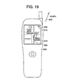
- FIG. 19 is a perspective view of a conventional mobile phone with navigation
- FIG. 20 is a typical graph explaining a relationship between an electric resistance and an applied magnetic field strength
- FIG. 21 is an explanatory circuit diagram of an MR bridge for a typical azimuth meter
- FIG. 22 is a schematic cross-sectional view of the MR bridge for the conventional azimuth meter
- FIG. 23 is a perspective view of the conventional azimuth meter.
- FIG. 24 is a graph showing a hysteresis involved in the relationship between the electric resistance and the applied magnetic field strength.
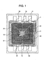
- FIG. 1 shows a plan view of an azimuth meter of EXAMPLE of the invention.
- reference numeral 1 denotes a tetragonal plane coil consisting of several tens of turns.
- the magneto resistive element pairs 2, 3, 4, and 5 are constituted by two magneto resistive elements 21 and 22, 31 and 32, 41 and 42, and 51 and 52, respectively.
- the longitudinal direction of the magneto resistive element 21 is substantially perpendicular to the longitudinal direction of the magneto resistive element 22, and each of these magneto resistive elements 21 and 22 is connected to the other at one terminal thereof (a terminal on the inner side of the plane coil 1 in this EXAMPLE).
- the longitudinal directions of the magneto resistive elements 31, 41, and 51 cross only the sides 12, 13, and 14, respectively, each of which is one side of the plane coil 1, and the longitudinal directions of the magneto resistive elements 32, 42, and 52 cross only the opposed sides 11, 14, and 13 of the plane coil 1, respectively, at an angle of about 45 degrees.
- the longitudinal directions of the magneto resistive elements 31, 41, and 51 are perpendicular to the longitudinal directions of their respective associated magneto resistive elements 32, 42, and 52.
- each of the magneto resistive elements 31 and 32 is connected to the other at one terminal thereof (a terminal on the inner side of the plane coil 1 in this EXAMPLE), each of the magneto resistive elements 41 and 42 is connected to the other at one terminal thereof (a terminal on the inner side of the plane coil 1 in this EXAMPLE), and each of the magneto resistive elements 51 and 52 is connected to the other at one terminal thereof (a terminal on the inner side of the plane coil 1 in this EXAMPLE). Furthermore, the longitudinal directions of the two magneto resistive elements 21 and 32 both crossing the side 11 of the plane coil 1 are perpendicular to each other.
- the longitudinal directions of the two magneto resistive elements 22 and 31 both crossing the side 12 are perpendicular to one another.
- the magneto resistive elements are provided on a substrate and further the plane coil is provided.
- the substrate is 0.7 mm thick.
- the thin film portion including the magneto resistive elements and plane coil disposed on the substrate is 40 to 50 micrometers thick.
- the substrate has a size of 3 mm ⁇ 4 mm.
- FIG. 2 is a schematic exploded perspective view thereof
- FIG. 3 is a circuit diagram thereof
- FIG. 6 is an explanatory circuit diagram for driving the azimuth meter according to the invention.
- FIG. 2 when a direct current is passed through the plane coil 1, a DC magnetic field is generated in a direction from the inside to the outside of the coil or vice versa in a plane parallel to the plane coil, so that the DC magnetic field is applied to the magneto resistive element pairs.
- the magneto resistive element crosses the side of the plane coil at an angle of 45 degrees as in the present invention, the external magnetic field is applied in a direction of 45 degrees with respect to a direction perpendicular to the longitudinal direction.
- the magneto resistive element has a shape magnetic anisotropy in the longitudinal direction, so that this situation can be considered to be equivalent to the situation in which a composite vector of the magnetic shape anisotropy magnetic field and the external magnetic field is applied thereto. Therefore, the relationship between the external magnetic field and the resistance when the external magnetic field is applied to the magneto resistive thin plate is represented by the graph shown in FIG. 4.
- FIG. 4 the relationship between the external magnetic field and the resistance when the external magnetic field is applied to the magneto resistive thin plate is represented by the graph shown in FIG. 4.
- the resistance has the minimum value while the applied magnetic field is negative, when a negative magnetic field of a predetermined strength is applied after a positive strong magnetic field is applied and reduced, the variation ratio of the resistance with respect to the variation in the applied magnetic field becomes the largest. In the case where while the strong magnetic field is applied in the negative direction and the applied magnetic field is gradually increased, the variation ratio of the resistance with respect to the variation in the applied magnetic field becomes the largest when a positive magnetic field of a predetermined strength is applied.
- a direct current is passed through the plane coil 1 in the clockwise direction in FIG. 3 to apply to the magneto resistive elements 21 to 52 a DC magnetic field enough to saturate a magnetic field of each of the magneto resistive elements 21 to 52 in the direction perpendicular to the longitudinal direction, and a direct current of a predetermined strength is passed through the plane coil 1 in the opposite direction (counterclockwise direction in FIG.
- the direct current is reduced or turned off, and a DC magnetic field caused by a direct current of a predetermined strength in a direction opposite to the direct current, in particular, counterclockwise direction in FIG. 3, that is, a magnetic field of a magnitude at which the variation ratio of the resistance with respect to the applied magnetic field approaches its maximum value is applied to take out an intermediate potential from the connected terminals of the magneto resistive elements.
- a DC magnetic field caused by a direct current of a predetermined strength in a direction opposite to the direct current, in particular, counterclockwise direction in FIG. 3 that is, a magnetic field of a magnitude at which the variation ratio of the resistance with respect to the applied magnetic field approaches its maximum value is applied to take out an intermediate potential from the connected terminals of the magneto resistive elements.
- the intermediate potential output of the magneto resistive elements 21 and 22 is represented by: Vcc ⁇ (1/2-1/(2 ⁇ Rb) ⁇ Hecos ⁇ ), where reference symbol ⁇ denotes a variation ratio of the resistance with respect to a magnetic field, and reference symbol Rb denotes a resistance of the magneto resistive element at the time when only the biasing magnetic field Hb is applied.
- a direct current is passed through the plane coil 1 in a direction opposite to that of the above description (counterclockwise direction in FIG. 3) to apply to the magneto resistive elements 21 to 52 a DC magnetic field enough to saturate a magnetic field of each of the magneto resistive elements 21 to 52 in the direction perpendicular to the longitudinal direction, and a direct current of a predetermined strength is passed through the plane coil 1 in a direction opposite to the former direct current (clockwise direction in FIG.
- the angle at which the magneto resistive thin plates cross the respective sides of the plane coil is assumed to be ⁇ /4, that is, 45 degrees
- bearings can be measured as far as the angle is more than 0 degree and not more than 60 degrees.
- the angle is too small, the region in which the resistance varies according to the magnetic field is reduced in the vicinity of the minimum value in FIG. 4 so that it is difficult to establish an appropriate biasing magnetic field. Therefore, the most manageable angle is 45 degrees.
- the cases has been described in which the longitudinal directions of the two magneto resistive elements crossing one side of the plane coil 1 are perpendicular to each other, and the longitudinal directions of the two magneto resistive elements of one magneto resistive element pair are perpendicular to each other, it is only needed that they are not parallel to each other.
- the most manageable angle thereof is a right angle. It is preferred that the angles at which the magneto resistive elements in one element pair cross the respective sides is in a mirror image relationship. As the relationship approximates the mirror image relationship, the output is less varied and approximates a sine wave.
- the difference between the angles at which the magneto resistive elements cross the respective sides falls within the range of +/- 5 degrees. More preferably, for all the magneto resistive elements in the azimuth meter, the variation in the angles at which the magneto resistive elements cross the respective sides falls within the range of +/- 5 degrees.
- the plane coil when the plane coil having an outer diameter of 2 to 3 mm and the number of turns of 50 to 100 turns was manufactured, a sufficient output was obtained.
- the size of the coil is preferably as small as possible to minimize the power consumption.
- the most effective way to generate a required magnetic field by a low power supply voltage is to reduce the resistance of the coil.
- the coil resistance depends on the thickness, width, and length, and the length dominantly depends on the size of the coil. While the width and thickness preferably are as large as possible, the thickness is defined by the space between the conductors. Within the restriction of the space between the conductors, the thickness is preferably large. In terms of manufacturing, however, it is not preferred that the plating thickness is too large. Therefore, the adequate thickness is 2 to 5 micrometers. Accordingly, the adequate width is 8 to 20 micrometers.
- the distance between the plane coil and the magneto resistive element is preferably as small as possible because the magnetic field in the extreme vicinity of the plane coil is used in the present invention. It is suitable that the distance is on the order of 1.5 times the thickness of the magneto resistive element and wiring film in consideration of the insulating property of the insulating film disposed therebetween. The adequate distance is 0.5 to 2 micrometers.
- the azimuth meter is of a two-layered type in which a magneto resistive element is provided on a substrate and a coil is disposed thereon.
- the number of the magneto resistive elements or the coils may be increased.
- a three-layered type is provided in which a magneto resistive element, a coil, and a magneto resistive element are disposed on a substrate sequentially, the output can be doubled.
- a three-layered type in which a coil, a magneto resistive element, and a coil are disposed on a substrate sequentially may be provided.
- the magneto resistive elements may be provided in a plurality of planes parallel to the plane in which the plane coil lies.
- a plane coil of parallelogram, rectangle or cross can be used.
- the present invention has been explained by using the plane coil of the square shape in the above description, a plane coil of other shape can be used.
- FIG. 4 is a graph showing a resistance of a magneto resistive element and an applied magnetic field at the time when the direction of a current forms an angle of 45 degrees with the direction of the applied magnetic field.
- the characteristic shown in this drawing is adopted.
- FIG. 5 is an explanatory view of operation of a magneto resistive element according to the invention.
- the gradients of the curve with respect to the applied magnetic field that is, the sensitivities, are larger than the gradient of the curve shown in FIG. 20. Therefore, applying the magnetic field at an angle of 45 degrees with respect to the longitudinal direction of the element (direction of the current in the element) can provide a high sensitivity. Operations at the points denoted by reference numerals are as follows.
- the resistance value 67 obtained when there is no external magnetic field the resistance changes between the values 66 and 68. This difference is denoted by a resistance value 69.
- Two of four magneto resistive elements connected in an MR-bridge configuration operate in this manner. The remaining two are disposed in the opposite direction with respect to the external magnetic field and can provide signals having the opposite sign to the resistance value 69 and the same magnitude as the resistance value 69.
- FIG. 6 shows an example of the driving circuit used in the invention.
- the rhombuses denote MR bridge circuits 201 and 202 constituted by four magneto resistive elements. Outputs thereof are amplified by CMOS operational amplifiers 203 and 204 about by a factor of 100. Given that a current passing through a plane coil 1 in a direction from a multiplexer Y terminal to a multiplexer X terminal is a positive current, FIG. 6 is associated with the timing chart shown in FIG. 7.
- FIG. 8 shows a voltage waveform and a coil current waveform for an actual circuit. The same operation can be attained if the midway operation is omitted. A timing chart in such a case is shown in FIG. 9.
- FIG. 10 shows a circuit improved to address the problem. While the arrangement following the MR bridges shown in FIG. 10 is the same as that shown in FIG. 6, the method of driving the coil is different from that for the circuit shown in FIG. 6.
- FIG. 11 shows a timing chart for explaining the operation thereof.
- the circuit shown in FIG. 6 requires two power supplies Vdd and Vee.
- the circuit shown in FIG. 10 is improved in this regard.
- the circuit is characterized in that a high voltage is obtained with a simple circuit arrangement by superimposing the voltages charged in the capacitors on the original voltage.
- the microcomputer is required to have two ports (A, B). While the port A is normally kept at the high level, it is turned to the low level when the sensor is used.
- the coil 1 is driven via four NOR gates (one IC), and the X terminal output serves as the ON/OFF output for power supply for the bridges 201, 202 and the operational amplifiers 203, 204.
- the manners of connection and operation are the same as in the circuit shown in FIG. 6.
- the input of the port B is kept at the low level. Then, the port A is also turned to the low level, thereby supplying electric power to the amplifiers and the bridges.
- the Y terminal side is turned to the low level and the Z terminal side is turned to the high level.
- a current flows through a resistor Rs2, the coil 1 and a resistor Rs1 to the Y terminal.
- a voltage is applied to the resistors Rs1, Rs2 and the coil 1.
- the capacitors are provided in a cross (bridge) arrangement between the Y and Z outputs, the sum of the absolute values of the magnitudes of the voltages of the capacitors is equal to or slightly higher than the power supply voltage.
- the input of the port B is turned to the high level. Then, the Y terminal output and the Z terminal output are both inverted. That is, the Y terminal is turned to the high level, and the Z terminal is turned to the low level.
- the plate of the capacitor C2 on the side of the resistor Rs2 connected to the Y terminal is additionally applied with the previously charged voltage, and thus, the capacitor C2 has a voltage about 1.5 times higher than the power supply voltage charged therein.
- the capacitor C1 connected to the Z terminal has a negative voltage about 0.5 times higher than the power supply voltage occurring therein.
- the coil 1 is applied with the differential voltage of the voltages, that is, a voltage about twice as high as the power supply voltage.
- the coil 1 can produce a sufficient magnetic field to provide a saturation magnetization of the magneto resistive elements.
- This state corresponds to the point 60 in FIG. 5.
- the capacitors completely discharge in about 2 ⁇ s, and then, a current flows through the coil in a direction from the Y terminal to the Z terminal.
- the value of the current is associated with the operating point 61 in FIG. 5, and is determined by the resistances of the resistors Rs1, Rs2 and the coil 1 and the power supply voltage.
- the capacitors C1 and C2 are charged in the direction opposite to that described above.
- the output voltages of the two MR bridges are amplified and measured. Once the measurement is completed, the input of the port B is turned to the low level.
- the Y terminal is turned to the low level, and the Z terminal is turned to the high level.
- the charges in the capacitors having been oppositely charged, produce a pulse current in the opposite direction.
- This state corresponds to the operating point 62 in FIG. 5.
- a current depending on the resistances of the resistors Rs1, Rs2 and the coil 1 flows through the coil 1 in a direction from the Z terminal to the Y terminal.
- the operating point 63 is reached.
- the outputs of the two MR bridges 201, 202 are measured again. Once the measurement is completed, the port A is returned to the high level.
- the circuit shown in FIG. 10 stops operating. After that, the differences between the two outputs for the magnetic fields in the two directions are determined, thereby providing measurements of the magnetic fields. Then, calculation is performed to provide a bearing indication.
- FIG. 12 shows measurements of an actual coil current.
- the significant positive and negative pulses correspond to the operating points 62 and 60 in FIG. 5.
- the flat positive and negative sections correspond to the operating points 61, 63.
- amplified analog voltages are measured for each direction four times in total.
- FIG. 13 is an enlarged graph showing the initial part of the coil current.
- the significant negative pulse corresponds to the point 60 in FIG. 5.
- the coli resistance is 200 ⁇
- the power supply voltage is 3 V
- a current of 23 mA is flows through the coil.
- the voltage applied to the coil is 4.6 V, which is higher than the power supply voltage.
- the pulse width can be changed by the capacitors C1 and C2.
- inversion of the IC output takes a long time.
- the charges in the capacitors flow through not only the coil, through which the current to be passed, but also through the resistors Rs1 and Rs2.
- the resistors Rs1 and Rs2 may be replaced with bidirectional constant-current elements, which don't increase the current even if the applied voltage increases.
- the circuit is arranged as shown in FIG. 14, and FIG. 15 shows a characteristic thereof.
- the junction-type field effect transistor used is the 2SK170, and the resistance is 33 ⁇ .
- the peak value of the current passing through the IC is 32 mA, while it is about 48 mA when the resistors Rs1 and Rs2 are used.
- FIGS. 16 and 17 shows exemplary circuits in the case where an analog output is required. These circuits are the same as the circuit described above in that the coil 1 is driven by the DFF (D-type flip flop) output via a bridge circuit constituted by capacitors C3, C4 and resistors R4, R5, and the operating points 60, 61, 62 and 63 in FIG. 5 are used. However, in this case, after the AD conversion, subtraction cannot be performed digitally, and thus, subtraction is performed in an analog manner.
- DFF D-type flip flop
- the DFF output is connected not only to the coil 1 for driving thereof but also to the MR bridges 201, 202, and inverted voltages are applied to the MR bridges 201, 202 so that when the MR bridges 201, 202 provide positive outputs at the operating point 61, a negative output is provided at the operating point 63.
- the MR bridges would provide no output.
- the MR bridges produces an offset voltage because of a slight difference between the resistances thereof.
- the reference point of the output voltage which is the average thereof, constitutes the midpoint of the power supply voltage, and accurate measurement can be attained.
- this state corresponds to the operating point 61, and thus, a voltage associated with the resistance level 68 is produced.
- the biasing magnetic field is inverted, resulting in the state of the operating point 63.
- the bridge voltage is also inverted, a voltage associated with the resistance level 66 occurs by being inverted.
- the MR bridge output constantly provides a negative voltage independently of the polarity of the voltage applied to the MR bridge, and the average value (integral value) thereof is also negative. In this way, an analog voltage continuously associated with the external magnetic field can be provided.
- the azimuth meter according to the invention can provide a mobile device, such as a mobile phone or PDA, with a particularly improved navigation function if it is mounted on the mobile device.
- a mobile device such as a mobile phone or PDA
- application software for displaying a town map such as a gourmet guide or hotel guide
- the map has been displayed with the actual bearing and the display screen being fixed.
- the upper edge of the display screen is associated with the north direction.
- the user has to rotate the display screen to direct the upper edge thereof to the north, and this is a burdensome procedure for the user.
- a mobile device with a navigation function such as a mobile phone, that can display the map by aligning the bearing of the map displayed on the screen with the actual geographical without regard to the orientation of the display screen of the mobile device.
- a component for detecting the elevation angle and a correction calculation circuit can be additionally provided.
- the azimuth meter may be a three-dimensional one to address the same.
- FIG. 18 is a perspective view of a mobile phone with a navigation function incorporating the azimuth meter according to the invention.
- Reference numeral 300 denotes a main unit of the mobile phone with a navigation function
- reference numeral 310 denotes a liquid crystal display (LCD) unit.
- LCD liquid crystal display
- FIG. 19 For comparison, a conventional example is shown in FIG. 19. Same parts as in those in FIG. 18 are assigned the same reference numerals. The position of the user is indicated by a cross mark 320.
- the mobile phone with a navigation function according to the invention shown in FIG. 18 can display a map by aligning an actual bearing 400 with a map bearing 350. This is achieved by using the bearing information obtained by the incorporated azimuth meter according to the invention.
- no small azimuth element can be incorporated in the mobile phone, and thus, the map bearing 350 indicating the north is fixed on a display screen 315 and is not aligned with the actual bearing 400.
- the plane coil is used to apply the saturation magnetic field and biasing magnetic field to the magneto resistive elements, the coil can be made of a thin film, and therefore, the thickness and are of the azimuth meter can be reduced.
- bearings can be measured by applying biasing magnetic fields in x and y directions simultaneously, so that the number of measurements of bearings can be halved compared to a conventional technique.
- the output can be increased.
Landscapes
- Physics & Mathematics (AREA)
- Engineering & Computer Science (AREA)
- Remote Sensing (AREA)
- Radar, Positioning & Navigation (AREA)
- General Physics & Mathematics (AREA)
- Nanotechnology (AREA)
- Chemical & Material Sciences (AREA)
- Environmental & Geological Engineering (AREA)
- Life Sciences & Earth Sciences (AREA)
- Geology (AREA)
- Electromagnetism (AREA)
- General Life Sciences & Earth Sciences (AREA)
- Condensed Matter Physics & Semiconductors (AREA)
- Crystallography & Structural Chemistry (AREA)
- Measuring Magnetic Variables (AREA)
- Hall/Mr Elements (AREA)
Abstract
Description
Claims (8)
- An azimuth meter, comprising: a plane coil wound into a shape symmetrical with respect to two axes perpendicular to each other; and at least two groups of thin film magneto resistive elements disposed substantially parallel to the plane of the plane coil, in which each of said groups of magneto resistive elements constitutes an MR bridge of an even number of magneto resistive elements electrically connected to each other and detects and outputs two perpendicular components of the earth magnetism, and bearing information is obtained based on the output values, wherein the azimuth meter further comprises: means of passing a current in a predetermined direction through the plane coil to apply thereto a magnetic field that is equal to or higher than a saturation magnetization of said magneto resistive elements, applying a constant biasing magnetic field in the opposite direction, applying a magnetic field equal to or higher than the saturation magnetization of the magneto resistive elements in the direction opposite to said predetermined direction, and then applying a biasing magnetic field in the opposite direction; and means of passing a magnetic field measuring current through the groups of the thin film magneto resistive elements concurrently with the applications of said biasing magnetic fields.
- The azimuth meter according to claim 1, wherein a circuit is arranged so that, when a power supply voltage is used to apply the magnetic field equal to or higher than the saturation magnetization of the magneto resistive elements, a discharge voltage of a capacitor having been previously charged by a shunt current from the power supply is superimposed to the voltage applied to the plane coil.
- The azimuth meter according to claim 1, wherein the plane coil has a rectangular shape, an angle β formed between a longitudinal direction of each magneto resistive element and a side of the plane coil intersecting the magneto resistive element satisfies a relation of sinβ × cosβ ≠ 0, and an applied magnetic field characteristic in the vicinity of a region where the electrical resistance variation of the magneto resistive element in response to the applied magnetic field is the minimum is used.
- The azimuth meter according to claim 3, wherein one of the groups of thin film magneto resistive elements is constituted by two pairs of magneto resistive elements, the magneto resistive elements in each pair being disposed intersecting opposite sides of said rectangular coil and being electrically connected to each other, the other of the groups of thin film magneto resistive elements is constituted by two pairs of magneto resistive elements, the magneto resistive elements in each pair being disposed intersecting opposite sides, different from said sides, of said rectangular coil and being electrically connected to each other, and the longitudinal directions of two magneto resistive elements disposed on a same side are substantially perpendicular to each other.
- The azimuth meter according to claim 3, wherein the angle β is any of about 45 degrees, about 135 degrees, about 225 degrees and about 315 degrees.
- The azimuth meter according to claim 2, wherein the variation of the angle at which the longitudinal direction of each magneto resistive element intersects the side of the rectangular coil falls within a range of ±5 degrees.
- The azimuth meter according to claim 1, in which the two perpendicular components of the earth magnetism are detected by each of the groups of magneto resistive elements and output therefrom, and the bearing information is obtained based on the output values, wherein a circuit is additionally provided which outputs a difference between an output obtained when a bias is applied in a positive direction and an output obtained when a bias is applied in a negative direction.
- The azimuth meter according to claim 1, wherein a procedure of passing a current through the plane coil in a predetermined direction to apply thereto a magnetic field that is equal to or higher than a saturation magnetization of said magneto resistive elements, applying a constant biasing magnetic field in the opposite direction, and then measuring the resulting magnetic field to obtain an output value and a procedure of applying a magnetic field equal to or higher than the saturation magnetization of the magneto resistive elements in the direction opposite to said predetermined direction, applying a biasing magnetic field in the opposite direction, and then measuring the resulting magnetic field to obtain an output value are performed two or more times, and the bearing information is obtained based on the output values.
Applications Claiming Priority (3)
| Application Number | Priority Date | Filing Date | Title |
|---|---|---|---|
| JP2001153068 | 2001-05-22 | ||
| JP2001153068A JP4006674B2 (en) | 2001-05-22 | 2001-05-22 | Compass |
| PCT/JP2002/004909 WO2002095330A1 (en) | 2001-05-22 | 2002-05-21 | Azimuth meter |
Publications (3)
| Publication Number | Publication Date |
|---|---|
| EP1394508A1 true EP1394508A1 (en) | 2004-03-03 |
| EP1394508A4 EP1394508A4 (en) | 2008-09-10 |
| EP1394508B1 EP1394508B1 (en) | 2011-09-14 |
Family
ID=18997645
Family Applications (1)
| Application Number | Title | Priority Date | Filing Date |
|---|---|---|---|
| EP02726449A Expired - Lifetime EP1394508B1 (en) | 2001-05-22 | 2002-05-21 | Azimuth meter |
Country Status (7)
| Country | Link |
|---|---|
| US (1) | US6826842B2 (en) |
| EP (1) | EP1394508B1 (en) |
| JP (1) | JP4006674B2 (en) |
| KR (1) | KR100846078B1 (en) |
| CN (1) | CN100367001C (en) |
| CA (1) | CA2447711C (en) |
| WO (1) | WO2002095330A1 (en) |
Cited By (1)
| Publication number | Priority date | Publication date | Assignee | Title |
|---|---|---|---|---|
| WO2004083780A1 (en) * | 2003-03-19 | 2004-09-30 | Casio Computer Co., Ltd. | Azimuth measuring method and apparatus, and recording medium storing the azimuth measuring method |
Families Citing this family (24)
| Publication number | Priority date | Publication date | Assignee | Title |
|---|---|---|---|---|
| JP2005114489A (en) * | 2003-10-06 | 2005-04-28 | Citizen Electronics Co Ltd | Magnetic orientation detector |
| US7436184B2 (en) | 2005-03-15 | 2008-10-14 | Pathfinder Energy Services, Inc. | Well logging apparatus for obtaining azimuthally sensitive formation resistivity measurements |
| US7414405B2 (en) | 2005-08-02 | 2008-08-19 | Pathfinder Energy Services, Inc. | Measurement tool for obtaining tool face on a rotating drill collar |
| JP4302089B2 (en) * | 2005-10-19 | 2009-07-22 | 三菱重工業株式会社 | Crankcase integrated cylinder block |
| JP4904052B2 (en) * | 2005-12-27 | 2012-03-28 | アルプス電気株式会社 | Magnetic orientation detector |
| US7990139B2 (en) * | 2006-05-17 | 2011-08-02 | Hitachi Metals, Ltd. | Two-axis geo-magnetic field sensor with elimination of eefect of external offset magnetic fields |
| JP2008192645A (en) * | 2007-01-31 | 2008-08-21 | Tdk Corp | Thin film magnetic device and manufacturing method thereof |
| KR100887952B1 (en) * | 2007-07-10 | 2009-03-11 | (주)애니캐스팅 | Slide device for mobile communication terminal |
| US7558675B2 (en) | 2007-07-25 | 2009-07-07 | Smith International, Inc. | Probablistic imaging with azimuthally sensitive MWD/LWD sensors |
| US8600115B2 (en) | 2010-06-10 | 2013-12-03 | Schlumberger Technology Corporation | Borehole image reconstruction using inversion and tool spatial sensitivity functions |
| US9658360B2 (en) | 2010-12-03 | 2017-05-23 | Schlumberger Technology Corporation | High resolution LWD imaging |
| IT1403409B1 (en) * | 2010-12-20 | 2013-10-17 | St Microelectronics Srl | POLARIZATION CIRCUIT FOR A MAGNETIC FIELD SENSOR, AND ITS POLARIZATION METHOD |
| IT1403433B1 (en) | 2010-12-27 | 2013-10-17 | St Microelectronics Srl | MAGNETORESISTIVE SENSOR WITH REDUCED PARASITE CAPACITY, AND METHOD |
| IT1403434B1 (en) * | 2010-12-27 | 2013-10-17 | St Microelectronics Srl | MAGNETIC FIELD SENSOR WITH ANISOTROPIC MAGNETORESISTIVE ELEMENTS, WITH PERFECT ARRANGEMENT OF RELATIVE MAGNETIZATION ELEMENTS |
| JP2012173206A (en) | 2011-02-23 | 2012-09-10 | Yamanashi Nippon Denki Kk | Magnetic sensor and manufacturing method thereof |
| DE102011080050B4 (en) * | 2011-07-28 | 2014-10-23 | Horst Siedle Gmbh & Co. Kg | Electrical circuit, in particular for a revolution counter |
| US9372242B2 (en) * | 2012-05-11 | 2016-06-21 | Memsic, Inc. | Magnetometer with angled set/reset coil |
| JP6430565B2 (en) * | 2016-03-23 | 2018-11-28 | アナログ・デヴァイシズ・グローバル | Magnetic field detector |
| DE102017129346A1 (en) * | 2016-12-13 | 2018-06-14 | Infineon Technologies Ag | Magnetic sensor circuits and systems and methods of forming magnetic sensor circuits |
| WO2018173590A1 (en) * | 2017-03-23 | 2018-09-27 | 日本電産株式会社 | Magnetic sensor unit and magnetic field direction detection method using same |
| US10739165B2 (en) | 2017-07-05 | 2020-08-11 | Analog Devices Global | Magnetic field sensor |
| CN107631722B (en) * | 2017-09-08 | 2021-01-08 | 维沃移动通信有限公司 | Calibration method of electronic compass and mobile terminal |
| CN109061528B (en) * | 2018-08-02 | 2020-08-18 | 华中科技大学 | Three-axis planar magnetic sensor based on giant magneto-impedance effect |
| JP7024811B2 (en) * | 2019-12-11 | 2022-02-24 | Tdk株式会社 | Magnetic field detector and current detector |
Family Cites Families (20)
| Publication number | Priority date | Publication date | Assignee | Title |
|---|---|---|---|---|
| CA1126818A (en) * | 1978-03-27 | 1982-06-29 | Hiroyuki Ohkubo | Apparatus for sensing an external magnetic field |
| IT1211140B (en) * | 1980-12-09 | 1989-09-29 | Sony Corp | MAGNETIC SENSOR SWITCH DEVICE. |
| DE3370875D1 (en) * | 1982-07-26 | 1987-05-14 | Landis & Gyr Ag | Magnetic field sensor and the use thereof |
| JP3318762B2 (en) * | 1991-12-03 | 2002-08-26 | カシオ計算機株式会社 | Electronic compass |
| US5644851A (en) * | 1991-12-20 | 1997-07-08 | Blank; Rodney K. | Compensation system for electronic compass |
| JP3316689B2 (en) * | 1992-03-03 | 2002-08-19 | カシオ計算機株式会社 | Electronic compass |
| JPH05322575A (en) * | 1992-05-18 | 1993-12-07 | Casio Comput Co Ltd | Electronic azimuth meter |
| JPH06174471A (en) * | 1992-12-10 | 1994-06-24 | Casio Comput Co Ltd | Electronic compass |
| US5435070A (en) * | 1993-07-26 | 1995-07-25 | Honeywell Inc. | Simplified compass with multiple segment display capability |
| EP0742906B1 (en) * | 1994-01-31 | 1998-09-23 | Fraunhofer-Gesellschaft zur Förderung der angewandten Forschung e.V. | Use of a miniaturized planar-design coil assembly for the detection of ferromagnetic materials |
| JP2655106B2 (en) * | 1994-12-07 | 1997-09-17 | 日本電気株式会社 | Magnetoresistive sensor |
| JPH08201061A (en) * | 1995-01-31 | 1996-08-09 | Shimadzu Corp | Thin film magnetic sensor |
| JPH08233576A (en) * | 1995-02-28 | 1996-09-13 | Sony Corp | Magnetic sensor |
| JP3277752B2 (en) * | 1995-05-10 | 2002-04-22 | 松下電器産業株式会社 | Orientation sensor |
| JPH09311167A (en) * | 1996-05-22 | 1997-12-02 | Sumitomo Metal Mining Co Ltd | Magnetic / magnetic direction sensor and magnetic / magnetic direction measuring method |
| US6166539A (en) * | 1996-10-30 | 2000-12-26 | Regents Of The University Of Minnesota | Magnetoresistance sensor having minimal hysteresis problems |
| EP0855599A3 (en) * | 1997-01-24 | 2001-05-02 | Siemens Aktiengesellschaft | Electronic compass |
| DE69925573T2 (en) | 1999-05-12 | 2006-04-27 | Asulab S.A. | Magnetic feeler made on a semiconductive substrate |
| EP1052519B1 (en) * | 1999-05-12 | 2005-06-01 | Asulab S.A. | Magnetic detector made on a semiconductive substrate |
| JP3573100B2 (en) * | 2001-02-06 | 2004-10-06 | 日立金属株式会社 | Compass and direction measurement method |
-
2001
- 2001-05-22 JP JP2001153068A patent/JP4006674B2/en not_active Expired - Fee Related
-
2002
- 2002-05-21 CN CNB028090357A patent/CN100367001C/en not_active Expired - Fee Related
- 2002-05-21 WO PCT/JP2002/004909 patent/WO2002095330A1/en not_active Ceased
- 2002-05-21 US US10/474,131 patent/US6826842B2/en not_active Expired - Fee Related
- 2002-05-21 EP EP02726449A patent/EP1394508B1/en not_active Expired - Lifetime
- 2002-05-21 KR KR1020037015068A patent/KR100846078B1/en not_active Expired - Fee Related
- 2002-05-21 CA CA002447711A patent/CA2447711C/en not_active Expired - Fee Related
Cited By (1)
| Publication number | Priority date | Publication date | Assignee | Title |
|---|---|---|---|---|
| WO2004083780A1 (en) * | 2003-03-19 | 2004-09-30 | Casio Computer Co., Ltd. | Azimuth measuring method and apparatus, and recording medium storing the azimuth measuring method |
Also Published As
| Publication number | Publication date |
|---|---|
| WO2002095330A1 (en) | 2002-11-28 |
| CA2447711C (en) | 2009-04-28 |
| CA2447711A1 (en) | 2002-11-28 |
| KR20040008183A (en) | 2004-01-28 |
| EP1394508A4 (en) | 2008-09-10 |
| CN100367001C (en) | 2008-02-06 |
| US20040111906A1 (en) | 2004-06-17 |
| US6826842B2 (en) | 2004-12-07 |
| CN1531642A (en) | 2004-09-22 |
| JP2002350136A (en) | 2002-12-04 |
| JP4006674B2 (en) | 2007-11-14 |
| EP1394508B1 (en) | 2011-09-14 |
| KR100846078B1 (en) | 2008-07-14 |
Similar Documents
| Publication | Publication Date | Title |
|---|---|---|
| EP1394508B1 (en) | Azimuth meter | |
| EP2413153B1 (en) | Magnetic detection device | |
| JP3465059B2 (en) | Magnetic field sensor comprising magnetization reversal conductor and one or more magnetoresistive resistors | |
| JP5044070B2 (en) | Magnetic field detection device | |
| US9970997B2 (en) | Magnetic field sensing apparatus and magnetic field sensing module | |
| JP3573100B2 (en) | Compass and direction measurement method | |
| JP2008209311A (en) | Magnetometric sensor, magnetic azimuth sensor, magnetic field detection method, and magnetic azimuth detection method | |
| Ripka et al. | Micro-fluxgate sensor with closed core | |
| US7886600B2 (en) | Motion sensor and portable telephone using the same | |
| US10901050B2 (en) | Magnetic field sensing device including magnetoresistor wheatstone bridge | |
| US20200300943A1 (en) | Magnetic field sensing device | |
| JP2016145745A (en) | Magnetic sensor | |
| JP2003028941A (en) | Magnetism-measuring method and magnetometric-sensor drive circuit | |
| CN100510624C (en) | Magnetism detecting device and electronic azimuth meter using the same | |
| JP3496655B2 (en) | Compass | |
| JPH10170619A (en) | Magnetic sensor and alternating bias magnetic field impressing method therefor | |
| JP7244157B1 (en) | Magnetic sensor and magnetic detection method | |
| JP3528813B2 (en) | Compass and direction measurement method | |
| JP2576136B2 (en) | Magnetic direction measurement device | |
| JP3316689B2 (en) | Electronic compass | |
| JP2012093267A (en) | Current detector | |
| Marien et al. | A6. 1-Magnetic Microsensors: Quo Vadis? | |
| JP2008527370A (en) | Angle sensor | |
| NL8303305A (en) | Thin film magnetometer - with thin ferromagnetic film and coil etc. providing alternating auxiliary field with a component in the plane of film |
Legal Events
| Date | Code | Title | Description |
|---|---|---|---|
| PUAI | Public reference made under article 153(3) epc to a published international application that has entered the european phase |
Free format text: ORIGINAL CODE: 0009012 |
|
| 17P | Request for examination filed |
Effective date: 20031205 |
|
| AK | Designated contracting states |
Kind code of ref document: A1 Designated state(s): BE DE DK ES FI FR GB GR IT LU NL PT SE TR |
|
| A4 | Supplementary search report drawn up and despatched |
Effective date: 20080812 |
|
| 17Q | First examination report despatched |
Effective date: 20090826 |
|
| GRAP | Despatch of communication of intention to grant a patent |
Free format text: ORIGINAL CODE: EPIDOSNIGR1 |
|
| GRAS | Grant fee paid |
Free format text: ORIGINAL CODE: EPIDOSNIGR3 |
|
| GRAA | (expected) grant |
Free format text: ORIGINAL CODE: 0009210 |
|
| AK | Designated contracting states |
Kind code of ref document: B1 Designated state(s): DE NL |
|
| REG | Reference to a national code |
Ref country code: DE Ref legal event code: R096 Ref document number: 60241026 Country of ref document: DE Effective date: 20111201 |
|
| REG | Reference to a national code |
Ref country code: NL Ref legal event code: T3 |
|
| PLBE | No opposition filed within time limit |
Free format text: ORIGINAL CODE: 0009261 |
|
| STAA | Information on the status of an ep patent application or granted ep patent |
Free format text: STATUS: NO OPPOSITION FILED WITHIN TIME LIMIT |
|
| 26N | No opposition filed |
Effective date: 20120615 |
|
| REG | Reference to a national code |
Ref country code: DE Ref legal event code: R097 Ref document number: 60241026 Country of ref document: DE Effective date: 20120615 |
|
| PGFP | Annual fee paid to national office [announced via postgrant information from national office to epo] |
Ref country code: DE Payment date: 20150512 Year of fee payment: 14 |
|
| PGFP | Annual fee paid to national office [announced via postgrant information from national office to epo] |
Ref country code: NL Payment date: 20150409 Year of fee payment: 14 |
|
| REG | Reference to a national code |
Ref country code: DE Ref legal event code: R119 Ref document number: 60241026 Country of ref document: DE |
|
| REG | Reference to a national code |
Ref country code: NL Ref legal event code: MM Effective date: 20160601 |
|
| PG25 | Lapsed in a contracting state [announced via postgrant information from national office to epo] |
Ref country code: NL Free format text: LAPSE BECAUSE OF NON-PAYMENT OF DUE FEES Effective date: 20160601 |
|
| PG25 | Lapsed in a contracting state [announced via postgrant information from national office to epo] |
Ref country code: DE Free format text: LAPSE BECAUSE OF NON-PAYMENT OF DUE FEES Effective date: 20161201 |