EP1394392A1 - Throttle control apparatus with vibration insulator - Google Patents
Throttle control apparatus with vibration insulator Download PDFInfo
- Publication number
- EP1394392A1 EP1394392A1 EP03019495A EP03019495A EP1394392A1 EP 1394392 A1 EP1394392 A1 EP 1394392A1 EP 03019495 A EP03019495 A EP 03019495A EP 03019495 A EP03019495 A EP 03019495A EP 1394392 A1 EP1394392 A1 EP 1394392A1
- Authority
- EP
- European Patent Office
- Prior art keywords
- motor
- throttle
- engine
- throttle body
- vibration
- Prior art date
- Legal status (The legal status is an assumption and is not a legal conclusion. Google has not performed a legal analysis and makes no representation as to the accuracy of the status listed.)
- Granted
Links
- 239000012212 insulator Substances 0.000 title claims abstract description 73
- 229920005989 resin Polymers 0.000 claims description 28
- 239000011347 resin Substances 0.000 claims description 28
- 229910052782 aluminium Inorganic materials 0.000 claims description 3
- XAGFODPZIPBFFR-UHFFFAOYSA-N aluminium Chemical compound [Al] XAGFODPZIPBFFR-UHFFFAOYSA-N 0.000 claims description 3
- 229920001971 elastomer Polymers 0.000 abstract description 10
- 239000000806 elastomer Substances 0.000 abstract description 10
- 238000000465 moulding Methods 0.000 description 12
- 238000003780 insertion Methods 0.000 description 11
- 230000037431 insertion Effects 0.000 description 9
- 230000003014 reinforcing effect Effects 0.000 description 6
- 210000000078 claw Anatomy 0.000 description 5
- 229910052751 metal Inorganic materials 0.000 description 5
- 239000002184 metal Substances 0.000 description 5
- XEEYBQQBJWHFJM-UHFFFAOYSA-N Iron Chemical compound [Fe] XEEYBQQBJWHFJM-UHFFFAOYSA-N 0.000 description 4
- 239000003086 colorant Substances 0.000 description 4
- 229920002943 EPDM rubber Polymers 0.000 description 2
- 239000005062 Polybutadiene Substances 0.000 description 2
- 230000003247 decreasing effect Effects 0.000 description 2
- 229910052742 iron Inorganic materials 0.000 description 2
- 229920002857 polybutadiene Polymers 0.000 description 2
- 229920005749 polyurethane resin Polymers 0.000 description 2
- 239000004925 Acrylic resin Substances 0.000 description 1
- 230000001133 acceleration Effects 0.000 description 1
- 230000005540 biological transmission Effects 0.000 description 1
- 238000002485 combustion reaction Methods 0.000 description 1
- 238000002788 crimping Methods 0.000 description 1
- 238000004512 die casting Methods 0.000 description 1
- 239000003292 glue Substances 0.000 description 1
- 238000009434 installation Methods 0.000 description 1
- 238000009413 insulation Methods 0.000 description 1
- 238000004519 manufacturing process Methods 0.000 description 1
- 239000000155 melt Substances 0.000 description 1
- 238000012986 modification Methods 0.000 description 1
- 230000004048 modification Effects 0.000 description 1
- 230000000149 penetrating effect Effects 0.000 description 1
- 230000002093 peripheral effect Effects 0.000 description 1
- 239000004814 polyurethane Substances 0.000 description 1
- 238000007789 sealing Methods 0.000 description 1
- 229920002379 silicone rubber Polymers 0.000 description 1
- 239000004945 silicone rubber Substances 0.000 description 1
Images


Classifications
-
- F—MECHANICAL ENGINEERING; LIGHTING; HEATING; WEAPONS; BLASTING
- F02—COMBUSTION ENGINES; HOT-GAS OR COMBUSTION-PRODUCT ENGINE PLANTS
- F02D—CONTROLLING COMBUSTION ENGINES
- F02D11/00—Arrangements for, or adaptations to, non-automatic engine control initiation means, e.g. operator initiated
- F02D11/06—Arrangements for, or adaptations to, non-automatic engine control initiation means, e.g. operator initiated characterised by non-mechanical control linkages, e.g. fluid control linkages or by control linkages with power drive or assistance
- F02D11/10—Arrangements for, or adaptations to, non-automatic engine control initiation means, e.g. operator initiated characterised by non-mechanical control linkages, e.g. fluid control linkages or by control linkages with power drive or assistance of the electric type
-
- F—MECHANICAL ENGINEERING; LIGHTING; HEATING; WEAPONS; BLASTING
- F02—COMBUSTION ENGINES; HOT-GAS OR COMBUSTION-PRODUCT ENGINE PLANTS
- F02D—CONTROLLING COMBUSTION ENGINES
- F02D41/00—Electrical control of supply of combustible mixture or its constituents
- F02D41/02—Circuit arrangements for generating control signals
- F02D41/04—Introducing corrections for particular operating conditions
- F02D41/10—Introducing corrections for particular operating conditions for acceleration
- F02D41/102—Switching from sequential injection to simultaneous injection
-
- F—MECHANICAL ENGINEERING; LIGHTING; HEATING; WEAPONS; BLASTING
- F16—ENGINEERING ELEMENTS AND UNITS; GENERAL MEASURES FOR PRODUCING AND MAINTAINING EFFECTIVE FUNCTIONING OF MACHINES OR INSTALLATIONS; THERMAL INSULATION IN GENERAL
- F16K—VALVES; TAPS; COCKS; ACTUATING-FLOATS; DEVICES FOR VENTING OR AERATING
- F16K1/00—Lift valves or globe valves, i.e. cut-off apparatus with closure members having at least a component of their opening and closing motion perpendicular to the closing faces
- F16K1/16—Lift valves or globe valves, i.e. cut-off apparatus with closure members having at least a component of their opening and closing motion perpendicular to the closing faces with pivoted closure-members
- F16K1/18—Lift valves or globe valves, i.e. cut-off apparatus with closure members having at least a component of their opening and closing motion perpendicular to the closing faces with pivoted closure-members with pivoted discs or flaps
- F16K1/22—Lift valves or globe valves, i.e. cut-off apparatus with closure members having at least a component of their opening and closing motion perpendicular to the closing faces with pivoted closure-members with pivoted discs or flaps with axis of rotation crossing the valve member, e.g. butterfly valves
-
- F—MECHANICAL ENGINEERING; LIGHTING; HEATING; WEAPONS; BLASTING
- F02—COMBUSTION ENGINES; HOT-GAS OR COMBUSTION-PRODUCT ENGINE PLANTS
- F02D—CONTROLLING COMBUSTION ENGINES
- F02D11/00—Arrangements for, or adaptations to, non-automatic engine control initiation means, e.g. operator initiated
- F02D11/06—Arrangements for, or adaptations to, non-automatic engine control initiation means, e.g. operator initiated characterised by non-mechanical control linkages, e.g. fluid control linkages or by control linkages with power drive or assistance
- F02D11/10—Arrangements for, or adaptations to, non-automatic engine control initiation means, e.g. operator initiated characterised by non-mechanical control linkages, e.g. fluid control linkages or by control linkages with power drive or assistance of the electric type
- F02D2011/101—Arrangements for, or adaptations to, non-automatic engine control initiation means, e.g. operator initiated characterised by non-mechanical control linkages, e.g. fluid control linkages or by control linkages with power drive or assistance of the electric type characterised by the means for actuating the throttles
- F02D2011/102—Arrangements for, or adaptations to, non-automatic engine control initiation means, e.g. operator initiated characterised by non-mechanical control linkages, e.g. fluid control linkages or by control linkages with power drive or assistance of the electric type characterised by the means for actuating the throttles at least one throttle being moved only by an electric actuator
-
- F—MECHANICAL ENGINEERING; LIGHTING; HEATING; WEAPONS; BLASTING
- F02—COMBUSTION ENGINES; HOT-GAS OR COMBUSTION-PRODUCT ENGINE PLANTS
- F02D—CONTROLLING COMBUSTION ENGINES
- F02D2200/00—Input parameters for engine control
- F02D2200/60—Input parameters for engine control said parameters being related to the driver demands or status
- F02D2200/602—Pedal position
-
- Y—GENERAL TAGGING OF NEW TECHNOLOGICAL DEVELOPMENTS; GENERAL TAGGING OF CROSS-SECTIONAL TECHNOLOGIES SPANNING OVER SEVERAL SECTIONS OF THE IPC; TECHNICAL SUBJECTS COVERED BY FORMER USPC CROSS-REFERENCE ART COLLECTIONS [XRACs] AND DIGESTS
- Y02—TECHNOLOGIES OR APPLICATIONS FOR MITIGATION OR ADAPTATION AGAINST CLIMATE CHANGE
- Y02T—CLIMATE CHANGE MITIGATION TECHNOLOGIES RELATED TO TRANSPORTATION
- Y02T10/00—Road transport of goods or passengers
- Y02T10/10—Internal combustion engine [ICE] based vehicles
- Y02T10/40—Engine management systems
Definitions
- the present invention is related to a throttle control apparatus of an engine to control opening of a throttle valve, which is rotatably supported on a throttle body, by driving a motor corresponding to a manipulation of a driver.
- a throttle control apparatus controls opening of a throttle valve to a designated opening by driving a motor corresponding to degree of stepping an accelerator pedal by a driver.
- Degree of stepping of the accelerator pedal is detected by an accelerator position sensor to supply current to the motor corresponding to the signal.
- the throttle valve driven by the motor is opened and closed to control the air intake flow to the engine.
- the motor rotates the shaft of the throttle valve via a drive train such as reduction gears.
- the motor is accommodated in a motor case integrally molded with a throttle body rotatably supporting the shaft of the throttle valve.
- the motor is screwed and is fixed on the motor case at its mounting flange disposed on one end of the motor housing by mounting bolts or clamp screws. (For example, refer to Japanese Patent Application Publications No. 10-252510, and 10-131772.)
- vibration of an engine is transmitted to the throttle body directly.
- components such as the motor and the gears are made to be highly rigid to endure the vibration.
- FIG. 6 such an assembling work is necessary that attachment of a vibration insulative leaf spring 103 between the bottom side of a motor case 104 and the opposing surface of a motor 102 by press-insertion or the like.
- the vibration insulative leaf spring 103 is to avoid transmitting of the engine vibration to the motor 102 via a throttle body 101.
- a motor mounting flange need to be screwed and fixed.
- the motor mounting flange and the motor housing are formed integrally.
- the wall thickness of the motor housing is increased.
- the weight of the motor unit is increased.
- the motor vibrates intensely, thus, engagement can cause failure between a gear of a motor spindle and a reduction gear.
- An armature inside the motor vibrates intensely, and the motor shaft tends to fail to rotate.
- the objective of the present invention is to propose a vibration insulating throttle apparatus without increase of components and reduction of assembling workability.
- a vibration insulator is formed integrally to suppress vibration transferred from the engine to the throttle body.
- a joint section is integrally molded with the throttle body and is connected with an intake manifold. Near the joint section, a vibration insulator is disposed to suppress the vibration. Thus, an additional vibration insulator need not be built in the throttle. To reduce components, preferably, the vibration insulator is integrally formed with the joint section.
- An airtight seal section between the sidewall of the engine and the mounting flange of the throttle body is integrally formed with the vibration insulator to reduce sealing members.
- the vibration insulator is integrally formed with the throttle body, which rotatably supports the shaft of the throttle valve and accommodates the motor.
- a motor holder is integrally formed with the throttle body to lock the motor. Nearby the motor holder, the vibration insulator is disposed to suppress the vibration. Thus, additional insulative spring or the like need not be built in the motor by press-insertion or the like.
- An elastically deformable snap hook is disposed on a motor case or is disposed on a motor cover to support the motor. Then, the motor can be fixed by elastic force of the vibration insulator and the snap hook. Thus, mounting bolts and clamp screws for screwing the motor mounting flange to the motor case is not needed. Furthermore, the motor mounting flange need not be integrally formed with the motor housing. Therefore, weight of the motor unit can be reduced.
- the motor case is integrally molded with resin on the side wall of the bore section of the throttle body.
- the throttle body is integrally molded with heatproof resin or metal or is aluminum die-cast, and the vibration insulator is integrally molded with elastically deformable heatproof resin on the throttle body, so that the number of components can be reduced comparing with attaching of an additional vibration insulator to the throttle body.
- the number of components can be decreased and assembling workability can be improved so that cost can be reduced.
- a throttle control apparatus of an engine comprises a motor 1, which structures an actuator; reduction gears (13, 14, 15), which decelerate the rotation speed of the motor 1 by a predetermined reduction ratio; a throttle valve 2, which is driven to rotate by the motor 1 via the reduction gears; a throttle body 5, which rotatably supports a shaft 3 (spindle section, valve shaft) of the throttle valve 2 via a ball bearing 4 and rigidly accommodates the motor 1; a sensor cover 6, which encloses the opening side of the throttle body 5; and an engine control apparatus (engine control unit: ECU), which controls the rotation speed of the engine by driving of the motor 1 corresponding to the manipulation degree by a driver (the stepping degree of an accelerator pedal) so that the opening of the throttle valve 2 is controlled to corresponding opening degree.
- an air intake passage 70 is formed to connect an air intake passage 30 formed in the throttle body 5 and a combustion chamber of each cylinder of the engine.
- an accelerator position sensor (not shown) is wired with the ECU.
- the accelerator position sensor converts the stepping degree of the accelerator pedal by the driver into electric signals (accelerator position signals), and transmits the accelerator position signals to the ECU.
- the throttle control apparatus has a throttle position sensor (not shown) to convert the opening of the throttle valve 2 into an electric signals (throttle opening signals) and to transmit the throttle opening signals of the throttle valve 2 to the ECU.
- the ECU is structured to perform feedback control (PID control: proportional integral differential control) for the motor 1 to eliminate the deviation between the throttle opening signal from the throttle position sensor and the accelerator position signal from the accelerator position sensor.
- PID control proportional integral differential control
- the sensor cover 6 is made of electrically insulative resin to insulate each external connection terminals of the throttle position sensor and each power supply terminal for the motor 1.
- the sensor cover 6 has a concave sensor holder 11 to rigidly lock the throttle position sensor.
- the motor 1 is a driving source, and has plural permanent magnets, armature core, armature coils and so on in the motor housing.
- the reduction gears have a pinion gear 13 fixed to the outer periphery of the power spindle 12 of the motor 1; an intermediate reduction gears 14, which rotate as engaging with the pinion gear 13; and a rotation member (rotor core) 15 which rotates as engaging with the intermediate reduction gears 14.
- the intermediate reduction gears 14 are integrally molded with metal or resin, and are rotatably fixed on the outer periphery of a supporting shaft 16 which is a rotation center.
- the intermediate reduction gears 14 have a large diameter gear 14a engaging the pinion gear 13 and a small diameter gear 14b engaging the reduction gear 15a of the rotation member 15.
- the pinion gear 13 and the intermediate reduction gears 14 are rotation power transmission means to transmit rotation power of the motor 1 to the reduction gear 15a of the rotation member 15.
- the rotation member 15 is formed in a predetermined approximately ring-shape with metal.
- the reduction gear 15a is formed to engage with the small-diameter gear 14b of the intermediate reduction gears 14.
- permanent magnets (not shown) are bonded with glue or the like opposing against the outer periphery of the throttle position sensor.
- a through-hole is formed in the center of the rotation member 15.
- the right end section of a reinforcing member 24 (described below) in FIG. 1A penetrates the through-hole. Subsequently, the right end section of the reinforcing member 24 in FIG.
- the throttle valve 2 is a butterfly-type rotary valve to control intake air flow fed into the engine.
- the throttle valve 2 comprises the first semicircular plate section 21 extended from the top end surface of the shaft 3 upward in FIG. 1A and the second semicircular plate section 22 extended from the bottom end surface of the shaft 3 downward in FIG. 1A.
- the shaft 3 has a cylindrical resinous molded section 23 integrally molded with heatproof resin and the reinforcing member (metallic center core member) 24 to reinforce the resinous molded section 23.
- the throttle body 5 which is integrally molded with heatproof resin, structures a part of an engine air intake pipe connecting with the engine intake manifold 10, and rotatably supports the throttle valve 2.
- This throttle body 5 has an annular bore wall section 33. Inside of the bore wall section 33, approximately circular air intake passage 30, in which intake air flows to the engine, is formed.
- a first cylindrical shaft bush 31, and a second cylindrical shaft bush 32 and a cylindrical bearing holder 34 are disposed.
- the second cylindrical shaft bush 32 rotatably supports the first supported section and the second supported section of the shaft 3.
- the cylindrical bearing holder 34 rotatably supports the second supported section of the shaft 3 via the ball bearing 4.
- a first circular shaft through-hole 41 and a second circular shaft through-hole 42 are formed so that the shaft 3 of the throttle valve 2 passes through.
- a plug 39 is fit to block the opening of the first shaft bush 31.
- containershaped gear case 35 is integrally formed with heatproof resin to rotatably accommodate the rotation member 15 including the reduction gear 15a.
- a sensor cover 6 made of highly electrically insulative resin, is disposed at the opening side of the gear case 35. In the internal space formed between the gear case 35 and the sensor cover 6, the reduction gears are rotatably accommodated
- engine joint sections (mounting flange, mount section on the engine, installation section on the engine) 36 are integrally molded with heatproof resin so that the engine joint sections 36 radially extends.
- the throttle body 5 is mounted on a joint end face 71 of the engine intake manifold 10 with clamping members such as plural clamp bolts 72 and plural washers 73 or the like.
- clamping members such as plural clamp bolts 72 and plural washers 73 or the like.
- the engine joint sections 36 radially extend outward from outer periphery of the bore wall section 33.
- a flange vibration insulator 7 is integrally formed with resin (two colored molding) to enhance vibration insulation property of the throttle body 5.
- a motor holder 37 is integrally formed with heatproof resin to lock the motor 1.
- the motor holder 37 internally has a bottomed cylindrical motor case 51 to accommodate the motor 1, a motor cover 52 to plug the opening side of the motor case 51, and a bottom vibration insulator 8 and a ceiling vibration insulator 9 to enhance vibration-proof property of the motor 1.
- detent claws On the motor case 51, plural detent claws (snap hooks) 53 are formed to accommodate and to support the motor 1 and the motor cover 52.
- the detent claws 53 are hooked on right side end of the motor cover 52 in FIG. 1B by its elastically deformable section as penetrating plural insertion holes 54 formed in the motor cover 52.
- trough-holes 55, 56 are formed so that the power spindle 12 of the motor 1 penetrates the trough-holes 55, 56.
- the motor cover 52 can be fixed on the opening side of the motor case 51.
- the flange vibration insulators 7, the bottom vibration insulator 8 and the ceiling vibration insulator 9 are integrally formable with the heatproof resinous member of the throttle body 5, and are made of elastically deformable heatproof elastomer.
- AS the heatproof elastomer for example, high density nytril butadiene rubber (H-NBR), nytril butadiene rubber (NBR), silicone rubber, ethylene propylene diene monomer (EPDM), acrylate resin, poly urethane resin (PUR), elastomer and so on can be used.
- the flange vibration insulator 7 is integrally formed with resin (molded in two colors) on the engine joint section 36 of the throttle body 5, and has an approximately ring-shaped bolt seat 61 on which the head section of the clamp bolts 72 contacts; a cylindrical section 62 extended from the bolt seat 61 downward in FIG. 2; and annular section 63 extended in the radial direction of the bore wall section 33 from the lower end section of the cylindrical section 62 in FIG. 2 and contacting the joint face 71 of the engine intake manifold 10, and so on.
- a ring-shaped seal section 64 is formed between the engine joint section 36 and the joint end face 71 of the intake manifold 10 to avoid leakage of intake air.
- insertion hole 62a is internally formed so that the shaft of the clamp bolt 72 is inserted into the insertion hole 62a.
- the bottom vibration insulator 8 is integrally formed with resin (molded in two colors) on the left side end face of the motor case 51 in FIG. 1B (motor mounting face, bottom face).
- the ceiling vibration insulator 9 is insert-molded on the left side end face of the motor cover 52 in FIG. 1B (motor mounting face, top face).
- a resin molding dies including a sliding die to mold the air intake passage 30 (refer to FIG. 2) and a sliding die, which is for molding the first shaft through-hole 41 and the second shaft through-hole 42
- heat-melt heatproof resin is injected from one or two or more gates, and inside of the cavity of the molding die is formed with heatproof resin.
- the heatproof resinous member filled in the molding die is taken out, cooled and hardened (solidified), or the heatproof resinous member is cooled and hardened (solidified) in the molding dies.
- a resinous molded member is formed including the first shaft bush 31; the second shaft bush 32; the bore wall section 33; the bearing holder 34; the gear case 35; the engine joint section 36 and the motor holder 37.
- the bottom vibration insulator 8 is integrated with the resinous molded member to be the throttle body 5 molded in two colors.
- the ceiling vibration insulator 9 is also molded in two colors to be integrated with the motor cover 52 in the same manner as the bottom vibration insulator 8. (Or, the ceiling vibration insulator 9 is bonded to the motor cover 52. )
- the motor 1 is attached in the motor case 51 of the throttle body 5.
- the motor cover 52 with the bottom vibration insulator 9 is attached so that the power spindle 12 of the motor 1 penetrates the through-hole 55, 56. Then, as the plural insertion holes 54 formed in the motor cover 52 are penetrated by the plural detent claws 53 formed on the motor case 51, the motor cover 52 is attached on the opening side of the motor case 51.
- the left end section of the motor 1 in FIG. 1B receives elastic force from the bottom vibration insulator 8 added on the bottom face of the motor case 51
- the right end section of the motor 1 in FIG. 1A receives elastic force from the ceiling vibration insulator 9 added on the ceiling face of the motor cover 52.
- the motor cover 52 presses the motor 1 via the ceiling vibration insulator 9.
- the motor cover 52 is pushed back by reactive force of the bottom vibration insulator 8 and the ceiling vibration insulator 9, and is held by the plural detent claws 53.
- vibration-proof property of the motor 1 locked between the motor holder 37, that is the bottom face of the motor case 51 (the motor mounting face), and the ceiling face of the motor cover 52 (the motor mounting face) can be enhanced.
- accelerator position signals from the accelerator position sensor are input to the ECU.
- the motor 1 shown in FIG. 1 is energized, and the power spindle 12 of the motor 1 rotates so that opening of the throttle valve 2 becomes a designated opening degree.
- the pinion gear 13 rotates.
- the rotation power is transmitted to the large diameter gear 14a of the intermediate reduction gears 14.
- the rotation member 15 rotates with its reduction gear 15a being engaged with the small diameter gear 14b.
- the rotation member 15 rotates with the shaft 3, and the shaft 3 rotates by designated angle so that the throttle valve 2 is kept in designated angle in the air intake passage 30 formed in the throttle body 5 toward the engine.
- the flange vibration insulator 7 made of heatproof elastomer and the engine joint section 36 of the throttle body 5, which is integrally formed with heatproof resin, are screwed with the plural clamp bolts 72 onto the joint end face 71 of the engine intake manifold 10.
- the flange vibration insulator 7 added on the engine joint section 36 of the throttle body 5 engine vibration transferred from the engine intake manifold 10 can be absorbed.
- vibration of the throttle body 5 can be suppressed.
- vibration-proof property of the entire throttle control apparatus can be improved.
- the motor 1 is locked between the motor holder 37 and the motor cover 52.
- the engine vibration can be transferred to the motor holder 37.
- vibration of the motor 1 can be suppressed and the motor 1 does not vibrate largely so that vibration-proof property of the motor 1 can be enhanced.
- engagement incomplete between the pinion gear 13 disposed on the power spindle 12 and the large diameter gear 14a of the intermediate reduction gears 14 does not occur.
- the rotation power of the motor 1 can be stably transmitted to the throttle valve 2 and its shaft 3.
- the opening of the throttle valve 2 is set to aimed angle so that the intake air flow to the engine becomes desired rate.
- the controllability of the opening of the throttle valve 2 by the throttle control apparatus can be enhanced so that engine rotation speed corresponding to the degree of stepping the accelerator pedal can be obtained.
- the flange vibration insulator 7 need not be independently assembled between the mounting flange face 46 of the engine joint section 36 and the joint end face 71 of the engine intake manifold 10.
- the flange vibration insulator 7 need not be independently assembled on the bolt flange face 44 and on the insertion hole 45 of the engine joint face 36 of the throttle body 5.
- the motor cover 52 is pushed back by the reactive force of pushing of the ceiling vibration insulator 9, and is held by the plural detent claws 53 integrally formed on the motor case 51.
- bolts and screws for locking the motor 1 on the motor holder 37 are not necessary.
- the number of the components is decreased, and assembling workability can be improved. Therefore, cost can be reduced, and productivity can be improved.
- each engine joint section 36 of the throttle body 5 in each engine joint section 36 of the throttle body 5, the bolt flange face 44; the insertion hole 45 in which the clamp bolt 72 passes through; and the mounting flange 46 corresponding to the joint end face 71 of the engine intake manifold 10 are formed.
- the insertion hole 45 is formed so that its inner diameter of the lower end side (the engine side) is formed larger than that of the upper end side (opposite side of the engine) in FIG. 4.
- plural cylindrical vibration insulators 7 flange vibration insulators
- resin two colored molding
- Each flange vibration insulator 7 is molded with resin in each metallic cylindrical reinforcing member 65 made of iron or the like in order to avoid buckling deformation or the like of the engine joint section 36 by the axial force of the clamp bolts 72. That is, each reinforcing member 65 integrated with the flange vibration insulator 7 is insert-molded in the heatproof resinous member which forms the engine joint section 36. From the lower end of the flange vibration insulator 7 in FIG. 4, a ring-shaped seal section 64 is formed to protrude toward lower direction in FIG. 4 to avoid leakage of intake air from between the throttle body 5 and the joint end face 71 of the intake manifold 10.
- the throttle body 5 made of heatproof resin and engine joint section 36 made of metallic plate are separately formed. Before mounting the throttle body 5 on the joint end face 71 of the engine intake manifold 10 (refer to FIG. 2), the throttle body 5 and the engine joint section 36 made of metallic plate are integrated.
- the engine joint section 36 has the bolt flange face 44, the insertion hole 45 and the mounting flange face 46.
- the engine joint section 36 is bonded with an approximately cylindrical flange vibration insulator 7 to enhance vibration-proof property of the throttle body 5. From the lower side end of the flange vibration insulator 7 in FIG. 5, a ring-shaped seal section 64 is formed to protrude downward in FIG. 5 to avoid leakage of intake air from between the throttle body 5 and the joint end face 71 of the intake manifold 10.
- the shaft 3 of the throttle valve 2 is rotatably supported by the bearing holder 34 of the throttle body 5 via ball bearings 4.
- a reduction gear clamp section 25 is disposed to lock the rotation member 15 by crimping.
- the degree of stepping of the accelerator pedal can be mechanically transmitted to the throttle valve 2 and its shaft 3 via a wire cable and an acceleration lever so that the throttle valve 2 and its shaft 3 are actuated.
- the bottom vibration insulator 8 added on the motor mounting face of the motor holder 37 of the throttle body 5 or the ceiling vibration insulator 9 can be integrally formed with resin or integrated with the motor mounting face of the motor case 51 or the motor mounting face of the motor cover 52.
- the flange vibration insulator 7 can be integrally formed with resin with the engine joint section 36 to be disposed just between the mounting flange face 46 of the engine joint section 36 of the throttle body 5 and joint end face 71 of the engine intake manifold 10.
- the resinous member, which structures the throttle body 5, and the flange vibration insulators 7 and the bottom vibration insulator 8 can be molded simultaneously.
- the throttle body 5 can be integrally formed with metal or can be formed by aluminum die-casting.
- the throttle valve 2 and its shaft 3 can be integrally formed with such metal that iron or the like.
- the throttle valve 2 and the shaft 3 can be formed separately and the throttle valve 2 can be screwed on the shaft 3 using threads such as mounting bolts or clamp screws.
- the rotating member 15 By resinous molding of the rotating member 15, which has the reduction gears 15a, the rotating member 15 can be integrally molded with resin on the resinous molded section 23 of the shaft 3 of the throttle valve 2.
- the flange vibration insulator 7, the bottom vibration insulator 8 and the ceiling vibration insulator 9 can be formed separately from the throttle body 5, and can be supported by external force.
- Vibration insulators (7), (8), (9) made of heatproof elastomer are integrally molded with an engine joint section (36) of the heatproof resinous throttle body (5) and a motor holder (37).
- engine vibration transferred from an engine intake manifold to the throttle body (5) and the motor (1) can be absorbed by the vibration insulators (7), (8), (9). Therefore, without increase of components and reduction of assembling workability, the vibration can be suppressed.
Landscapes
- Engineering & Computer Science (AREA)
- General Engineering & Computer Science (AREA)
- Mechanical Engineering (AREA)
- Chemical & Material Sciences (AREA)
- Combustion & Propulsion (AREA)
- Control Of Throttle Valves Provided In The Intake System Or In The Exhaust System (AREA)
Abstract
Description
- The present invention is related to a throttle control apparatus of an engine to control opening of a throttle valve, which is rotatably supported on a throttle body, by driving a motor corresponding to a manipulation of a driver.
- Conventionally, a throttle control apparatus controls opening of a throttle valve to a designated opening by driving a motor corresponding to degree of stepping an accelerator pedal by a driver. Degree of stepping of the accelerator pedal is detected by an accelerator position sensor to supply current to the motor corresponding to the signal. The throttle valve driven by the motor is opened and closed to control the air intake flow to the engine.
- The motor rotates the shaft of the throttle valve via a drive train such as reduction gears. The motor is accommodated in a motor case integrally molded with a throttle body rotatably supporting the shaft of the throttle valve. The motor is screwed and is fixed on the motor case at its mounting flange disposed on one end of the motor housing by mounting bolts or clamp screws. (For example, refer to Japanese Patent Application Publications No. 10-252510, and 10-131772.)
- However, vibration of an engine is transmitted to the throttle body directly. Thus, components such as the motor and the gears are made to be highly rigid to endure the vibration. As shown in FIG. 6, such an assembling work is necessary that attachment of a vibration
insulative leaf spring 103 between the bottom side of amotor case 104 and the opposing surface of amotor 102 by press-insertion or the like. The vibrationinsulative leaf spring 103 is to avoid transmitting of the engine vibration to themotor 102 via athrottle body 101. - Furthermore, on the motor housing, a motor mounting flange need to be screwed and fixed. The motor mounting flange and the motor housing are formed integrally. To acquire enough strength, the wall thickness of the motor housing is increased. As a result, the weight of the motor unit is increased. Thus, if engine vibration is transmitted to the motor, hefty load is generated. The motor vibrates intensely, thus, engagement can cause failure between a gear of a motor spindle and a reduction gear. An armature inside the motor vibrates intensely, and the motor shaft tends to fail to rotate.
- The objective of the present invention is to propose a vibration insulating throttle apparatus without increase of components and reduction of assembling workability.
- To a throttle body, which supports a shaft of a throttle valve rotatably, a vibration insulator is formed integrally to suppress vibration transferred from the engine to the throttle body.
- A joint section is integrally molded with the throttle body and is connected with an intake manifold. Near the joint section, a vibration insulator is disposed to suppress the vibration. Thus, an additional vibration insulator need not be built in the throttle. To reduce components, preferably, the vibration insulator is integrally formed with the joint section.
- An airtight seal section between the sidewall of the engine and the mounting flange of the throttle body is integrally formed with the vibration insulator to reduce sealing members.
- The vibration insulator is integrally formed with the throttle body, which rotatably supports the shaft of the throttle valve and accommodates the motor.
- A motor holder is integrally formed with the throttle body to lock the motor. Nearby the motor holder, the vibration insulator is disposed to suppress the vibration. Thus, additional insulative spring or the like need not be built in the motor by press-insertion or the like.
- An elastically deformable snap hook is disposed on a motor case or is disposed on a motor cover to support the motor. Then, the motor can be fixed by elastic force of the vibration insulator and the snap hook. Thus, mounting bolts and clamp screws for screwing the motor mounting flange to the motor case is not needed. Furthermore, the motor mounting flange need not be integrally formed with the motor housing. Therefore, weight of the motor unit can be reduced. For reduction of components and weight, preferably, the motor case is integrally molded with resin on the side wall of the bore section of the throttle body.
- The throttle body is integrally molded with heatproof resin or metal or is aluminum die-cast, and the vibration insulator is integrally molded with elastically deformable heatproof resin on the throttle body, so that the number of components can be reduced comparing with attaching of an additional vibration insulator to the throttle body.
- Thus, the number of components can be decreased and assembling workability can be improved so that cost can be reduced.
- The above and other objects, features and advantages of the present invention will become more apparent from the following detailed description made with reference to the accompanying drawings. In the drawings:
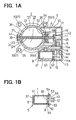
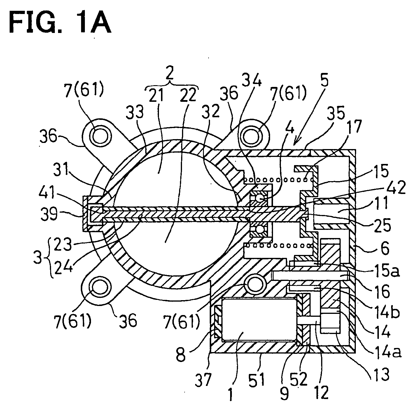
- FIG. 1A is a cross-sectional view showing overall structure of a throttle control apparatus of an engine;
- FIG. 1B is a cross-sectional view showing a motor holder of the throttle body, and a motor (first embodiment);
- FIG. 2 is a cross-sectional view showing an engine joint section of the throttle body (the first embodiment);
- FIG. 3 is a cross-sectional view showing throttle valve and its shaft of a throttle control apparatus of an engine. (the first embodiment);
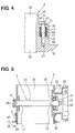
- FIG. 4 is a cross-sectional view showing the engine joint section of the throttle body (second embodiment);
- FIG. 5 is a cross-sectional view showing the engine joint section of the throttle body (the third embodiment); and
- FIG. 6 is a cross-sectional view showing overall structure of a throttle control apparatus of an engine (related art).
-
- In the first embodiment shown in FIG. 1A, a throttle control apparatus of an engine comprises a
motor 1, which structures an actuator; reduction gears (13, 14, 15), which decelerate the rotation speed of themotor 1 by a predetermined reduction ratio; athrottle valve 2, which is driven to rotate by themotor 1 via the reduction gears; athrottle body 5, which rotatably supports a shaft 3 (spindle section, valve shaft) of thethrottle valve 2 via a ball bearing 4 and rigidly accommodates themotor 1; asensor cover 6, which encloses the opening side of thethrottle body 5; and an engine control apparatus (engine control unit: ECU), which controls the rotation speed of the engine by driving of themotor 1 corresponding to the manipulation degree by a driver (the stepping degree of an accelerator pedal) so that the opening of thethrottle valve 2 is controlled to corresponding opening degree. In anintake manifold 10, anair intake passage 70 is formed to connect anair intake passage 30 formed in thethrottle body 5 and a combustion chamber of each cylinder of the engine. - Here, an accelerator position sensor (not shown) is wired with the ECU. The accelerator position sensor converts the stepping degree of the accelerator pedal by the driver into electric signals (accelerator position signals), and transmits the accelerator position signals to the ECU. The throttle control apparatus has a throttle position sensor (not shown) to convert the opening of the
throttle valve 2 into an electric signals (throttle opening signals) and to transmit the throttle opening signals of thethrottle valve 2 to the ECU. - In this embodiment, the ECU is structured to perform feedback control (PID control: proportional integral differential control) for the
motor 1 to eliminate the deviation between the throttle opening signal from the throttle position sensor and the accelerator position signal from the accelerator position sensor. Thesensor cover 6 is made of electrically insulative resin to insulate each external connection terminals of the throttle position sensor and each power supply terminal for themotor 1. Thesensor cover 6 has aconcave sensor holder 11 to rigidly lock the throttle position sensor. - The
motor 1 is a driving source, and has plural permanent magnets, armature core, armature coils and so on in the motor housing. The reduction gears have apinion gear 13 fixed to the outer periphery of thepower spindle 12 of themotor 1; anintermediate reduction gears 14, which rotate as engaging with thepinion gear 13; and a rotation member (rotor core) 15 which rotates as engaging with theintermediate reduction gears 14. Theintermediate reduction gears 14 are integrally molded with metal or resin, and are rotatably fixed on the outer periphery of a supportingshaft 16 which is a rotation center. Theintermediate reduction gears 14 have alarge diameter gear 14a engaging thepinion gear 13 and asmall diameter gear 14b engaging thereduction gear 15a of therotation member 15. One axial end of the supportingshaft 16 is press-inserted into a concavity formed in the inner wall of thethrottle body 5. Here, thepinion gear 13 and theintermediate reduction gears 14 are rotation power transmission means to transmit rotation power of themotor 1 to thereduction gear 15a of therotation member 15. - The
rotation member 15 is formed in a predetermined approximately ring-shape with metal. In the outer periphery of the cylindrical section of therotation member 15, thereduction gear 15a is formed to engage with the small-diameter gear 14b of the intermediate reduction gears 14. In the inner periphery of the cylindrical section of therotation member 15, permanent magnets (not shown) are bonded with glue or the like opposing against the outer periphery of the throttle position sensor. In the center of therotation member 15, a through-hole is formed. The right end section of a reinforcing member 24 (described below) in FIG. 1A penetrates the through-hole. Subsequently, the right end section of the reinforcingmember 24 in FIG. 1A (reduction gear clamp section 25) is crimped so that therotation member 15 is fixed with the right end section of theshaft 3 in FIG. 1A. Between the left end surface of the cylindrical section of therotation member 15 in FIG. 1A and the outer wall surface of the bore wall section 33 (the right end surface in FIG. 1A), a coil-shapedreturn spring 17 is disposed to set thethrottle valve 2 and itsshaft 3 back to the initial position when the engine is in idling rotation speed. - The
throttle valve 2 is a butterfly-type rotary valve to control intake air flow fed into the engine. Thethrottle valve 2 comprises the firstsemicircular plate section 21 extended from the top end surface of theshaft 3 upward in FIG. 1A and the secondsemicircular plate section 22 extended from the bottom end surface of theshaft 3 downward in FIG. 1A. Theshaft 3 has a cylindrical resinous moldedsection 23 integrally molded with heatproof resin and the reinforcing member (metallic center core member) 24 to reinforce the resinous moldedsection 23. - As shown in FIG. 1A, the
throttle body 5, which is integrally molded with heatproof resin, structures a part of an engine air intake pipe connecting with theengine intake manifold 10, and rotatably supports thethrottle valve 2. Thisthrottle body 5 has an annularbore wall section 33. Inside of thebore wall section 33, approximately circularair intake passage 30, in which intake air flows to the engine, is formed. - In the
bore wall section 33 of thethrottle body 5, a firstcylindrical shaft bush 31, and a secondcylindrical shaft bush 32 and acylindrical bearing holder 34 are disposed. The secondcylindrical shaft bush 32 rotatably supports the first supported section and the second supported section of theshaft 3. Thecylindrical bearing holder 34 rotatably supports the second supported section of theshaft 3 via theball bearing 4. Inside of thefirst shaft bush 31 and thesecond shaft bush 32, a first circular shaft through-hole 41 and a second circular shaft through-hole 42 are formed so that theshaft 3 of thethrottle valve 2 passes through. At the left end of thefirst shaft bush 31 in FIG. 1A, aplug 39 is fit to block the opening of thefirst shaft bush 31. - On the sidewall of the
bore wall section 33,containershaped gear case 35 is integrally formed with heatproof resin to rotatably accommodate therotation member 15 including thereduction gear 15a. At the opening side of thegear case 35, asensor cover 6 made of highly electrically insulative resin, is disposed. In the internal space formed between thegear case 35 and thesensor cover 6, the reduction gears are rotatably accommodated - On the outer periphery of the
bore wall section 33, engine joint sections (mounting flange, mount section on the engine, installation section on the engine) 36 are integrally molded with heatproof resin so that the enginejoint sections 36 radially extends. - As shown in FIG. 2, at the engine
joint sections 36, thethrottle body 5 is mounted on ajoint end face 71 of theengine intake manifold 10 with clamping members such asplural clamp bolts 72 andplural washers 73 or the like. As shown in FIG. 1A, the enginejoint sections 36 radially extend outward from outer periphery of thebore wall section 33. - As shown in FIG. 2, on the top end face (bolt flange face) 44 in FIG. 2 of the engine
joint section 36, on inner peripheral surface of the through-hole 45 in which theclamp bolt 72 passes through, and on the bottom end face (mounting flange face) 46 in FIG. 2 corresponding to ajoint end face 71 of theengine intake manifold 10, aflange vibration insulator 7 is integrally formed with resin (two colored molding) to enhance vibration insulation property of thethrottle body 5. - As shown in FIG. 1A, at the sidewall of the
bore wall section 33, and on the lower side of thegear case 35 in FIG. 1A, amotor holder 37 is integrally formed with heatproof resin to lock themotor 1. As shown in FIG. 1B, themotor holder 37 internally has a bottomedcylindrical motor case 51 to accommodate themotor 1, amotor cover 52 to plug the opening side of themotor case 51, and abottom vibration insulator 8 and aceiling vibration insulator 9 to enhance vibration-proof property of themotor 1. - On the
motor case 51, plural detent claws (snap hooks) 53 are formed to accommodate and to support themotor 1 and themotor cover 52. Thedetent claws 53 are hooked on right side end of themotor cover 52 in FIG. 1B by its elastically deformable section as penetrating plural insertion holes 54 formed in themotor cover 52. In the center of themotor cover 52 and theinsulator 9, trough-holes power spindle 12 of themotor 1 penetrates the trough-holes motor cover 52 can be fixed on the opening side of themotor case 51. - The
flange vibration insulators 7, thebottom vibration insulator 8 and theceiling vibration insulator 9 are integrally formable with the heatproof resinous member of thethrottle body 5, and are made of elastically deformable heatproof elastomer. AS the heatproof elastomer, for example, high density nytril butadiene rubber (H-NBR), nytril butadiene rubber (NBR), silicone rubber, ethylene propylene diene monomer (EPDM), acrylate resin, poly urethane resin (PUR), elastomer and so on can be used. - As shown in FIG. 2, the
flange vibration insulator 7 is integrally formed with resin (molded in two colors) on the enginejoint section 36 of thethrottle body 5, and has an approximately ring-shapedbolt seat 61 on which the head section of theclamp bolts 72 contacts; acylindrical section 62 extended from thebolt seat 61 downward in FIG. 2; andannular section 63 extended in the radial direction of thebore wall section 33 from the lower end section of thecylindrical section 62 in FIG. 2 and contacting thejoint face 71 of theengine intake manifold 10, and so on. On theflange vibration insulator 7, a ring-shapedseal section 64 is formed between the enginejoint section 36 and thejoint end face 71 of theintake manifold 10 to avoid leakage of intake air. - In each of the
cylindrical section 62,insertion hole 62a is internally formed so that the shaft of theclamp bolt 72 is inserted into theinsertion hole 62a. - As shown in FIG. 1B, the
bottom vibration insulator 8 is integrally formed with resin (molded in two colors) on the left side end face of themotor case 51 in FIG. 1B (motor mounting face, bottom face). Theceiling vibration insulator 9 is insert-molded on the left side end face of themotor cover 52 in FIG. 1B (motor mounting face, top face). - As shown in FIG. 3, in a cavity formed by a resin molding dies including a sliding die to mold the air intake passage 30 (refer to FIG. 2) and a sliding die, which is for molding the first shaft through-
hole 41 and the second shaft through-hole 42, heat-melt heatproof resin is injected from one or two or more gates, and inside of the cavity of the molding die is formed with heatproof resin. The heatproof resinous member filled in the molding die is taken out, cooled and hardened (solidified), or the heatproof resinous member is cooled and hardened (solidified) in the molding dies. Thus, a resinous molded member is formed including thefirst shaft bush 31; thesecond shaft bush 32; thebore wall section 33; the bearingholder 34; thegear case 35; the enginejoint section 36 and themotor holder 37. - In a cavity formed by the resin molding dies, the cooled and hardened resinous molded member is put. Heated and melt heatproof elastomer is injected from one or two or more gates. Then, in a gap between the resin molding dies and the resinous molded member, the melt heatproof elastomer is injected and filled. The resinous molded member and the heatproof elastomer are taken out of the cavity of the molding dies and cooled, or the resinous member and the heatproof elastomer in the cavity of the molding dies are cooled. Thus, the
bottom vibration insulator 8 is integrated with the resinous molded member to be thethrottle body 5 molded in two colors. As shown in FIG. 1B, theceiling vibration insulator 9 is also molded in two colors to be integrated with themotor cover 52 in the same manner as thebottom vibration insulator 8. (Or, theceiling vibration insulator 9 is bonded to the motor cover 52. ) - The
motor 1 is attached in themotor case 51 of thethrottle body 5. Themotor cover 52 with thebottom vibration insulator 9 is attached so that thepower spindle 12 of themotor 1 penetrates the through-hole motor cover 52 are penetrated by theplural detent claws 53 formed on themotor case 51, themotor cover 52 is attached on the opening side of themotor case 51. - Thus, the left end section of the
motor 1 in FIG. 1B (the rear section of the motor 1) receives elastic force from thebottom vibration insulator 8 added on the bottom face of themotor case 51, the right end section of themotor 1 in FIG. 1A (the front section of the motor 1) receives elastic force from theceiling vibration insulator 9 added on the ceiling face of themotor cover 52. Themotor cover 52 presses themotor 1 via theceiling vibration insulator 9. Themotor cover 52 is pushed back by reactive force of thebottom vibration insulator 8 and theceiling vibration insulator 9, and is held by theplural detent claws 53. Thus, vibration-proof property of themotor 1 locked between themotor holder 37, that is the bottom face of the motor case 51 (the motor mounting face), and the ceiling face of the motor cover 52 (the motor mounting face) can be enhanced. - When a driver steps and presses an accelerator pedal, accelerator position signals from the accelerator position sensor are input to the ECU. By the ECU, the
motor 1 shown in FIG. 1 is energized, and thepower spindle 12 of themotor 1 rotates so that opening of thethrottle valve 2 becomes a designated opening degree. By rotation of thepower spindle 12, thepinion gear 13 rotates. The rotation power is transmitted to thelarge diameter gear 14a of the intermediate reduction gears 14. When thesmall diameter gear 14b rotates around the supportingshaft 16 accompanied by the rotation of thelarge diameter gear 14a, therotation member 15 rotates with itsreduction gear 15a being engaged with thesmall diameter gear 14b. Thus, therotation member 15 rotates with theshaft 3, and theshaft 3 rotates by designated angle so that thethrottle valve 2 is kept in designated angle in theair intake passage 30 formed in thethrottle body 5 toward the engine. - Shown in FIG. 2, the
flange vibration insulator 7 made of heatproof elastomer and the enginejoint section 36 of thethrottle body 5, which is integrally formed with heatproof resin, are screwed with theplural clamp bolts 72 onto thejoint end face 71 of theengine intake manifold 10. By theflange vibration insulator 7 added on the enginejoint section 36 of thethrottle body 5, engine vibration transferred from theengine intake manifold 10 can be absorbed. Thus, vibration of thethrottle body 5 can be suppressed. As a result, vibration-proof property of the entire throttle control apparatus can be improved. - As shown in FIG. 1A, by the
bottom vibration insulator 8 added on the bottom face (motor mounting face) of themotor case 51 of themotor holder 37, and theceiling vibration insulator 9 added on the ceiling face (motor mounting face) of themotor cover 52, themotor 1 is locked between themotor holder 37 and themotor cover 52. Thus, if engine vibration is transferred to themotor holder 37, the engine vibration can be absorbed. Thus, vibration of themotor 1 can be suppressed and themotor 1 does not vibrate largely so that vibration-proof property of themotor 1 can be enhanced. Thus, engagement incomplete between thepinion gear 13 disposed on thepower spindle 12 and thelarge diameter gear 14a of the intermediate reduction gears 14 does not occur. Therefore, via the reduction gears, the rotation power of themotor 1 can be stably transmitted to thethrottle valve 2 and itsshaft 3. Thus, the opening of thethrottle valve 2 is set to aimed angle so that the intake air flow to the engine becomes desired rate. The controllability of the opening of thethrottle valve 2 by the throttle control apparatus can be enhanced so that engine rotation speed corresponding to the degree of stepping the accelerator pedal can be obtained. - The
bottom vibration insulator 8 and theceiling vibration insulator 9 added on themotor holder 37 of thethrottle body 5 need not be independently assembled. Because thebottom vibration insulator 8 is two-color molded on the bottom face (motor mounting face)of themotor case 51, and theceiling vibration insulator 9 is integrally fixed on the ceiling face (motor mounting face) of themotor cover 52. - As shown in FIG. 2, the
flange vibration insulator 7 need not be independently assembled between the mountingflange face 46 of the enginejoint section 36 and thejoint end face 71 of theengine intake manifold 10. - Furthermore, the
flange vibration insulator 7 need not be independently assembled on thebolt flange face 44 and on theinsertion hole 45 of the enginejoint face 36 of thethrottle body 5. - As shown in FIG. 1B, the
motor cover 52 is pushed back by the reactive force of pushing of theceiling vibration insulator 9, and is held by theplural detent claws 53 integrally formed on themotor case 51. Thus, bolts and screws for locking themotor 1 on themotor holder 37 are not necessary. The number of the components is decreased, and assembling workability can be improved. Therefore, cost can be reduced, and productivity can be improved. - By eliminating a mounting flange integrally formed on a motor housing of the
motor 1, production cost of themotor 1 itself can be reduced. Without forming the mounting flange on the motor housing of themotor 1, the rear end section of themotor 1 is elastically pushed by thebottom vibration insulator 8 added on the motor mounting face of themotor case 51, and the front end section of themotor 1 is elastically pushed by theceiling vibration insulator 9 added on themotor cover 52. Thus, themotor 1 can be locked on themotor holder 37. - In the second embodiment shown in FIG. 4, in each engine
joint section 36 of thethrottle body 5, thebolt flange face 44; theinsertion hole 45 in which theclamp bolt 72 passes through; and the mountingflange 46 corresponding to thejoint end face 71 of theengine intake manifold 10 are formed. Theinsertion hole 45 is formed so that its inner diameter of the lower end side (the engine side) is formed larger than that of the upper end side (opposite side of the engine) in FIG. 4. In thelarger insertion hole 47, to enhance vibration-proof property of thethrottle body 5, plural cylindrical vibration insulators 7 (flange vibration insulators) are integrally molded with resin (two colored molding) at plural places. - Each
flange vibration insulator 7 is molded with resin in each metalliccylindrical reinforcing member 65 made of iron or the like in order to avoid buckling deformation or the like of the enginejoint section 36 by the axial force of theclamp bolts 72. That is, each reinforcingmember 65 integrated with theflange vibration insulator 7 is insert-molded in the heatproof resinous member which forms the enginejoint section 36. From the lower end of theflange vibration insulator 7 in FIG. 4, a ring-shapedseal section 64 is formed to protrude toward lower direction in FIG. 4 to avoid leakage of intake air from between thethrottle body 5 and thejoint end face 71 of theintake manifold 10. - In the third embodiment as shown in FIG. 5, the
throttle body 5 made of heatproof resin and enginejoint section 36 made of metallic plate are separately formed. Before mounting thethrottle body 5 on thejoint end face 71 of the engine intake manifold 10 (refer to FIG. 2), thethrottle body 5 and the enginejoint section 36 made of metallic plate are integrated. - The engine
joint section 36 has thebolt flange face 44, theinsertion hole 45 and the mountingflange face 46. The enginejoint section 36 is bonded with an approximately cylindricalflange vibration insulator 7 to enhance vibration-proof property of thethrottle body 5. From the lower side end of theflange vibration insulator 7 in FIG. 5, a ring-shapedseal section 64 is formed to protrude downward in FIG. 5 to avoid leakage of intake air from between thethrottle body 5 and thejoint end face 71 of theintake manifold 10. - In this embodiment, the
shaft 3 of thethrottle valve 2 is rotatably supported by the bearingholder 34 of thethrottle body 5 viaball bearings 4. On the right side end face of the reinforcingmember 24 in FIG. 5, a reductiongear clamp section 25 is disposed to lock therotation member 15 by crimping. - The degree of stepping of the accelerator pedal can be mechanically transmitted to the
throttle valve 2 and itsshaft 3 via a wire cable and an acceleration lever so that thethrottle valve 2 and itsshaft 3 are actuated. - Referring to FIG. 1, the
bottom vibration insulator 8 added on the motor mounting face of themotor holder 37 of thethrottle body 5 or theceiling vibration insulator 9 can be integrally formed with resin or integrated with the motor mounting face of themotor case 51 or the motor mounting face of themotor cover 52. - As shown in FIG. 2, The
flange vibration insulator 7 can be integrally formed with resin with the enginejoint section 36 to be disposed just between the mountingflange face 46 of the enginejoint section 36 of thethrottle body 5 andjoint end face 71 of theengine intake manifold 10. The resinous member, which structures thethrottle body 5, and theflange vibration insulators 7 and thebottom vibration insulator 8 can be molded simultaneously. - The
throttle body 5 can be integrally formed with metal or can be formed by aluminum die-casting. - The
throttle valve 2 and itsshaft 3 can be integrally formed with such metal that iron or the like. - The
throttle valve 2 and theshaft 3 can be formed separately and thethrottle valve 2 can be screwed on theshaft 3 using threads such as mounting bolts or clamp screws. By resinous molding of the rotatingmember 15, which has thereduction gears 15a, the rotatingmember 15 can be integrally molded with resin on the resinous moldedsection 23 of theshaft 3 of thethrottle valve 2. - The
flange vibration insulator 7, thebottom vibration insulator 8 and theceiling vibration insulator 9 can be formed separately from thethrottle body 5, and can be supported by external force. - Various modifications and alternation may be made to the above embodiments without departing from the spirit of the present invention.
- Vibration insulators (7), (8), (9) made of heatproof elastomer are integrally molded with an engine joint section (36) of the heatproof resinous throttle body (5) and a motor holder (37). Thus, engine vibration transferred from an engine intake manifold to the throttle body (5) and the motor (1) can be absorbed by the vibration insulators (7), (8), (9). Therefore, without increase of components and reduction of assembling workability, the vibration can be suppressed.
Claims (8)
- A throttle control apparatus comprising:characterized in that,a throttle valve (2) having a shaft (3) and for controlling air intake flow fed into an engine;a throttle body (5) rotatably supporting the shaft (3) of the throttle valve (2); anda vibration insulator (7, 61, 62, 63, 64) for suppressing vibration transferred from the engine to the throttle body (5),
the insulator (7, 61, 62, 63, 64) is integrally formed with the throttle body (5). - A throttle control apparatus according to claim 1 further comprising:characterized in that,a joint section (36) integrally formed with the throttle body (5) to combine with an intake manifold of the engine (10),
the insulator (7, 61, 62, 63, 64) is disposed near the joint section (36). - A throttle control apparatus according to claim 1 or 2,
characterized in that,
the insulator (7, 61, 62, 63, 64) has an air-tight section to tightly seal between a sidewall section of the engine and a mounting flange (46) of the throttle body (5). - A throttle control apparatus comprising:characterized in that,a motor (1) for generating rotation power;a throttle valve (2) having a shaft (3) driven by the rotation power of the motor (1) for controlling air intake flow fed to the engine;a throttle body (5) rotatably supporting the shaft (3) of the throttle valve (2) and accommodating the motor (1); anda vibration insulator (8, 9) for suppressing vibration transferred from the engine to the motor (1),
the vibration insulator (8, 9) is integrated with the throttle body (5). - A throttle control apparatus according to claim 4, further comprising:characterized in that,a motor holder (37) positioned to lock the motor (1) and integrated with the throttle body (5),
the insulator (8, 9) is disposed near the motor holder (37). - A throttle control apparatus according to claim 5, further comprising:characterized in that,a motor case (51) included in the motor holder (37) and accommodates the motor (1);a motor cover (52) included in the motor holder (37) and supports the motor (1); andan elastically deformable snap hook (53) included in one of the motor case (51) and the motor cover (52),
the motor (1) is supported by elastic force of the vibration insulator (8, 9) and the snap hook (53). - A throttle control apparatus according to claim 5,
characterized in that,
the motor (1) is remotely supported by the throttle body (5). - A throttle control apparatus according to any one of claims 1 to 7, characterized in that,the throttle body (5) is formed with heatproof resin or aluminum die-cast, andthe vibration insulator (7, 8, 9, 61, 62, 63, 64) is made of elastically deformable heatproof resin.
Applications Claiming Priority (2)
| Application Number | Priority Date | Filing Date | Title |
|---|---|---|---|
| JP2002250099A JP2004084636A (en) | 2002-08-29 | 2002-08-29 | Throttle control device |
| JP2002250099 | 2002-08-29 |
Publications (2)
| Publication Number | Publication Date |
|---|---|
| EP1394392A1 true EP1394392A1 (en) | 2004-03-03 |
| EP1394392B1 EP1394392B1 (en) | 2006-02-01 |
Family
ID=31492594
Family Applications (1)
| Application Number | Title | Priority Date | Filing Date |
|---|---|---|---|
| EP03019495A Expired - Lifetime EP1394392B1 (en) | 2002-08-29 | 2003-08-28 | Throttle control apparatus with vibration insulator |
Country Status (5)
| Country | Link |
|---|---|
| US (1) | US6973917B2 (en) |
| EP (1) | EP1394392B1 (en) |
| JP (1) | JP2004084636A (en) |
| CN (1) | CN1487183A (en) |
| DE (1) | DE60303412T2 (en) |
Families Citing this family (17)
| Publication number | Priority date | Publication date | Assignee | Title |
|---|---|---|---|---|
| JP3364873B2 (en) * | 1997-03-13 | 2003-01-08 | 株式会社日立ユニシアオートモティブ | Electronically controlled throttle valve device for internal combustion engine |
| JP4012893B2 (en) * | 2004-06-11 | 2007-11-21 | トヨタ自動車株式会社 | Control device for internal combustion engine |
| JP2006017080A (en) * | 2004-07-05 | 2006-01-19 | Denso Corp | Intake control device for internal combustion engine |
| DE102004043125B4 (en) * | 2004-09-07 | 2017-10-05 | Robert Bosch Gmbh | throttling device |
| US7503310B2 (en) * | 2005-03-21 | 2009-03-17 | Continental Automotive Canada, Inc. | Packaging arrangement for an increment position sensor |
| JP2007092667A (en) * | 2005-09-29 | 2007-04-12 | Aisan Ind Co Ltd | Molded article and throttle device provided with molded article |
| JP4551351B2 (en) * | 2006-04-18 | 2010-09-29 | 株式会社デンソー | Throttle valve device |
| EP1967719B1 (en) * | 2007-03-09 | 2009-05-13 | Magneti Marelli S.p.A. | Valve for adjusting the air flow rate in an internal combustion engine |
| JP5325068B2 (en) * | 2009-10-08 | 2013-10-23 | 三菱重工業株式会社 | Engine intake system |
| JP5249261B2 (en) * | 2010-02-18 | 2013-07-31 | 株式会社デンソー | Throttle valve device |
| CN102235248B (en) * | 2010-04-23 | 2014-03-19 | 上海奥众汽车部件制造有限公司 | Axial positioning control mechanism for electric spray throttle valve body of automobile |
| CN102255420A (en) * | 2010-05-21 | 2011-11-23 | 上海奥众汽车部件制造有限公司 | Direct-current motor pressure plate assembly structure for electronic throttle valve body |
| DE102012111948B4 (en) | 2012-12-07 | 2015-05-28 | Pierburg Gmbh | Valve device for an internal combustion engine |
| EP3346114B1 (en) * | 2015-09-02 | 2020-11-04 | Hitachi Automotive Systems, Ltd. | Throttle valve control device |
| JP7083746B2 (en) * | 2018-12-26 | 2022-06-13 | 愛三工業株式会社 | Intake device |
| JP7556019B2 (en) * | 2020-03-11 | 2024-09-25 | 株式会社コガネイ | Manifold solenoid valves and valve bases |
| KR20240084899A (en) * | 2022-12-07 | 2024-06-14 | 주식회사 현대케피코 | Assembly method and structure for improvement interval between shaft of electronic type throttle actuator |
Citations (4)
| Publication number | Priority date | Publication date | Assignee | Title |
|---|---|---|---|---|
| DE4035871A1 (en) * | 1990-11-12 | 1992-05-14 | Vdo Schindling | Vibration insulation and uncoupling flange - is for connection of throttle valve union to load adjusting device |
| JPH08232787A (en) * | 1995-02-27 | 1996-09-10 | Toyota Motor Corp | Support device for intake system for internal combustion engine |
| DE19912231A1 (en) * | 1998-04-07 | 1999-10-14 | Aisan Ind | Throttle flap and valve control device in engines |
| US5979405A (en) * | 1997-03-13 | 1999-11-09 | Unisia Jecs Corporation | Apparatus for controlling a throttle valve electronically in an internal combustion engine |
Family Cites Families (9)
| Publication number | Priority date | Publication date | Assignee | Title |
|---|---|---|---|---|
| JPH0561448A (en) | 1991-09-04 | 1993-03-12 | Canon Inc | Display device for computer system |
| JPH10131772A (en) | 1996-10-31 | 1998-05-19 | Aisin Seiki Co Ltd | Throttle control device |
| JPH10131773A (en) | 1996-10-31 | 1998-05-19 | Aisin Seiki Co Ltd | Throttle control device |
| JP3361031B2 (en) * | 1997-03-19 | 2003-01-07 | 株式会社日立ユニシアオートモティブ | Electronically controlled throttle valve device for internal combustion engine |
| JP3516581B2 (en) | 1997-12-23 | 2004-04-05 | 株式会社日立ユニシアオートモティブ | Throttle valve device |
| JP3696732B2 (en) * | 1998-06-19 | 2005-09-21 | 株式会社日立製作所 | Electric throttle valve device |
| JP2000130259A (en) | 1998-10-20 | 2000-05-09 | Uchiyama Mfg Corp | Seal structure of intake manifold |
| JP2000145482A (en) * | 1998-11-11 | 2000-05-26 | Asmo Co Ltd | Throttle control device |
| JP2002339766A (en) * | 2001-05-15 | 2002-11-27 | Aisan Ind Co Ltd | Throttle valve control device |
-
2002
- 2002-08-29 JP JP2002250099A patent/JP2004084636A/en active Pending
-
2003
- 2003-08-26 US US10/647,220 patent/US6973917B2/en not_active Expired - Fee Related
- 2003-08-28 EP EP03019495A patent/EP1394392B1/en not_active Expired - Lifetime
- 2003-08-28 DE DE60303412T patent/DE60303412T2/en not_active Expired - Fee Related
- 2003-08-28 CN CNA031555543A patent/CN1487183A/en active Pending
Patent Citations (4)
| Publication number | Priority date | Publication date | Assignee | Title |
|---|---|---|---|---|
| DE4035871A1 (en) * | 1990-11-12 | 1992-05-14 | Vdo Schindling | Vibration insulation and uncoupling flange - is for connection of throttle valve union to load adjusting device |
| JPH08232787A (en) * | 1995-02-27 | 1996-09-10 | Toyota Motor Corp | Support device for intake system for internal combustion engine |
| US5979405A (en) * | 1997-03-13 | 1999-11-09 | Unisia Jecs Corporation | Apparatus for controlling a throttle valve electronically in an internal combustion engine |
| DE19912231A1 (en) * | 1998-04-07 | 1999-10-14 | Aisan Ind | Throttle flap and valve control device in engines |
Non-Patent Citations (1)
| Title |
|---|
| PATENT ABSTRACTS OF JAPAN vol. 1997, no. 01 31 January 1997 (1997-01-31) * |
Also Published As
| Publication number | Publication date |
|---|---|
| US6973917B2 (en) | 2005-12-13 |
| JP2004084636A (en) | 2004-03-18 |
| EP1394392B1 (en) | 2006-02-01 |
| CN1487183A (en) | 2004-04-07 |
| DE60303412D1 (en) | 2006-04-13 |
| US20040040538A1 (en) | 2004-03-04 |
| DE60303412T2 (en) | 2006-09-07 |
Similar Documents
| Publication | Publication Date | Title |
|---|---|---|
| US6973917B2 (en) | Throttle control apparatus | |
| EP1191210B1 (en) | Throttle device of internal combustion engine | |
| US6626143B1 (en) | Throttle device of internal combustion engine | |
| US6591809B2 (en) | Throttle device for internal-combustion engine | |
| US7063067B2 (en) | Intake air control apparatus for internal combustion engine | |
| KR100790670B1 (en) | Supporting device for actuator received in housing | |
| JP4093173B2 (en) | Throttle control device for internal combustion engine | |
| US7219652B2 (en) | Bearing support device | |
| JPH10306735A (en) | Engine throttle device | |
| US20040119041A1 (en) | Throttle bodies with throttle valves actuated by motors | |
| US20020033166A1 (en) | Electronically controlled throttle apparatus for an engine | |
| US11563358B2 (en) | Rotary actuator having resin molded body and connection terminals | |
| EP1612387A2 (en) | Throttle device for internal combustion engine | |
| US11699936B2 (en) | Rotary actuator having board fixing member meshing with case fastening member | |
| JPH1047520A (en) | Throttle body | |
| JP2004132235A (en) | Throttle control device | |
| CN116547889A (en) | Electric motor for an actuating device of a motor vehicle and method for mounting a camshaft adjuster | |
| JP2004092617A (en) | Manufacturing method of throttle control device | |
| JP3820619B2 (en) | Fuel distribution pipe | |
| KR20240157834A (en) | Actuator for shift-by-wire system and manufacturing method of housing of the same |
Legal Events
| Date | Code | Title | Description |
|---|---|---|---|
| PUAI | Public reference made under article 153(3) epc to a published international application that has entered the european phase |
Free format text: ORIGINAL CODE: 0009012 |
|
| AK | Designated contracting states |
Kind code of ref document: A1 Designated state(s): AT BE BG CH CY CZ DE DK EE ES FI FR GB GR HU IE IT LI LU MC NL PT RO SE SI SK TR |
|
| AX | Request for extension of the european patent |
Extension state: AL LT LV MK |
|
| 17P | Request for examination filed |
Effective date: 20040322 |
|
| 17Q | First examination report despatched |
Effective date: 20040430 |
|
| AKX | Designation fees paid |
Designated state(s): DE FR GB |
|
| GRAP | Despatch of communication of intention to grant a patent |
Free format text: ORIGINAL CODE: EPIDOSNIGR1 |
|
| GRAS | Grant fee paid |
Free format text: ORIGINAL CODE: EPIDOSNIGR3 |
|
| GRAA | (expected) grant |
Free format text: ORIGINAL CODE: 0009210 |
|
| AK | Designated contracting states |
Kind code of ref document: B1 Designated state(s): DE FR GB |
|
| REG | Reference to a national code |
Ref country code: GB Ref legal event code: FG4D |
|
| REF | Corresponds to: |
Ref document number: 60303412 Country of ref document: DE Date of ref document: 20060413 Kind code of ref document: P |
|
| ET | Fr: translation filed | ||
| PLBE | No opposition filed within time limit |
Free format text: ORIGINAL CODE: 0009261 |
|
| STAA | Information on the status of an ep patent application or granted ep patent |
Free format text: STATUS: NO OPPOSITION FILED WITHIN TIME LIMIT |
|
| 26N | No opposition filed |
Effective date: 20061103 |
|
| PGFP | Annual fee paid to national office [announced via postgrant information from national office to epo] |
Ref country code: DE Payment date: 20070823 Year of fee payment: 5 |
|
| PGFP | Annual fee paid to national office [announced via postgrant information from national office to epo] |
Ref country code: GB Payment date: 20070822 Year of fee payment: 5 |
|
| PGFP | Annual fee paid to national office [announced via postgrant information from national office to epo] |
Ref country code: FR Payment date: 20070808 Year of fee payment: 5 |
|
| GBPC | Gb: european patent ceased through non-payment of renewal fee |
Effective date: 20080828 |
|
| REG | Reference to a national code |
Ref country code: FR Ref legal event code: ST Effective date: 20090430 |
|
| PG25 | Lapsed in a contracting state [announced via postgrant information from national office to epo] |
Ref country code: DE Free format text: LAPSE BECAUSE OF NON-PAYMENT OF DUE FEES Effective date: 20090303 Ref country code: FR Free format text: LAPSE BECAUSE OF NON-PAYMENT OF DUE FEES Effective date: 20080901 |
|
| PG25 | Lapsed in a contracting state [announced via postgrant information from national office to epo] |
Ref country code: GB Free format text: LAPSE BECAUSE OF NON-PAYMENT OF DUE FEES Effective date: 20080828 |