EP1394362A2 - Floating brush seal assembly - Google Patents
Floating brush seal assembly Download PDFInfo
- Publication number
- EP1394362A2 EP1394362A2 EP03255328A EP03255328A EP1394362A2 EP 1394362 A2 EP1394362 A2 EP 1394362A2 EP 03255328 A EP03255328 A EP 03255328A EP 03255328 A EP03255328 A EP 03255328A EP 1394362 A2 EP1394362 A2 EP 1394362A2
- Authority
- EP
- European Patent Office
- Prior art keywords
- brush seal
- component
- seal assembly
- gap
- axial
- Prior art date
- Legal status (The legal status is an assumption and is not a legal conclusion. Google has not performed a legal analysis and makes no representation as to the accuracy of the status listed.)
- Granted
Links
- 238000007789 sealing Methods 0.000 claims abstract description 7
- 238000000034 method Methods 0.000 claims description 8
- 239000012530 fluid Substances 0.000 description 6
- 230000000712 assembly Effects 0.000 description 5
- 238000000429 assembly Methods 0.000 description 5
- 238000003466 welding Methods 0.000 description 4
- 239000002783 friction material Substances 0.000 description 2
- 238000007792 addition Methods 0.000 description 1
- WYTGDNHDOZPMIW-RCBQFDQVSA-N alstonine Natural products C1=CC2=C3C=CC=CC3=NC2=C2N1C[C@H]1[C@H](C)OC=C(C(=O)OC)[C@H]1C2 WYTGDNHDOZPMIW-RCBQFDQVSA-N 0.000 description 1
- 238000013459 approach Methods 0.000 description 1
- 239000011248 coating agent Substances 0.000 description 1
- 238000000576 coating method Methods 0.000 description 1
- 238000004891 communication Methods 0.000 description 1
- 238000007796 conventional method Methods 0.000 description 1
- 238000012986 modification Methods 0.000 description 1
- 230000004048 modification Effects 0.000 description 1
- 230000001052 transient effect Effects 0.000 description 1
Images
Classifications
-
- F—MECHANICAL ENGINEERING; LIGHTING; HEATING; WEAPONS; BLASTING
- F16—ENGINEERING ELEMENTS AND UNITS; GENERAL MEASURES FOR PRODUCING AND MAINTAINING EFFECTIVE FUNCTIONING OF MACHINES OR INSTALLATIONS; THERMAL INSULATION IN GENERAL
- F16J—PISTONS; CYLINDERS; SEALINGS
- F16J15/00—Sealings
- F16J15/16—Sealings between relatively-moving surfaces
- F16J15/32—Sealings between relatively-moving surfaces with elastic sealings, e.g. O-rings
- F16J15/3284—Sealings between relatively-moving surfaces with elastic sealings, e.g. O-rings characterised by their structure; Selection of materials
- F16J15/3288—Filamentary structures, e.g. brush seals
-
- F—MECHANICAL ENGINEERING; LIGHTING; HEATING; WEAPONS; BLASTING
- F01—MACHINES OR ENGINES IN GENERAL; ENGINE PLANTS IN GENERAL; STEAM ENGINES
- F01D—NON-POSITIVE DISPLACEMENT MACHINES OR ENGINES, e.g. STEAM TURBINES
- F01D11/00—Preventing or minimising internal leakage of working-fluid, e.g. between stages
- F01D11/005—Sealing means between non relatively rotating elements
-
- F—MECHANICAL ENGINEERING; LIGHTING; HEATING; WEAPONS; BLASTING
- F05—INDEXING SCHEMES RELATING TO ENGINES OR PUMPS IN VARIOUS SUBCLASSES OF CLASSES F01-F04
- F05D—INDEXING SCHEME FOR ASPECTS RELATING TO NON-POSITIVE-DISPLACEMENT MACHINES OR ENGINES, GAS-TURBINES OR JET-PROPULSION PLANTS
- F05D2240/00—Components
- F05D2240/55—Seals
- F05D2240/56—Brush seals
Definitions
- This invention relates to floating brush seal assemblies. Specifically, this invention relates to axial brush seal assemblies that can float in the axial direction within a gap between two components.
- a labyrinth seal comprises a plurality of teeth extending from a disk on one of the components and a honeycomb pad on the other component. The teeth and the pad cooperate to form a serpentine leakage path between the components. The serpentine path inhibits fluid flow between the components.
- labyrinth seals have several drawbacks.
- a brush seal assembly for sealing a gap between a first component and a second component.
- the assembly comprises: a body; bristles extending from the body; and an extension from the body, the extension having an elongated slot therein. The slot, when the brush seal assembly mounts between the first and second components, allows the brush seal assembly to float within the gap.
- an axial brush seal assembly for sealing a gap between a first component and a second component.
- the brush seal assembly comprises: a body; bristles extending from said body; and means for allowing movement of the brush seal assembly in an axial direction within the gap.
- an apparatus comprising: a first component; a second component spaced from the first component in an axial direction; and an axial brush seal assembly movably mounted between the first and second components.
- the brush seal assembly can move in the axial direction.
- a method of sealing a gap between a first component and a second component comprises the steps of: placing an axial brush seal assembly between the first and second components; and allowing the brush seal assembly to float in the gap.
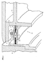
- Figure 1 displays one alternative embodiment of the present invention.
- the figure provides a brush seal assembly 10 that inhibits fluid flow through a gap 11 between a first component 13 and a second component 15 of an apparatus such as a gas turbine engine.
- the components 13, 15 could be stationary or rotating components.
- the figure shows the first component 13 as a rotating component (such as a turbine disc).
- the component 13 could include a ring 17 that acts as a land surface for the brush seal assembly 10.
- the figures also show the second component 15 as a stationary component (such as a turbine nozzle). Since the component 15 remains stationary, no need exists for a ring to provide a land surface like the rotating first component 13 may require. As seen in the figures, multiple elements could form the stationary component 15. Alternatively, both components could be stationary components such as adjacent sections of the engine case, compressor stators and the engine case, or turbine nozzles and the engine case.
- the components 13, 15 exhibit high axial growth transients. In other words, the components 13, 15 move substantially in the axial direction during operation.
- preferred embodiments of the present invention can also accommodate radial growth transients.
- the brush seal assembly 10 serves to inhibit flow through the gap 11 between the components 13, 15 despite the growth transients.
- the depicted embodiment of the present invention allows movement of the brush seal assembly 10 to ensure an adequate seal despite substantial growth transients.
- a substantial growth transient could reduce or increase the gap 11 by up to approximately 15% in the axial direction.
- the brush seal assembly 10 is preferably an axial brush seal assembly.
- the brush seal assembly 10 could use a separate brush seal for each component 13, 15 as seen in Figures 1 and 2.
- the brush seal assembly 10 could be a single brush seal that engages both components 13, 15 such as that shown in Figure 3.
- the brush seal preferably has a conventional arrangement, with a bristle pack 19 secured to a backing plate 21 and a side plate 23 such as by welding the metallic pieces together.
- the annular extension 25 bridges between the backing plates 21.
- the annular extension 25 has a suitable number of circumferentially located slots 27 therein.
- the slots 27 are elongated in the axial direction of the engine.
- the slots are not elongated in the circumferential direction to prevent rotation of the brush seal.
- the slots 27 could receive bushings 29 made from, for example, a suitable low friction material.
- the second component 15 includes threaded blind holes that correspond to the slots 27 in the extension 25.
- suitable fasteners such as set screws 31, extend through the slots 27 in the extension 25 and into the blind holes of the second component 15.
- the head of the screw 31 is preferably larger than the slot 27.
- a spring 33 could surround the shaft of each of the screws 31. The springs 33 help center the brush seal assembly 10 within the engine.
- the second component 15 can move relative to the first component 13 without affecting the performance of the brush seal assembly 10.
- the elongation of the slots 27 in the extension 25 allows movement of the screws 31 from the second component 15 therein.
- the second component 15 should also be able to move relative to the first component 13 during radial growth transients without affecting the performance of the brush seal assembly 10.
- the gap between the extension 25 and the second component 15 allows for such movement.
- the slots 27 allow the screws 31 to move therein. In essence, the present invention allows the brush seal assembly 10 to float between the components 13, 15.
- the brush seal assembly self centers within the gap 11. As transients increase, the bristles of the brush seal assembly 10 comply and increase their lay angle. Similarly, as transients decrease, the bristles of the brush seal assembly 10 relax and decrease their lay angle. Throughout this range of bristle movement, the brush seal assembly 10 maintains a relatively constant leakage flow rate through the gap 11 between the components 13, 15.
- the brush seal assembly 10 could include an annular ring 35 that bridges between the side plates 23.
- the ring 35 could secure to the side plates 23 using any suitable technique such as press-fitting or welding (obviously after the screws 31 have been properly secured in the blind holes).
- the ring 35 prevents fluid flow through the slots 27.
- Other alternative techniques could be used.
- a large washer (not shown) could be placed between the inner diameter of the extension 25 and the head of the screw 31. The washer is sized to occlude the enlarged slots 27 at any position of the screw 31 within the slot 27.
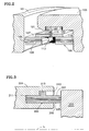
- Figure 2 displays another alternative embodiment of the present invention.
- the figure displays a brush seal assembly 100 that inhibits fluid flow through a gap between a first component 101 and a second component 103 of an apparatus such as a gas turbine engine.
- the first component 101 is preferably a rotating component and the second component 103 is preferably a stationary component.
- the brush seal assembly 100 includes a bristle pack 105 sandwiched between backing plates 107 and side plates 109. Similar to the aforementioned brush seal assembly 10, the brush seal assembly 100 includes an extension 111 that bridges between the backing plates 107.
- the annular extension 111 has a suitable number of threaded holes therein.
- the holes receive a suitable fastener such as a plunger assembly 113.
- the plunger assembly 113 includes a set screw 115 with a plunger 117 extending from the distal end.
- a spring (not shown) within the screw 115 biases the plunger away from the head of the screw 115.
- the spring within the screw 115 also helps center the brush seal asembly 100 within the engine.
- the operator urges the brush seal assembly 100 towards a shoulder 119 of the second component 103.
- the plunger 117 will eventually abut a chamfer 121 on the second component 103.
- the chamfer 121 to depress the plunger 117.
- the brush seal assembly 100 arrives adjacent the shoulder 119.
- the plunger 117 will encounter one of a plurality of elongated slots 123 in the second component 103.
- the spring biases the plunger 117 into the elongated slot 123.
- the brush seal assembly 100 is now fully secured to the second component 103.
- the plunger assemblies 113 could be unscrewed from the extension 111.
- the brush seal assembly 100 may be removed from the second component 103 by disengaging the plunger 117 from the slot 123.
- Conventional techniques to disengage the plunger 117 include providing the proximal end (the end opposite plunger 117) of the plunger assembly 113 with pull levers, knobs or rings (none shown). The operator can actuate these pull levers, knobs or rings to withdraw the plunger 117 from the slot 123.
- the second component 103 can move relative to the first component 101 without affecting the performance of the brush seal assembly 100.
- the elongation of the slots 123 in the second component 103 allows movement of the plunger assemblies 113 therein.
- the plunger assemblies 113 completely occlude the holes in the extension 111. As a result, no leakage paths exist in the extension 111. Therefore, the brush seal assembly 100 does not require the annular ring 35 used by the aforementioned brush seal assembly 10.
- Figure 3 displays another alternative embodiment of the present invention.
- the figure displays a brush seal assembly 200 that inhibits fluid flow througha gap between a first component 201 and a second component 203 of an apparatus such as a gas turbine engine.
- both components 201, 203 are preferably stationary components.
- the brush seal assembly 200 is preferably a single axial brush seal. However, the brush seal assembly 200 could use separate brush seals for each component 201, 203 as seen in Figures 1 and 2.
- the brush seal assembly 200 includes a bristle pack 205 secured to a backing plate 207 and a side plate 209 (with an integral windage cover) such as by welding the metallic pieces together.
- the brush seal assembly 200 can reside within an annular slot 211 in the first component 201.
- the slot 211 is sized to allow the brush seal assembly 200 to move axially ( i.e. parallel to centerline L of the engine) within the engine to accommodate axial growth transients.
- the slot 211 is sized to generally limit radial movement of the brush seal assembly 200 in the engine.
- the slot 211 could have a plurality of circumferentially spaced keyways 213 in communication therewith.
- the keyways 213 accept splines 215 radially extending from the backing plate 207. This arrangement prevents the brush seal assembly 200 from rotating.
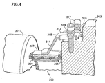
- Figure 4 displays another alternative embodiment of the present invention.
- the figure shows a brush seal assembly 300 that inhibits fluid flow through a gap between a first component 301 and a second component 303 of an apparatus such as a gas turbine engine.
- the first component 301 is preferably a rotating component and the second component 303 is preferably a stationary component
- the brush seal assembly 300 is preferably a single axial brush seal.
- the brush seal assembly 300 could, however, use separate brush seals for each component 301, 303.
- the brush seal assembly 300 includes a bristle pack 305 secured to a backing plate 307 and a side plate 309 (with an integral windage cover) such as by welding the metallic pieces together.
- the annular extension 311 projects from the backing plate 307.
- the annular extension 311 has a plurality of elongated slots 313 therein.
- the slots 313 extend in the axial direction of the engine.
- the slots 311 are not elongated in the circumferential direction to prevent rotation of the brush seal.
- a boss 315 surrounds each slot 313.
- the boss 315/slot 313 could have a low-friction coating thereon, or a bushing (not shown) made from a low friction material could be placed in the slot 313.
- Suitable fasteners such as set screws 317, extend through the slots 313 to mount the brush seal assembly 300 to the second component 303.
- a coil spring 319 surrounds the fastener 317. The spring 319 serves to bias the extension 311 away from the head of the fastener 317 and towards the second component 303.
- the fastener 317 sufficiently compresses the spring 319 to urge the extension 311 against the second component 303.
- the spring 319 should also permit movement of the second component 303 relative to the brush seal assembly 300 by allowing the fastener 317 to move within the elongated slot 313.
- the spring rates of the bristles of the bristle pack 305 keep the brush seal assembly 300 centered within the gap between the components 301, 303. This centering capability also allows the fasteners 317 will move within the slots 313.
- This arrangement allows movement of the second component 303 relative to the first component 301 without affecting the performance of the brush seal assembly 300.
- the elongation of the slots 313 in the extension 311 allows movement of the fasteners 317 therein.
- the present invention allows the brush seal assembly 300 to float between the components 301, 303 in the axial direction.
Landscapes
- Engineering & Computer Science (AREA)
- General Engineering & Computer Science (AREA)
- Mechanical Engineering (AREA)
- Turbine Rotor Nozzle Sealing (AREA)
- Sealing Devices (AREA)
Abstract
Description
Claims (19)
- A brush seal assembly (10;300) for sealing a gap (11)between a first component (13;301) and a second component (15;303), comprising:wherein said slot (27;313), when said brush seal assembly (10;300) mounts between said first (13;301) and second (15;303) component, allows said brush seal assembly to float within said gap (11).a body (21;307);bristles (19;305) extending from said body (21;307) andan extension (25;311) from said body, said extension (25;311) having an elongated slot (27;313) therein;
- The brush seal (10;300) of claim 1, wherein said brush seal assembly can axially float within said gap.
- The brush seal (10;300) of claim 1 or 2, wherein said brush seal is an axial brush seal.
- The brush seal (10;300) of claim 1, 2 or 3, further comprising a spring(33;319) for biasing said brush seal.
- The brush seal (300) of claim 4, wherein said spring (319) biases said brush seal against said second component (303).
- The brush seal (10) of claim 4, wherein said spring (33) biases said brush seal away from said second component (15).
- An axial brush seal assembly (10;100;200;300) for sealing a gap(11) between a first component (13;101;201;301) and a second component (15;103;203;303) comprising:a body (21;107;207;307);bristles (19;105;205;305) extending from said body; andmeans for allowing movement of said brush seal assembly in an axial direction within said gap (27,31;11,123;215,213;313,317).
- The axial brush seal assembly (10;300) of claim 7, wherein said allowing means (27,31;313,317) comprises an extension(25;311) from said body, said extension having slot (27;313) therein elongated in said axial direction.
- The axial brush seal assembly (10;100;200;300)of claim 7, wherein said allowing means (27,31;117,123;213,215;313,317) comprises an elongated slot (27;123;213;313)
- The axial brush seal assembly (100;200) of claim 9, in combination with said second component (103;203), said second component including said elongated slot (123;213) and said brush seal assembly including a member (117;215) extending into said slot.
- The axial brush seal assembly (100;200) of claim 9, in combination with said second component (103;203), said second component including said elongated slot (123;213) and said brush seal assembly resides in said elongated slot.
- An apparatus, comprising:wherein said brush seal assembly can move in said axial direction.a first component (13;101;201;301);a second component (15;103;203;303) spaced from said first component in an axial direction; andan axial brush seal assembly (10;100;200;300)movably mounted between said first and second component;
- The apparatus of claim 12, wherein said brush seal assembly (10;100;200;3 00) includes bristles engaging said first (13;101;201;301) and second (15;103;203;303) components.
- The apparatus of claim 12 or 13, further comprising a spring (33;115;319) to bias said brush seal (10;100;200;300).
- The apparatus of claim 12, 13 or 14, wherein said apparatus is a gas turbine engine.
- A method of sealing a gap (11) between a first component (13;101;201;301) and a second component (15;103;203;303), comprising the steps of:placing an axial brush seal assembly (10;100;200;300) between said first and second components; andallowing said brush seal assembly to float in said gap.
- The method of claim 16, wherein said allowing step comprises allowing said brush seal to float axially in said gap.
- The method of claim 16 or 17, wherein said allowing step includes a step of applying a bias force to said brush seal (10;100;200;300).
- The method of claim 18, wherein said applying step comprises applying a spring bias force to said brush seal (10;100;200;300)
Priority Applications (1)
| Application Number | Priority Date | Filing Date | Title |
|---|---|---|---|
| EP10012672A EP2320031B1 (en) | 2002-08-27 | 2003-08-27 | Engine with a floating brush seal assembly |
Applications Claiming Priority (2)
| Application Number | Priority Date | Filing Date | Title |
|---|---|---|---|
| US64889 | 2002-08-27 | ||
| US10/064,889 US7093835B2 (en) | 2002-08-27 | 2002-08-27 | Floating brush seal assembly |
Related Child Applications (1)
| Application Number | Title | Priority Date | Filing Date |
|---|---|---|---|
| EP10012672.1 Division-Into | 2010-10-01 |
Publications (3)
| Publication Number | Publication Date |
|---|---|
| EP1394362A2 true EP1394362A2 (en) | 2004-03-03 |
| EP1394362A3 EP1394362A3 (en) | 2006-02-08 |
| EP1394362B1 EP1394362B1 (en) | 2011-01-12 |
Family
ID=31493956
Family Applications (2)
| Application Number | Title | Priority Date | Filing Date |
|---|---|---|---|
| EP03255328A Expired - Lifetime EP1394362B1 (en) | 2002-08-27 | 2003-08-27 | Gas turbine engine with a floating brush seal assembly |
| EP10012672A Expired - Lifetime EP2320031B1 (en) | 2002-08-27 | 2003-08-27 | Engine with a floating brush seal assembly |
Family Applications After (1)
| Application Number | Title | Priority Date | Filing Date |
|---|---|---|---|
| EP10012672A Expired - Lifetime EP2320031B1 (en) | 2002-08-27 | 2003-08-27 | Engine with a floating brush seal assembly |
Country Status (4)
| Country | Link |
|---|---|
| US (1) | US7093835B2 (en) |
| EP (2) | EP1394362B1 (en) |
| JP (1) | JP2004084672A (en) |
| DE (1) | DE60335691D1 (en) |
Cited By (8)
| Publication number | Priority date | Publication date | Assignee | Title |
|---|---|---|---|---|
| GB2439089A (en) * | 2006-06-15 | 2007-12-19 | Alstom Technology Ltd | A brush seal for sealing a gap in a turbomachine |
| EP1965029A1 (en) * | 2007-03-02 | 2008-09-03 | Siemens Aktiengesellschaft | Static sealing of inlet casing to the diffuser via a brush seal for hot gas expanders |
| EP2613010A1 (en) * | 2012-01-04 | 2013-07-10 | General Electric Company | Double ended brush seal assembly for a compressor |
| EP2738358A1 (en) * | 2012-11-29 | 2014-06-04 | General Electric Company | Turbomachine component including a seal member |
| WO2014146866A1 (en) * | 2013-03-20 | 2014-09-25 | Siemens Aktiengesellschaft | Sealing element for sealing a gap and corresponding gas turbine |
| EP3228828A1 (en) * | 2016-04-07 | 2017-10-11 | United Technologies Corporation | Integrated brush seals |
| EP3239473A1 (en) * | 2016-04-25 | 2017-11-01 | United Technologies Corporation | High temperature seal and method |
| US20190063248A1 (en) * | 2017-08-28 | 2019-02-28 | United Technologies Corporation | Brush seal with extended backing plate |
Families Citing this family (25)
| Publication number | Priority date | Publication date | Assignee | Title |
|---|---|---|---|---|
| GB2410533B (en) * | 2004-01-28 | 2006-02-08 | Rolls Royce Plc | Sealing arrangement |
| US20060267291A1 (en) * | 2005-05-25 | 2006-11-30 | Mark Addis | Brush seal assembly and method of assembling same |
| US20070132190A1 (en) * | 2005-12-12 | 2007-06-14 | Charles Trabert | Axial dynamic brush seal |
| US8210823B2 (en) * | 2008-07-08 | 2012-07-03 | General Electric Company | Method and apparatus for creating seal slots for turbine components |
| US8657573B2 (en) | 2010-04-13 | 2014-02-25 | Rolls-Royce Corporation | Circumferential sealing arrangement |
| US8777563B2 (en) | 2011-01-31 | 2014-07-15 | General Electric Company | Axial brush seal |
| US8366115B2 (en) * | 2011-06-30 | 2013-02-05 | United Technologies Corporation | Repairable double sided brush seal |
| US8632075B2 (en) * | 2011-08-08 | 2014-01-21 | General Electric Company | Seal assembly and method for flowing hot gas in a turbine |
| US8657298B2 (en) | 2011-08-15 | 2014-02-25 | General Electric Company | Brush seal with backing plate tooth |
| CN104583650B (en) * | 2013-02-06 | 2017-07-14 | 伊格尔工业股份有限公司 | Brush seal |
| US10208674B2 (en) | 2013-03-13 | 2019-02-19 | United Technologies Corporation | Multi-axial brush seal |
| EP2933436A1 (en) * | 2014-04-15 | 2015-10-21 | Siemens Aktiengesellschaft | Wheel disc with at least one sealing sheet metal panel |
| US9879557B2 (en) | 2014-08-15 | 2018-01-30 | United Technologies Corporation | Inner stage turbine seal for gas turbine engine |
| EP3270014B1 (en) * | 2015-03-09 | 2020-11-11 | Eagle Industry Co., Ltd. | Divided-type brush seal device |
| US9863538B2 (en) * | 2015-04-27 | 2018-01-09 | United Technologies Corporation | Gas turbine engine brush seal with supported tip |
| US10107128B2 (en) | 2015-08-20 | 2018-10-23 | United Technologies Corporation | Cooling channels for gas turbine engine component |
| US10418770B2 (en) * | 2016-05-31 | 2019-09-17 | Bae Systems Land & Armaments L.P. | Multi-directional high current slip ring |
| US10279754B2 (en) * | 2016-07-20 | 2019-05-07 | Toyota Motor Engineering & Manufacturing North America, Inc. | Seal for variable dynamic gaps |
| US10378772B2 (en) | 2017-01-19 | 2019-08-13 | General Electric Company | Combustor heat shield sealing |
| US10577032B2 (en) | 2017-05-23 | 2020-03-03 | Toyota Motor Engineering & Manufacturing North America, Inc. | Active seal for dynamic vehicle interface |
| US10427730B2 (en) | 2017-05-25 | 2019-10-01 | Toyota Motor Engineering & Manufacturing North America, Inc. | Active side shield |
| US11261971B2 (en) * | 2019-11-11 | 2022-03-01 | Raytheon Technologies Corporation | Double angled brush seal |
| US12253178B2 (en) * | 2021-12-17 | 2025-03-18 | Process Combustion Corporation | Indexing valve for regenerative thermal oxidizer |
| CN114483211B (en) * | 2022-03-03 | 2022-12-27 | 南京航空航天大学 | Sealing device for reducing gap leakage |
| US12595744B1 (en) | 2025-01-15 | 2026-04-07 | Rtx Corporation | Integral brush seal cover plate and method |
Family Cites Families (23)
| Publication number | Priority date | Publication date | Assignee | Title |
|---|---|---|---|---|
| US1085351A (en) * | 1913-06-24 | 1914-01-27 | Frank J Mccandless | Packed moving part. |
| DE3514382C1 (en) * | 1985-04-20 | 1986-06-12 | Motoren Turbinen Union | Brush seal |
| US5042823A (en) * | 1989-12-21 | 1991-08-27 | Allied-Signal Inc. | Laminated finger seal |
| GB9020317D0 (en) * | 1990-09-18 | 1990-10-31 | Cross Mfg Co | Sealing devices |
| US5114159A (en) * | 1991-08-05 | 1992-05-19 | United Technologies Corporation | Brush seal and damper |
| FR2691749B1 (en) * | 1992-05-27 | 1994-07-22 | Snecma | SEALING DEVICE BETWEEN STAGES OF BLADES AND A TURNING DRUM IN PARTICULAR TO AVOID LEAKS AROUND THE STAGES OF RECTIFIER BLADES. |
| US5400586A (en) * | 1992-07-28 | 1995-03-28 | General Electric Co. | Self-accommodating brush seal for gas turbine combustor |
| US5480162A (en) * | 1993-09-08 | 1996-01-02 | United Technologies Corporation | Axial load carrying brush seal |
| US5997004A (en) | 1996-10-22 | 1999-12-07 | Flowserve Management Company | Hybrid floating brush seal |
| DE19645163C2 (en) | 1996-11-02 | 2000-10-05 | Mtu Muenchen Gmbh | Brush seal for rotor-stator arrangement |
| US6168162B1 (en) * | 1998-08-05 | 2001-01-02 | General Electric Co. | Self-centering brush seal |
| US6170831B1 (en) * | 1998-12-23 | 2001-01-09 | United Technologies Corporation | Axial brush seal for gas turbine engines |
| US6416057B1 (en) | 1999-04-16 | 2002-07-09 | Flowserve Management Company | Brush seal |
| US6244599B1 (en) | 1999-04-28 | 2001-06-12 | Flowserve Management Company | Floating brush seal |
| DE19938268A1 (en) * | 1999-08-12 | 2001-02-15 | Abb Schweiz Ag | Sealing device for the gap between rotor and stator of a turbo machine has brush seal holder with support elements having elastic yield in axial and radial direction |
| US6226975B1 (en) | 1999-09-14 | 2001-05-08 | Steven G. Ingistov | Turbine power plant having a floating brush seal |
| US6308958B1 (en) | 1999-10-12 | 2001-10-30 | General Electric Company | Arrangement and method for radially positioning a turbine brush seal |
| JP2003521649A (en) * | 2000-01-31 | 2003-07-15 | ゼネラル・エレクトリック・カンパニイ | Self-aligning brush seal |
| US6540231B1 (en) * | 2000-02-29 | 2003-04-01 | General Electric Company | Surface following brush seal |
| US6428009B2 (en) | 2000-04-03 | 2002-08-06 | John F. Justak | Robust hydrodynamic brush seal |
| WO2002023069A2 (en) * | 2000-09-14 | 2002-03-21 | Turbocare, Inc. | Floating brush seal optionally disposed in labyrinth seal |
| US6382632B1 (en) * | 2001-02-21 | 2002-05-07 | General Electric Company | Repositionable brush seal for turbomachinery |
| US6622490B2 (en) * | 2002-01-11 | 2003-09-23 | Watson Cogeneration Company | Turbine power plant having an axially loaded floating brush seal |
-
2002
- 2002-08-27 US US10/064,889 patent/US7093835B2/en not_active Expired - Lifetime
-
2003
- 2003-08-27 EP EP03255328A patent/EP1394362B1/en not_active Expired - Lifetime
- 2003-08-27 DE DE60335691T patent/DE60335691D1/en not_active Expired - Lifetime
- 2003-08-27 EP EP10012672A patent/EP2320031B1/en not_active Expired - Lifetime
- 2003-08-27 JP JP2003302885A patent/JP2004084672A/en active Pending
Cited By (11)
| Publication number | Priority date | Publication date | Assignee | Title |
|---|---|---|---|---|
| GB2439089A (en) * | 2006-06-15 | 2007-12-19 | Alstom Technology Ltd | A brush seal for sealing a gap in a turbomachine |
| EP1965029A1 (en) * | 2007-03-02 | 2008-09-03 | Siemens Aktiengesellschaft | Static sealing of inlet casing to the diffuser via a brush seal for hot gas expanders |
| EP2613010A1 (en) * | 2012-01-04 | 2013-07-10 | General Electric Company | Double ended brush seal assembly for a compressor |
| EP2738358A1 (en) * | 2012-11-29 | 2014-06-04 | General Electric Company | Turbomachine component including a seal member |
| WO2014146866A1 (en) * | 2013-03-20 | 2014-09-25 | Siemens Aktiengesellschaft | Sealing element for sealing a gap and corresponding gas turbine |
| EP3228828A1 (en) * | 2016-04-07 | 2017-10-11 | United Technologies Corporation | Integrated brush seals |
| EP3239473A1 (en) * | 2016-04-25 | 2017-11-01 | United Technologies Corporation | High temperature seal and method |
| US10352183B2 (en) | 2016-04-25 | 2019-07-16 | United Technologies Corporation | High temperature seal and method |
| US20190063248A1 (en) * | 2017-08-28 | 2019-02-28 | United Technologies Corporation | Brush seal with extended backing plate |
| EP3450698A1 (en) * | 2017-08-28 | 2019-03-06 | United Technologies Corporation | Brush seal with extended backing plate |
| US10465546B2 (en) | 2017-08-28 | 2019-11-05 | United Technologies Corporation | Brush seal with extended backing plate |
Also Published As
| Publication number | Publication date |
|---|---|
| EP2320031B1 (en) | 2012-10-31 |
| DE60335691D1 (en) | 2011-02-24 |
| US20040041348A1 (en) | 2004-03-04 |
| EP2320031A1 (en) | 2011-05-11 |
| EP1394362B1 (en) | 2011-01-12 |
| EP1394362A3 (en) | 2006-02-08 |
| US7093835B2 (en) | 2006-08-22 |
| JP2004084672A (en) | 2004-03-18 |
Similar Documents
| Publication | Publication Date | Title |
|---|---|---|
| EP1394362B1 (en) | Gas turbine engine with a floating brush seal assembly | |
| US8800133B2 (en) | Gas turbine systems involving rotor bayonet coverplates and tools for installing such coverplates | |
| EP3196517B1 (en) | Secondary seal device(s) with alignment tab(s) | |
| US10934891B2 (en) | Turbine shroud assembly with locating pads | |
| US10577978B2 (en) | Turbine shroud assembly with anti-rotation features | |
| EP0781385B1 (en) | Brush seal with fool proofing and anti-rotation tab and method of installing a brush seal into a turbomachine | |
| CA2696547C (en) | Split ring seal with spring element | |
| US6719296B2 (en) | Seal for a rotating member | |
| EP3330498A1 (en) | Turbine shroud with hanger attachment | |
| US10633997B2 (en) | Inter stage seal housing having a replaceable wear strip | |
| CA2986285A1 (en) | Turbine shroud with biased retaining ring | |
| WO1998017932A1 (en) | Hybrid floating brush seal | |
| US20080018054A1 (en) | Aspirating labyrinth seal | |
| US10731761B2 (en) | Hydrostatic non-contact seal with offset outer ring | |
| CA2836076C (en) | Carbon seal assembly | |
| EP3428489A1 (en) | Hydrostatic non-contact seal with seal carrier elimination | |
| CN112303234A (en) | High Gap Seal Kit | |
| EP3388641A1 (en) | Seal assembly for a bearing compartment of a gas turbine engine and nut | |
| EP3904730B1 (en) | Retainer for securing a seal element to a seal carrier | |
| US11493135B2 (en) | Non-contact seal with axial engagement | |
| JP2021085527A (en) | Circumferential seal assembly |
Legal Events
| Date | Code | Title | Description |
|---|---|---|---|
| PUAI | Public reference made under article 153(3) epc to a published international application that has entered the european phase |
Free format text: ORIGINAL CODE: 0009012 |
|
| AK | Designated contracting states |
Kind code of ref document: A2 Designated state(s): AT BE BG CH CY CZ DE DK EE ES FI FR GB GR HU IE IT LI LU MC NL PT RO SE SI SK TR |
|
| AX | Request for extension of the european patent |
Extension state: AL LT LV MK |
|
| PUAL | Search report despatched |
Free format text: ORIGINAL CODE: 0009013 |
|
| AK | Designated contracting states |
Kind code of ref document: A3 Designated state(s): AT BE BG CH CY CZ DE DK EE ES FI FR GB GR HU IE IT LI LU MC NL PT RO SE SI SK TR |
|
| AX | Request for extension of the european patent |
Extension state: AL LT LV MK |
|
| RIC1 | Information provided on ipc code assigned before grant |
Ipc: F16J 15/32 20060101ALI20051220BHEP Ipc: F01D 11/02 20060101AFI20031015BHEP |
|
| 17P | Request for examination filed |
Effective date: 20060502 |
|
| AKX | Designation fees paid |
Designated state(s): DE FR GB |
|
| 17Q | First examination report despatched |
Effective date: 20071010 |
|
| RTI1 | Title (correction) |
Free format text: GAS TURBINE ENGINE WITH A FLOATING BRUSH SEAL ASSEMBLY |
|
| GRAP | Despatch of communication of intention to grant a patent |
Free format text: ORIGINAL CODE: EPIDOSNIGR1 |
|
| GRAS | Grant fee paid |
Free format text: ORIGINAL CODE: EPIDOSNIGR3 |
|
| GRAA | (expected) grant |
Free format text: ORIGINAL CODE: 0009210 |
|
| AK | Designated contracting states |
Kind code of ref document: B1 Designated state(s): DE FR GB |
|
| REG | Reference to a national code |
Ref country code: GB Ref legal event code: FG4D |
|
| REF | Corresponds to: |
Ref document number: 60335691 Country of ref document: DE Date of ref document: 20110224 Kind code of ref document: P |
|
| REG | Reference to a national code |
Ref country code: DE Ref legal event code: R096 Ref document number: 60335691 Country of ref document: DE Effective date: 20110224 |
|
| PLBE | No opposition filed within time limit |
Free format text: ORIGINAL CODE: 0009261 |
|
| STAA | Information on the status of an ep patent application or granted ep patent |
Free format text: STATUS: NO OPPOSITION FILED WITHIN TIME LIMIT |
|
| 26N | No opposition filed |
Effective date: 20111013 |
|
| REG | Reference to a national code |
Ref country code: DE Ref legal event code: R097 Ref document number: 60335691 Country of ref document: DE Effective date: 20111013 |
|
| REG | Reference to a national code |
Ref country code: FR Ref legal event code: ST Effective date: 20120430 |
|
| PG25 | Lapsed in a contracting state [announced via postgrant information from national office to epo] |
Ref country code: FR Free format text: LAPSE BECAUSE OF NON-PAYMENT OF DUE FEES Effective date: 20110831 |
|
| PGFP | Annual fee paid to national office [announced via postgrant information from national office to epo] |
Ref country code: GB Payment date: 20120822 Year of fee payment: 10 |
|
| PGFP | Annual fee paid to national office [announced via postgrant information from national office to epo] |
Ref country code: DE Payment date: 20120822 Year of fee payment: 10 |
|
| GBPC | Gb: european patent ceased through non-payment of renewal fee |
Effective date: 20130827 |
|
| PG25 | Lapsed in a contracting state [announced via postgrant information from national office to epo] |
Ref country code: DE Free format text: LAPSE BECAUSE OF NON-PAYMENT OF DUE FEES Effective date: 20140301 |
|
| REG | Reference to a national code |
Ref country code: DE Ref legal event code: R119 Ref document number: 60335691 Country of ref document: DE Effective date: 20140301 |
|
| PG25 | Lapsed in a contracting state [announced via postgrant information from national office to epo] |
Ref country code: GB Free format text: LAPSE BECAUSE OF NON-PAYMENT OF DUE FEES Effective date: 20130827 |