EP1393958A1 - Retaining clip - Google Patents
Retaining clip Download PDFInfo
- Publication number
- EP1393958A1 EP1393958A1 EP03254955A EP03254955A EP1393958A1 EP 1393958 A1 EP1393958 A1 EP 1393958A1 EP 03254955 A EP03254955 A EP 03254955A EP 03254955 A EP03254955 A EP 03254955A EP 1393958 A1 EP1393958 A1 EP 1393958A1
- Authority
- EP
- European Patent Office
- Prior art keywords
- assembly
- engaging portion
- retaining clip
- sub
- flexible member
- Prior art date
- Legal status (The legal status is an assumption and is not a legal conclusion. Google has not performed a legal analysis and makes no representation as to the accuracy of the status listed.)
- Withdrawn
Links
Images

Classifications
-
- F—MECHANICAL ENGINEERING; LIGHTING; HEATING; WEAPONS; BLASTING
- F16—ENGINEERING ELEMENTS AND UNITS; GENERAL MEASURES FOR PRODUCING AND MAINTAINING EFFECTIVE FUNCTIONING OF MACHINES OR INSTALLATIONS; THERMAL INSULATION IN GENERAL
- F16B—DEVICES FOR FASTENING OR SECURING CONSTRUCTIONAL ELEMENTS OR MACHINE PARTS TOGETHER, e.g. NAILS, BOLTS, CIRCLIPS, CLAMPS, CLIPS OR WEDGES; JOINTS OR JOINTING
- F16B2/00—Friction-grip releasable fastenings
- F16B2/20—Clips, i.e. with gripping action effected solely by the inherent resistance to deformation of the material of the fastening
- F16B2/22—Clips, i.e. with gripping action effected solely by the inherent resistance to deformation of the material of the fastening of resilient material, e.g. rubbery material
- F16B2/24—Clips, i.e. with gripping action effected solely by the inherent resistance to deformation of the material of the fastening of resilient material, e.g. rubbery material of metal
- F16B2/241—Clips, i.e. with gripping action effected solely by the inherent resistance to deformation of the material of the fastening of resilient material, e.g. rubbery material of metal of sheet metal
-
- B—PERFORMING OPERATIONS; TRANSPORTING
- B60—VEHICLES IN GENERAL
- B60K—ARRANGEMENT OR MOUNTING OF PROPULSION UNITS OR OF TRANSMISSIONS IN VEHICLES; ARRANGEMENT OR MOUNTING OF PLURAL DIVERSE PRIME-MOVERS IN VEHICLES; AUXILIARY DRIVES FOR VEHICLES; INSTRUMENTATION OR DASHBOARDS FOR VEHICLES; ARRANGEMENTS IN CONNECTION WITH COOLING, AIR INTAKE, GAS EXHAUST OR FUEL SUPPLY OF PROPULSION UNITS IN VEHICLES
- B60K35/00—Instruments specially adapted for vehicles; Arrangement of instruments in or on vehicles
- B60K35/50—Instruments characterised by their means of attachment to or integration in the vehicle
Definitions
- the present invention relates to a retaining clip, especially to a retaining clip for retaining an instrument cluster in an instrument panel in an automobile.
- a assembly for an automobile comprising a housing, and a sub-assembly, the housing having an aperture therethrough said aperture having an edge, the sub-assembly being mounted within the housing by inserting the sub assembly into the aperture in an insertion direction along an assembly axis, and the sub-assembly comprising at least one retaining clip by which the sub-assembly is mounted to the housing, the retaining clip extending along assembly axis and having base member, a flexible member, an engaging portion and a support means, wherein:
- Providing the clip with support means that couple the engaging portion to the base member permits a removal force to be transmitted from the engaging portion to the base member via the support means without passing through the fixed end of the flexible member. This allows the clip to withstand greater removal forces without the flexible member or engaging portion buckling and therefore increases the retention force of the retaining clip. This increase in retention force allows the clip to have a wider range of movement of the engaging portion to allow for greater variations in manufacturing.
- the currently preferred form of the support means includes a support post extending from the base member and a guide arm that slidably engages with the support post to permit a removal force to be transmitted from the engaging portion to the base member without passing through the fixed end of the flexible member.
- the retaining clip is preferably moulded from a plastic material and is preferably moulded with the flexible member and the engaging portion in the open position as this will automatically bias the retaining clip to the open position.
- the support means are preferably arranged such that they only couple the engaging portion to the base member when the flexible member has been deflected towards the base member from the open position.
- the clip may include an integral delivery lock that can be engaged after manufacture.
- the retaining clip may be damaged if the flexible member is forced too far from the base member and the delivery lock is arranged to prevent the flexible member from being moved away from the base member beyond a predetermined limit.
- the delivery lock comprises a hook formed on the guide arm that can be engaged with the support post by moving the engaging portion towards the base member.
- the delivery lock can be engaged to prevent damage to the retaining clip during transit. If the retaining clip is to be used on site then this may not be required.
- the engaging portion of the retaining clip may have a ridged or jagged surface that engages the edge. It is preferred that the retaining clip is attached to the subassembly and the engaging portion engages the edge of an aperture in the housing as this facilitates assembly.
- An assembly according to the present invention is particularly suitable for use where the subassembly is an instrument cluster and the housing is an instrument panel.
- FIG. 1 shows a moulded plastic retaining clip 1 in an open position according to a preferred embodiment of the present invention.
- the retaining clip 1 comprises a base member 2, a flexible member 4 and support means 6.
- a fixed end 8 of the flexible member 4 is attached to the base member 2.
- a second end 10 of the flexible member 4 carries an engaging portion 12 that extends transverse to the flexible member 4.
- the retaining clip 1 is moulded with the engaging portion 12 in an open position away from the base member 2.
- the flexible member 4 can be flexed to move the movable end 10 closer to, or further from the base member 2.
- the flexible member 4 is biased to return to the open position in which it was moulded.
- the engaging portion 12 moves substantially in an arc about the fixed end 8 of the flexible member 4.
- the base member 2 comprises projections and protrusions 26 that facilitate connection of the clip 1 to a sub-assembly (not shown).
- the retaining clip 1 further comprises an override portion 14 extending from the engagement portion 12 to allow manual or mechanical movement of the second end of the flexible member 4.
- the support means 6 comprise a support post 16 extending in first direction from the base member 2 and a guide arm 18 extending from engagement portion 12 in a second direction substantially perpendicular to the first direction.
- a distal end 20 of the guide arm 18 is formed into a hook 22 that may be engaged over a support end 24 of the support post 16 by moving the flexible member towards the closed position. Once the hook 22 has been engaged over the support end 24 the clip 1 is retained in a delivery position as shown in Figure 2.
- Figure 2 shows the clip 1 in the delivery position.
- the engagement of the hook 22 with the support end 24 prevents the flexible member 4 being moved away from the base member 2, but permits the flexible member 4 to be moved towards the base member 2. Preventing the flexible member 4 from being moved away from the base member 2 helps to prevent damage to the retaining clip 1 that may be caused if the flexible member 4 is flexed too far from the base member 2.
- the delivery position as shown in Figure 2 is therefore safer for transportation of the retaining clip 1.
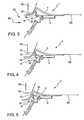
- Figures 3,4 and 5 show the retaining clip 1 attached to a sub-assembly 28 and fitted into an aperture 32 in a housing 30 (a part of which is shown). The retaining clip 1 is fitted to the sub-assembly 28 prior to fitting the sub-assembly 28 into the housing 30.
- Figures 3,4 and 5 show the retaining clip 1 in three engaged positions. Figure 4 shows a normal engaged position, whilst Figures 3 and 5 show the engaged positions that may occur with changes in tolerances, with small gaps ( Figure 3) and with large gaps ( Figure 5).
- the sub-assembly 28 is fitted into the housing 30 by pressing the sub-assembly 28 in a first direction into the aperture 32 substantially along an assembly axis 36.
- the flexible member 4 makes contact with an edge 34 of the housing 30 and flexes towards the closed position to allow the sub-assembly 28 to pass into the aperture 32.
- the retaining clip 1 opens until the engaging portion 12 contacts the edge 34 of the housing 30.
- the retaining clip 1 then prevents the sub-assembly 28 from being removed from the housing 30.
- the support post 16 contacts the guide arm 18 and substantially prevents the engaging portion 12 from moving along the first axis 36 if a removal force is exerted upon the sub-assembly 28 substantially along the assembly axis in a direction to remove the subassembly 28 from the aperture 32.
- the engaging portion 12 is substantially prevented from moving along the first axis 36 because the support means 6 allow the removal force to be transmitted directly from the engaging portion 12 to the base member 2 without passing via the flexible member 4.
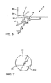
- Figure 6 shows the retaining clip 1 in the removal position, or the closed position.
- a force is applied to the override portion 14 that causes the flexible member 4 to flex towards the closed position. Once the engaging portion 12 no longer contacts the edge 34 of the aperture 32, the sub-assembly 28 can be removed from the housing 30.
- Figure 7 shows a close-up of the engaging portion 112 of a retaining clip according to a second embodiment of the engaging portion 112 of a retaining clip according to the invention.
- the engaging portion 112 of the clip includes steps or jagged portions that facilitate a strong engagement with the edge 34 of an aperture 32.
Landscapes
- Engineering & Computer Science (AREA)
- Mechanical Engineering (AREA)
- Chemical & Material Sciences (AREA)
- Combustion & Propulsion (AREA)
- Transportation (AREA)
- General Engineering & Computer Science (AREA)
- Insertion Pins And Rivets (AREA)
- Connection Of Plates (AREA)
Abstract
Description
- The present invention relates to a retaining clip, especially to a retaining clip for retaining an instrument cluster in an instrument panel in an automobile.
- When working with large moulded plastic assemblies the manufacturing tolerances possible from the moulded parts may make it difficult to use standard clips to secure the subassemblies together. If there is a large variation in the sizes of the subassemblies, a clip would require a large movement to account for these variations and this may lead to the clip being weak. The large movement of the clip may lead to the retaining force of the clip being low.
- It is common in such circumstances to use one or more screws to secure the subassemblies in place. The use of screws increases the number of parts that are used during assembly and this increases the assembly time and hence costs. The possibility of errors being made is also increased. If a screw is not fitted or is fitted incorrectly the assembly may be rejected by quality control and either discarded or disassembled which can increase costs.
- It is an object of the invention to provide a retaining clip that address some of the above issues.
- According to the invention there is provided a assembly for an automobile, the assembly comprising a housing, and a sub-assembly, the housing having an aperture therethrough said aperture having an edge, the sub-assembly being mounted within the housing by inserting the sub assembly into the aperture in an insertion direction along an assembly axis, and the sub-assembly comprising at least one retaining clip by which the sub-assembly is mounted to the housing, the retaining clip extending along assembly axis and having base member, a flexible member, an engaging portion and a support means, wherein:
- a) the base member is attached to the sub-assembly;
- b) the flexible member has a fixed and a movable end, the fixed end being attached to the base member and the flexible member extending from the fixed end towards the movable end at an acute angle relative to the assembly axis and towards the edge of the aperture;
- c) the movable end of the flexible member carries the engaging portion which extends from the flexible member towards the assembly axis;
- d) the flexible member is biased towards an open position away from the assembly axis so that during insertion of the sub-assembly into the aperture, the flexible member contacts the edge of the aperture and is thereby forced towards the assembly axis until the engaging portion engages the edge of the aperture to mount the sub-assembly within the housing and to retain the sub-assembly within the housing against a removal force applied to the sub-assembly opposite the insertion direction;
- e) the support means is arranged between the engaging portion and the base member, the support means serving in use to resist deflection of the engaging portion in response to a removal force applied to the sub-assembly and thereby maintain engagement of the engaging portion with the edge of the aperture.
-
- Providing the clip with support means that couple the engaging portion to the base member permits a removal force to be transmitted from the engaging portion to the base member via the support means without passing through the fixed end of the flexible member. This allows the clip to withstand greater removal forces without the flexible member or engaging portion buckling and therefore increases the retention force of the retaining clip. This increase in retention force allows the clip to have a wider range of movement of the engaging portion to allow for greater variations in manufacturing.
- The currently preferred form of the support means includes a support post extending from the base member and a guide arm that slidably engages with the support post to permit a removal force to be transmitted from the engaging portion to the base member without passing through the fixed end of the flexible member.
- The retaining clip is preferably moulded from a plastic material and is preferably moulded with the flexible member and the engaging portion in the open position as this will automatically bias the retaining clip to the open position. The support means are preferably arranged such that they only couple the engaging portion to the base member when the flexible member has been deflected towards the base member from the open position.
- The clip may include an integral delivery lock that can be engaged after manufacture. The retaining clip may be damaged if the flexible member is forced too far from the base member and the delivery lock is arranged to prevent the flexible member from being moved away from the base member beyond a predetermined limit. In the preferred embodiment the delivery lock comprises a hook formed on the guide arm that can be engaged with the support post by moving the engaging portion towards the base member.
- After manufacture the delivery lock can be engaged to prevent damage to the retaining clip during transit. If the retaining clip is to be used on site then this may not be required.
- To facilitate the engagement of the engaging portion of the retaining clip with an edge of the housing or subassembly the engaging portion may have a ridged or jagged surface that engages the edge. It is preferred that the retaining clip is attached to the subassembly and the engaging portion engages the edge of an aperture in the housing as this facilitates assembly.
- An assembly according to the present invention is particularly suitable for use where the subassembly is an instrument cluster and the housing is an instrument panel.
- The invention will now be further described, by way of example, with reference to the accompanying drawings, in which:
- Figure 1 shows a retaining clip according to a preferred embodiment of the invention in the open position;
- Figure 2 shows the retaining clip of Figure 1 in the delivery position;
- Figures 3,4 and 5 show the retaining clip of Figure 1 in use in three different positions;
- Figure 6 shows the retaining clip of Figure 1 in the extraction or closed position; and
- Figure 7 shows a close-up of the engaging portion of a retaining clip according to a second embodiment of the invention.
-
- Figure 1 shows a moulded
plastic retaining clip 1 in an open position according to a preferred embodiment of the present invention. Theretaining clip 1 comprises abase member 2, aflexible member 4 and support means 6. A fixedend 8 of theflexible member 4 is attached to thebase member 2. Asecond end 10 of theflexible member 4 carries anengaging portion 12 that extends transverse to theflexible member 4. Theretaining clip 1 is moulded with theengaging portion 12 in an open position away from thebase member 2. Theflexible member 4 can be flexed to move themovable end 10 closer to, or further from thebase member 2. Theflexible member 4 is biased to return to the open position in which it was moulded. When theflexible member 4 is flexed, theengaging portion 12 moves substantially in an arc about the fixedend 8 of theflexible member 4. - The
base member 2 comprises projections andprotrusions 26 that facilitate connection of theclip 1 to a sub-assembly (not shown). - The
retaining clip 1 further comprises anoverride portion 14 extending from theengagement portion 12 to allow manual or mechanical movement of the second end of theflexible member 4. - The support means 6 comprise a
support post 16 extending in first direction from thebase member 2 and aguide arm 18 extending fromengagement portion 12 in a second direction substantially perpendicular to the first direction. Adistal end 20 of theguide arm 18 is formed into ahook 22 that may be engaged over asupport end 24 of thesupport post 16 by moving the flexible member towards the closed position. Once thehook 22 has been engaged over thesupport end 24 theclip 1 is retained in a delivery position as shown in Figure 2. - Figure 2 shows the
clip 1 in the delivery position. The engagement of thehook 22 with thesupport end 24 prevents theflexible member 4 being moved away from thebase member 2, but permits theflexible member 4 to be moved towards thebase member 2. Preventing theflexible member 4 from being moved away from thebase member 2 helps to prevent damage to the retainingclip 1 that may be caused if theflexible member 4 is flexed too far from thebase member 2. The delivery position as shown in Figure 2 is therefore safer for transportation of theretaining clip 1. - Figures 3,4 and 5 show the
retaining clip 1 attached to asub-assembly 28 and fitted into anaperture 32 in a housing 30 (a part of which is shown). Theretaining clip 1 is fitted to thesub-assembly 28 prior to fitting thesub-assembly 28 into thehousing 30. Figures 3,4 and 5 show the retainingclip 1 in three engaged positions. Figure 4 shows a normal engaged position, whilst Figures 3 and 5 show the engaged positions that may occur with changes in tolerances, with small gaps (Figure 3) and with large gaps (Figure 5). - Once the
retaining clip 1 is attached to thesub-assembly 28, thesub-assembly 28 is fitted into thehousing 30 by pressing thesub-assembly 28 in a first direction into theaperture 32 substantially along anassembly axis 36. As thesub-assembly 28 passes into theaperture 32, theflexible member 4 makes contact with anedge 34 of thehousing 30 and flexes towards the closed position to allow thesub-assembly 28 to pass into theaperture 32. - When the
sub-assembly 28 has passed into theaperture 32 sufficiently for themovable end 10 of theflexible member 4 to pass theedge 34 of the housing the retainingclip 1 opens until theengaging portion 12 contacts theedge 34 of thehousing 30. The retainingclip 1 then prevents thesub-assembly 28 from being removed from thehousing 30. Thesupport post 16 contacts theguide arm 18 and substantially prevents theengaging portion 12 from moving along thefirst axis 36 if a removal force is exerted upon thesub-assembly 28 substantially along the assembly axis in a direction to remove thesubassembly 28 from theaperture 32. Theengaging portion 12 is substantially prevented from moving along thefirst axis 36 because the support means 6 allow the removal force to be transmitted directly from theengaging portion 12 to thebase member 2 without passing via theflexible member 4. - Figure 6 shows the
retaining clip 1 in the removal position, or the closed position. A force is applied to theoverride portion 14 that causes theflexible member 4 to flex towards the closed position. Once theengaging portion 12 no longer contacts theedge 34 of theaperture 32, thesub-assembly 28 can be removed from thehousing 30. - Figure 7 shows a close-up of the engaging
portion 112 of a retaining clip according to a second embodiment of the engagingportion 112 of a retaining clip according to the invention. In this case, the engagingportion 112 of the clip includes steps or jagged portions that facilitate a strong engagement with theedge 34 of anaperture 32. - The present invention has been described above purely by way of example. It should be noted that modifications in detail may be made within the scope of the invention as defined in the claims.
Claims (10)
- An assembly for an automobile, the assembly comprising a housing, and a sub-assembly, the housing having an aperture therethrough said aperture having an edge, the sub-assembly being mounted within the housing by inserting the sub assembly into the aperture in an insertion direction along an assembly axis, and the sub-assembly comprising at least one retaining clip by which the sub-assembly is mounted to the housing, the retaining clip extending along assembly axis and having base member, a flexible member, an engaging portion and a support means, wherein:a) the base member is attached to the sub-assembly;b) the flexible member has a fixed and a movable end, the fixed end being attached to the base member and the flexible member extending from the fixed end towards the movable end at an acute angle relative to the assembly axis and towards the edge of the aperture;c) the movable end of the flexible member carries the engaging portion which extends from the flexible member towards the assembly axis;d) the flexible member is biased towards an open position away from the assembly axis so that during insertion of the sub-assembly into the aperture, the flexible member contacts the edge of the aperture and is thereby forced towards the assembly axis until the engaging portion engages the edge of the aperture to mount the sub-assembly within the housing and to retain the sub-assembly within the housing against a removal force applied to the sub-assembly opposite the insertion direction;e) the support means is arranged between the engaging portion and the base member, the support means serving in use to resist deflection of the engaging portion in response to a removal force applied to the sub-assembly and thereby maintain engagement of the engaging portion with the edge of the aperture.
- An assembly as claimed in claim 1, in which the subassembly is an instrument cluster and the housing is an instrument panel.
- An assembly as claimed in claim 1 or claim 2 in which the support means comprise a support post extending from the base member and a guide arm extending from the engaging means, the guide arm slidably engaging with the support post.
- An assembly as claimed in any preceding claim, in which the retaining clip is moulded from plastic.
- An assembly as claimed in claim 4, in which the retaining clip is moulded in the open position.
- An assembly as claimed in any preceding claim, in which the retaining clip includes a delivery lock that may be engaged by forcing the flexible member towards the base member from the open position, once engaged, the delivery lock preventing the retaining clip from being opened beyond a predetermined limit.
- An assembly as claimed in claim 6, in which the delivery lock comprises a hook formed on the guide arm that can be engaged with the support post to prevent the retaining clip from being opened beyond the predetermined limit.
- An assembly as claimed in any preceding claim, in which the engaging portion has a ridged surface that engages with the edge of the aperture.
- An assembly as claimed in any preceding claim, in which the retaining clip further comprises an override portion that extends from the engaging portion to permit manual or mechanical movement of the engaging portion.
- A retaining clip for use in the assembly of claim 1, wherein the retaining clip extends along assembly axis and has a base member, a flexible member, an engaging portion and a support means.
Applications Claiming Priority (2)
| Application Number | Priority Date | Filing Date | Title |
|---|---|---|---|
| GB0220283A GB2392473B (en) | 2002-08-31 | 2002-08-31 | Retaining clip |
| GB0220283 | 2002-08-31 |
Publications (1)
| Publication Number | Publication Date |
|---|---|
| EP1393958A1 true EP1393958A1 (en) | 2004-03-03 |
Family
ID=9943295
Family Applications (1)
| Application Number | Title | Priority Date | Filing Date |
|---|---|---|---|
| EP03254955A Withdrawn EP1393958A1 (en) | 2002-08-31 | 2003-08-08 | Retaining clip |
Country Status (2)
| Country | Link |
|---|---|
| EP (1) | EP1393958A1 (en) |
| GB (1) | GB2392473B (en) |
Citations (1)
| Publication number | Priority date | Publication date | Assignee | Title |
|---|---|---|---|---|
| EP0682184A1 (en) * | 1994-05-11 | 1995-11-15 | Automobiles Peugeot | Improved elastic attachment |
Family Cites Families (1)
| Publication number | Priority date | Publication date | Assignee | Title |
|---|---|---|---|---|
| GB2337393B (en) * | 1998-05-12 | 2000-04-05 | Vtech Communications Ltd | Portable telephone handset construction |
-
2002
- 2002-08-31 GB GB0220283A patent/GB2392473B/en not_active Expired - Fee Related
-
2003
- 2003-08-08 EP EP03254955A patent/EP1393958A1/en not_active Withdrawn
Patent Citations (1)
| Publication number | Priority date | Publication date | Assignee | Title |
|---|---|---|---|---|
| EP0682184A1 (en) * | 1994-05-11 | 1995-11-15 | Automobiles Peugeot | Improved elastic attachment |
Also Published As
| Publication number | Publication date |
|---|---|
| GB2392473A (en) | 2004-03-03 |
| GB2392473B (en) | 2004-07-14 |
| GB0220283D0 (en) | 2002-10-09 |
Similar Documents
| Publication | Publication Date | Title |
|---|---|---|
| US6325647B1 (en) | Electrical plug connector | |
| US5033972A (en) | Electrical connector | |
| US7538283B2 (en) | Switch device and assembly method thereof | |
| US7553188B2 (en) | Slide lock panel-mount connector | |
| US20200194932A1 (en) | Plug connector including a profiled latch | |
| CN107069349B (en) | Electrical plug-in connection and release element therefor | |
| EP1312521B1 (en) | Sensor device | |
| US7140653B2 (en) | Outside handle apparatus and connector mechanism | |
| EP0901197B1 (en) | Self-aligning connector system for electrical connectors | |
| EP1049216A2 (en) | Panel mounted connector | |
| US7536989B2 (en) | Fuel tank cover body | |
| CN114269605B (en) | windshield | |
| CN111834788B (en) | Electrical terminal housing with terminal lock | |
| JP3114486B2 (en) | connector | |
| GB2392473A (en) | Retaining clip | |
| US5336861A (en) | Switch with removable button frame | |
| EP0901189A2 (en) | Mounting system for an electrical connector assembly | |
| US12482616B2 (en) | Input device | |
| WO2010058529A1 (en) | Electric connector and electric connector assembly | |
| US5323297A (en) | Twist-in mounting for electromechanical component | |
| JPH087971A (en) | Connector for circuit board | |
| JP3851133B2 (en) | Clamp | |
| US5944560A (en) | Frame structure for mounting an electrical connector | |
| EP3552885A1 (en) | Composite component for a motor vehicle | |
| JP2663917B2 (en) | Mounting mechanism of the body to be mounted |
Legal Events
| Date | Code | Title | Description |
|---|---|---|---|
| PUAI | Public reference made under article 153(3) epc to a published international application that has entered the european phase |
Free format text: ORIGINAL CODE: 0009012 |
|
| AK | Designated contracting states |
Kind code of ref document: A1 Designated state(s): AT BE BG CH CY CZ DE DK EE ES FI FR GB GR HU IE IT LI LU MC NL PT RO SE SI SK TR |
|
| AX | Request for extension of the european patent |
Extension state: AL LT LV MK |
|
| 17P | Request for examination filed |
Effective date: 20040427 |
|
| AKX | Designation fees paid |
Designated state(s): DE ES FR GB TR |
|
| 17Q | First examination report despatched |
Effective date: 20041102 |
|
| GRAP | Despatch of communication of intention to grant a patent |
Free format text: ORIGINAL CODE: EPIDOSNIGR1 |
|
| STAA | Information on the status of an ep patent application or granted ep patent |
Free format text: STATUS: THE APPLICATION IS DEEMED TO BE WITHDRAWN |
|
| 18D | Application deemed to be withdrawn |
Effective date: 20071216 |