EP1393696A1 - Ankle fusion guide and method - Google Patents
Ankle fusion guide and method Download PDFInfo
- Publication number
- EP1393696A1 EP1393696A1 EP03255220A EP03255220A EP1393696A1 EP 1393696 A1 EP1393696 A1 EP 1393696A1 EP 03255220 A EP03255220 A EP 03255220A EP 03255220 A EP03255220 A EP 03255220A EP 1393696 A1 EP1393696 A1 EP 1393696A1
- Authority
- EP
- European Patent Office
- Prior art keywords
- guide
- tibia
- talus
- ankle
- instrument
- Prior art date
- Legal status (The legal status is an assumption and is not a legal conclusion. Google has not performed a legal analysis and makes no representation as to the accuracy of the status listed.)
- Withdrawn
Links
- 210000003423 ankle Anatomy 0.000 title claims abstract description 105
- 230000004927 fusion Effects 0.000 title claims abstract description 66
- 238000000034 method Methods 0.000 title description 50
- 210000002303 tibia Anatomy 0.000 claims abstract description 116
- 210000004233 talus Anatomy 0.000 claims abstract description 91
- 210000000988 bone and bone Anatomy 0.000 claims abstract description 48
- 238000002271 resection Methods 0.000 claims description 40
- 238000005520 cutting process Methods 0.000 claims description 25
- 238000011882 arthroplasty Methods 0.000 claims description 13
- 210000004872 soft tissue Anatomy 0.000 description 13
- 238000001356 surgical procedure Methods 0.000 description 13
- 239000007943 implant Substances 0.000 description 11
- 210000002414 leg Anatomy 0.000 description 10
- 210000000544 articulatio talocruralis Anatomy 0.000 description 7
- 210000002082 fibula Anatomy 0.000 description 4
- 239000000463 material Substances 0.000 description 4
- 230000005021 gait Effects 0.000 description 3
- 210000001503 joint Anatomy 0.000 description 3
- 229910052751 metal Inorganic materials 0.000 description 3
- 239000002184 metal Substances 0.000 description 3
- 201000008482 osteoarthritis Diseases 0.000 description 3
- 208000037873 arthrodesis Diseases 0.000 description 2
- 210000000459 calcaneus Anatomy 0.000 description 2
- 239000011248 coating agent Substances 0.000 description 2
- 238000000576 coating method Methods 0.000 description 2
- 238000003754 machining Methods 0.000 description 2
- 238000004519 manufacturing process Methods 0.000 description 2
- 230000007935 neutral effect Effects 0.000 description 2
- 206010039073 rheumatoid arthritis Diseases 0.000 description 2
- 230000006641 stabilisation Effects 0.000 description 2
- 238000011105 stabilization Methods 0.000 description 2
- 229910000851 Alloy steel Inorganic materials 0.000 description 1
- 229910000684 Cobalt-chrome Inorganic materials 0.000 description 1
- 239000004698 Polyethylene Substances 0.000 description 1
- 229910000831 Steel Inorganic materials 0.000 description 1
- RTAQQCXQSZGOHL-UHFFFAOYSA-N Titanium Chemical compound [Ti] RTAQQCXQSZGOHL-UHFFFAOYSA-N 0.000 description 1
- 239000000956 alloy Substances 0.000 description 1
- 230000004075 alteration Effects 0.000 description 1
- 230000003466 anti-cipated effect Effects 0.000 description 1
- 206010003246 arthritis Diseases 0.000 description 1
- 239000004568 cement Substances 0.000 description 1
- 239000000919 ceramic Substances 0.000 description 1
- 239000010952 cobalt-chrome Substances 0.000 description 1
- 230000001010 compromised effect Effects 0.000 description 1
- 230000003111 delayed effect Effects 0.000 description 1
- 238000007599 discharging Methods 0.000 description 1
- 210000004744 fore-foot Anatomy 0.000 description 1
- 230000035876 healing Effects 0.000 description 1
- 210000000548 hind-foot Anatomy 0.000 description 1
- 239000011325 microbead Substances 0.000 description 1
- 230000000399 orthopedic effect Effects 0.000 description 1
- -1 polyethylene Polymers 0.000 description 1
- 229920000573 polyethylene Polymers 0.000 description 1
- 229910001220 stainless steel Inorganic materials 0.000 description 1
- 239000010935 stainless steel Substances 0.000 description 1
- 239000010959 steel Substances 0.000 description 1
- 238000006467 substitution reaction Methods 0.000 description 1
- 238000004381 surface treatment Methods 0.000 description 1
- 239000010936 titanium Substances 0.000 description 1
- 229910052719 titanium Inorganic materials 0.000 description 1
Images




Classifications
-
- A—HUMAN NECESSITIES
- A61—MEDICAL OR VETERINARY SCIENCE; HYGIENE
- A61B—DIAGNOSIS; SURGERY; IDENTIFICATION
- A61B17/00—Surgical instruments, devices or methods
- A61B17/14—Surgical saws
- A61B17/15—Guides therefor
-
- A—HUMAN NECESSITIES
- A61—MEDICAL OR VETERINARY SCIENCE; HYGIENE
- A61B—DIAGNOSIS; SURGERY; IDENTIFICATION
- A61B17/00—Surgical instruments, devices or methods
- A61B17/16—Instruments for performing osteoclasis; Drills or chisels for bones; Trepans
- A61B17/17—Guides or aligning means for drills, mills, pins or wires
- A61B17/1739—Guides or aligning means for drills, mills, pins or wires specially adapted for particular parts of the body
- A61B17/1775—Guides or aligning means for drills, mills, pins or wires specially adapted for particular parts of the body for the foot or ankle
-
- A—HUMAN NECESSITIES
- A61—MEDICAL OR VETERINARY SCIENCE; HYGIENE
- A61F—FILTERS IMPLANTABLE INTO BLOOD VESSELS; PROSTHESES; DEVICES PROVIDING PATENCY TO, OR PREVENTING COLLAPSING OF, TUBULAR STRUCTURES OF THE BODY, e.g. STENTS; ORTHOPAEDIC, NURSING OR CONTRACEPTIVE DEVICES; FOMENTATION; TREATMENT OR PROTECTION OF EYES OR EARS; BANDAGES, DRESSINGS OR ABSORBENT PADS; FIRST-AID KITS
- A61F2/00—Filters implantable into blood vessels; Prostheses, i.e. artificial substitutes or replacements for parts of the body; Appliances for connecting them with the body; Devices providing patency to, or preventing collapsing of, tubular structures of the body, e.g. stents
- A61F2/02—Prostheses implantable into the body
- A61F2/30—Joints
- A61F2/42—Joints for wrists or ankles; for hands, e.g. fingers; for feet, e.g. toes
- A61F2/4202—Joints for wrists or ankles; for hands, e.g. fingers; for feet, e.g. toes for ankles
-
- A—HUMAN NECESSITIES
- A61—MEDICAL OR VETERINARY SCIENCE; HYGIENE
- A61B—DIAGNOSIS; SURGERY; IDENTIFICATION
- A61B17/00—Surgical instruments, devices or methods
- A61B17/02—Surgical instruments, devices or methods for holding wounds open, e.g. retractors; Tractors
- A61B17/025—Joint distractors
-
- A—HUMAN NECESSITIES
- A61—MEDICAL OR VETERINARY SCIENCE; HYGIENE
- A61B—DIAGNOSIS; SURGERY; IDENTIFICATION
- A61B17/00—Surgical instruments, devices or methods
- A61B17/14—Surgical saws
- A61B17/142—Surgical saws with reciprocating saw blades, e.g. with cutting edges at the distal end of the saw blades
-
- A—HUMAN NECESSITIES
- A61—MEDICAL OR VETERINARY SCIENCE; HYGIENE
- A61B—DIAGNOSIS; SURGERY; IDENTIFICATION
- A61B17/00—Surgical instruments, devices or methods
- A61B17/56—Surgical instruments or methods for treatment of bones or joints; Devices specially adapted therefor
- A61B17/58—Surgical instruments or methods for treatment of bones or joints; Devices specially adapted therefor for osteosynthesis, e.g. bone plates, screws or setting implements
- A61B17/68—Internal fixation devices, including fasteners and spinal fixators, even if a part thereof projects from the skin
- A61B17/72—Intramedullary devices, e.g. pins or nails
-
- A—HUMAN NECESSITIES
- A61—MEDICAL OR VETERINARY SCIENCE; HYGIENE
- A61B—DIAGNOSIS; SURGERY; IDENTIFICATION
- A61B17/00—Surgical instruments, devices or methods
- A61B17/56—Surgical instruments or methods for treatment of bones or joints; Devices specially adapted therefor
- A61B17/58—Surgical instruments or methods for treatment of bones or joints; Devices specially adapted therefor for osteosynthesis, e.g. bone plates, screws or setting implements
- A61B17/68—Internal fixation devices, including fasteners and spinal fixators, even if a part thereof projects from the skin
- A61B17/72—Intramedullary devices, e.g. pins or nails
- A61B17/7291—Intramedullary devices, e.g. pins or nails for small bones, e.g. in the foot, ankle, hand or wrist
-
- A—HUMAN NECESSITIES
- A61—MEDICAL OR VETERINARY SCIENCE; HYGIENE
- A61B—DIAGNOSIS; SURGERY; IDENTIFICATION
- A61B17/00—Surgical instruments, devices or methods
- A61B17/56—Surgical instruments or methods for treatment of bones or joints; Devices specially adapted therefor
- A61B17/58—Surgical instruments or methods for treatment of bones or joints; Devices specially adapted therefor for osteosynthesis, e.g. bone plates, screws or setting implements
- A61B17/68—Internal fixation devices, including fasteners and spinal fixators, even if a part thereof projects from the skin
- A61B17/80—Cortical plates, i.e. bone plates; Instruments for holding or positioning cortical plates, or for compressing bones attached to cortical plates
- A61B17/8061—Cortical plates, i.e. bone plates; Instruments for holding or positioning cortical plates, or for compressing bones attached to cortical plates specially adapted for particular bones
-
- A—HUMAN NECESSITIES
- A61—MEDICAL OR VETERINARY SCIENCE; HYGIENE
- A61F—FILTERS IMPLANTABLE INTO BLOOD VESSELS; PROSTHESES; DEVICES PROVIDING PATENCY TO, OR PREVENTING COLLAPSING OF, TUBULAR STRUCTURES OF THE BODY, e.g. STENTS; ORTHOPAEDIC, NURSING OR CONTRACEPTIVE DEVICES; FOMENTATION; TREATMENT OR PROTECTION OF EYES OR EARS; BANDAGES, DRESSINGS OR ABSORBENT PADS; FIRST-AID KITS
- A61F2/00—Filters implantable into blood vessels; Prostheses, i.e. artificial substitutes or replacements for parts of the body; Appliances for connecting them with the body; Devices providing patency to, or preventing collapsing of, tubular structures of the body, e.g. stents
- A61F2/02—Prostheses implantable into the body
- A61F2/30—Joints
- A61F2/30767—Special external or bone-contacting surface, e.g. coating for improving bone ingrowth
-
- A—HUMAN NECESSITIES
- A61—MEDICAL OR VETERINARY SCIENCE; HYGIENE
- A61F—FILTERS IMPLANTABLE INTO BLOOD VESSELS; PROSTHESES; DEVICES PROVIDING PATENCY TO, OR PREVENTING COLLAPSING OF, TUBULAR STRUCTURES OF THE BODY, e.g. STENTS; ORTHOPAEDIC, NURSING OR CONTRACEPTIVE DEVICES; FOMENTATION; TREATMENT OR PROTECTION OF EYES OR EARS; BANDAGES, DRESSINGS OR ABSORBENT PADS; FIRST-AID KITS
- A61F2/00—Filters implantable into blood vessels; Prostheses, i.e. artificial substitutes or replacements for parts of the body; Appliances for connecting them with the body; Devices providing patency to, or preventing collapsing of, tubular structures of the body, e.g. stents
- A61F2/02—Prostheses implantable into the body
- A61F2/30—Joints
- A61F2/3094—Designing or manufacturing processes
- A61F2/30942—Designing or manufacturing processes for designing or making customized prostheses, e.g. using templates, CT or NMR scans, finite-element analysis or CAD-CAM techniques
-
- A—HUMAN NECESSITIES
- A61—MEDICAL OR VETERINARY SCIENCE; HYGIENE
- A61F—FILTERS IMPLANTABLE INTO BLOOD VESSELS; PROSTHESES; DEVICES PROVIDING PATENCY TO, OR PREVENTING COLLAPSING OF, TUBULAR STRUCTURES OF THE BODY, e.g. STENTS; ORTHOPAEDIC, NURSING OR CONTRACEPTIVE DEVICES; FOMENTATION; TREATMENT OR PROTECTION OF EYES OR EARS; BANDAGES, DRESSINGS OR ABSORBENT PADS; FIRST-AID KITS
- A61F2/00—Filters implantable into blood vessels; Prostheses, i.e. artificial substitutes or replacements for parts of the body; Appliances for connecting them with the body; Devices providing patency to, or preventing collapsing of, tubular structures of the body, e.g. stents
- A61F2/02—Prostheses implantable into the body
- A61F2/30—Joints
- A61F2002/30001—Additional features of subject-matter classified in A61F2/28, A61F2/30 and subgroups thereof
- A61F2002/30316—The prosthesis having different structural features at different locations within the same prosthesis; Connections between prosthetic parts; Special structural features of bone or joint prostheses not otherwise provided for
- A61F2002/30535—Special structural features of bone or joint prostheses not otherwise provided for
- A61F2002/30604—Special structural features of bone or joint prostheses not otherwise provided for modular
- A61F2002/30616—Sets comprising a plurality of prosthetic parts of different sizes or orientations
-
- A—HUMAN NECESSITIES
- A61—MEDICAL OR VETERINARY SCIENCE; HYGIENE
- A61F—FILTERS IMPLANTABLE INTO BLOOD VESSELS; PROSTHESES; DEVICES PROVIDING PATENCY TO, OR PREVENTING COLLAPSING OF, TUBULAR STRUCTURES OF THE BODY, e.g. STENTS; ORTHOPAEDIC, NURSING OR CONTRACEPTIVE DEVICES; FOMENTATION; TREATMENT OR PROTECTION OF EYES OR EARS; BANDAGES, DRESSINGS OR ABSORBENT PADS; FIRST-AID KITS
- A61F2/00—Filters implantable into blood vessels; Prostheses, i.e. artificial substitutes or replacements for parts of the body; Appliances for connecting them with the body; Devices providing patency to, or preventing collapsing of, tubular structures of the body, e.g. stents
- A61F2/02—Prostheses implantable into the body
- A61F2/30—Joints
- A61F2002/30001—Additional features of subject-matter classified in A61F2/28, A61F2/30 and subgroups thereof
- A61F2002/30621—Features concerning the anatomical functioning or articulation of the prosthetic joint
- A61F2002/30622—Implant for fusing a joint or bone material
-
- A—HUMAN NECESSITIES
- A61—MEDICAL OR VETERINARY SCIENCE; HYGIENE
- A61F—FILTERS IMPLANTABLE INTO BLOOD VESSELS; PROSTHESES; DEVICES PROVIDING PATENCY TO, OR PREVENTING COLLAPSING OF, TUBULAR STRUCTURES OF THE BODY, e.g. STENTS; ORTHOPAEDIC, NURSING OR CONTRACEPTIVE DEVICES; FOMENTATION; TREATMENT OR PROTECTION OF EYES OR EARS; BANDAGES, DRESSINGS OR ABSORBENT PADS; FIRST-AID KITS
- A61F2/00—Filters implantable into blood vessels; Prostheses, i.e. artificial substitutes or replacements for parts of the body; Appliances for connecting them with the body; Devices providing patency to, or preventing collapsing of, tubular structures of the body, e.g. stents
- A61F2/02—Prostheses implantable into the body
- A61F2/30—Joints
- A61F2/30767—Special external or bone-contacting surface, e.g. coating for improving bone ingrowth
- A61F2/30771—Special external or bone-contacting surface, e.g. coating for improving bone ingrowth applied in original prostheses, e.g. holes or grooves
- A61F2002/30878—Special external or bone-contacting surface, e.g. coating for improving bone ingrowth applied in original prostheses, e.g. holes or grooves with non-sharp protrusions, for instance contacting the bone for anchoring, e.g. keels, pegs, pins, posts, shanks, stems, struts
-
- A—HUMAN NECESSITIES
- A61—MEDICAL OR VETERINARY SCIENCE; HYGIENE
- A61F—FILTERS IMPLANTABLE INTO BLOOD VESSELS; PROSTHESES; DEVICES PROVIDING PATENCY TO, OR PREVENTING COLLAPSING OF, TUBULAR STRUCTURES OF THE BODY, e.g. STENTS; ORTHOPAEDIC, NURSING OR CONTRACEPTIVE DEVICES; FOMENTATION; TREATMENT OR PROTECTION OF EYES OR EARS; BANDAGES, DRESSINGS OR ABSORBENT PADS; FIRST-AID KITS
- A61F2/00—Filters implantable into blood vessels; Prostheses, i.e. artificial substitutes or replacements for parts of the body; Appliances for connecting them with the body; Devices providing patency to, or preventing collapsing of, tubular structures of the body, e.g. stents
- A61F2/02—Prostheses implantable into the body
- A61F2/30—Joints
- A61F2/3094—Designing or manufacturing processes
- A61F2002/30968—Sintering
-
- A—HUMAN NECESSITIES
- A61—MEDICAL OR VETERINARY SCIENCE; HYGIENE
- A61F—FILTERS IMPLANTABLE INTO BLOOD VESSELS; PROSTHESES; DEVICES PROVIDING PATENCY TO, OR PREVENTING COLLAPSING OF, TUBULAR STRUCTURES OF THE BODY, e.g. STENTS; ORTHOPAEDIC, NURSING OR CONTRACEPTIVE DEVICES; FOMENTATION; TREATMENT OR PROTECTION OF EYES OR EARS; BANDAGES, DRESSINGS OR ABSORBENT PADS; FIRST-AID KITS
- A61F2/00—Filters implantable into blood vessels; Prostheses, i.e. artificial substitutes or replacements for parts of the body; Appliances for connecting them with the body; Devices providing patency to, or preventing collapsing of, tubular structures of the body, e.g. stents
- A61F2/02—Prostheses implantable into the body
- A61F2/30—Joints
- A61F2/42—Joints for wrists or ankles; for hands, e.g. fingers; for feet, e.g. toes
- A61F2/4202—Joints for wrists or ankles; for hands, e.g. fingers; for feet, e.g. toes for ankles
- A61F2002/4205—Tibial components
-
- A—HUMAN NECESSITIES
- A61—MEDICAL OR VETERINARY SCIENCE; HYGIENE
- A61F—FILTERS IMPLANTABLE INTO BLOOD VESSELS; PROSTHESES; DEVICES PROVIDING PATENCY TO, OR PREVENTING COLLAPSING OF, TUBULAR STRUCTURES OF THE BODY, e.g. STENTS; ORTHOPAEDIC, NURSING OR CONTRACEPTIVE DEVICES; FOMENTATION; TREATMENT OR PROTECTION OF EYES OR EARS; BANDAGES, DRESSINGS OR ABSORBENT PADS; FIRST-AID KITS
- A61F2/00—Filters implantable into blood vessels; Prostheses, i.e. artificial substitutes or replacements for parts of the body; Appliances for connecting them with the body; Devices providing patency to, or preventing collapsing of, tubular structures of the body, e.g. stents
- A61F2/02—Prostheses implantable into the body
- A61F2/30—Joints
- A61F2/42—Joints for wrists or ankles; for hands, e.g. fingers; for feet, e.g. toes
- A61F2/4202—Joints for wrists or ankles; for hands, e.g. fingers; for feet, e.g. toes for ankles
- A61F2002/4207—Talar components
-
- A—HUMAN NECESSITIES
- A61—MEDICAL OR VETERINARY SCIENCE; HYGIENE
- A61F—FILTERS IMPLANTABLE INTO BLOOD VESSELS; PROSTHESES; DEVICES PROVIDING PATENCY TO, OR PREVENTING COLLAPSING OF, TUBULAR STRUCTURES OF THE BODY, e.g. STENTS; ORTHOPAEDIC, NURSING OR CONTRACEPTIVE DEVICES; FOMENTATION; TREATMENT OR PROTECTION OF EYES OR EARS; BANDAGES, DRESSINGS OR ABSORBENT PADS; FIRST-AID KITS
- A61F2310/00—Prostheses classified in A61F2/28 or A61F2/30 - A61F2/44 being constructed from or coated with a particular material
- A61F2310/00389—The prosthesis being coated or covered with a particular material
- A61F2310/00395—Coating or prosthesis-covering structure made of metals or of alloys
Definitions
- the present invention relates generally to the field of orthopaedics, and more particularly, to an implant for use in arthroplasty.
- Osteoarthritis and rheumatoid arthritis are common afflictions of the joints of the human body.
- the ankle is one of the many joints which may be susceptible to osteoarthritis.
- Arthrodesis has been an accepted treatment for painful osteoarthritis and rheumatoid arthritis of the ankle and the subtailor joints for many years. In the most common of arthrodesis, the talus, tibia and calcaneus are fused together. Such a procedure is commonly known as an ankle fusion.
- Another less common treatment for arthritis of the ankle is total ankle arthroplasty. Total ankle arthroplasty can be described in greater detail in U.S. Patent 5,326,365 to Alvine, hereby incorporated by reference in its entirety.
- a portion of the ankle fusion procedure is to resect the distal tibia and the proximal talus.
- the resected surface of the distal tibia and the proximal talus are then fused together.
- the tibia and talus may be fused together using any of a combination of bone plates, bone screws, and intermedullary nails.
- the ankle joint is distracted approximately one centimeter. While in this distracted condition, the tibia and talus are resected. The joint is then relaxed and then the tibia and talus are fused.
- the resection of the tibia and talus are typically performed utilizing a saw blade that is held in the surgeon's hand and the resection is performed free hand.
- the free-hand resection of the tibia and talus has several problems.
- One problem with the current free-hand method of resection is the danger of over resection of the joint surfaces. If too great a resection is performed, the ankle joint height is compromised. The patient then may have a resected leg length that is unacceptably shorter than the unfused leg length.
- Another problem with the present free- hand method of resecting the tibia and talus is that fore and hind foot alignment may be inaccurate. Alignment is very important because a fused ankle has only a limited degree of flexion. Excessive dorsal flexion or plantar flexion may cause gait problems or patient pain.
- tibia and talus resection An additional problem with the use of a free hand tibia and talus resection is that the cuts may not be straight. If the cuts are not straight or are angled in or out, problems may occur with fusion. If the cuts are not straight, the contact surface between the tibia and talus may be minimal causing excessive minimal contact between the tibia and talus lengthening the healing time and jeopardizing the successfulness of the fusion. Alternatively, if the surfaces are not straight, the tibia and talus may not be properly oriented to each other causing dorsal flexion or planar flexion which may cause gait problems or pain.
- an ankle fusion guide is provided as a cutting guide for a tibial and talar resection during an ankle fusion procedure.
- the guide includes two guiding slots, one each for the tibia and talus cut.
- the guide may also include a series of pinholes to allow for stabilization of the guide during resection.
- the guide may be adapted to fit into a total ankle arthroplasty alignment jig, which would align the cutting guide to the neutral position using the tibia. Utilizing the ankle fusion guide in the total ankle arthoplasty jig would permit the surgeon to revert to an ankle fusion procedure easily and quickly when an anticipated total ankle arthroplasty may not be performed due to the deteriorated condition of the patient's bones or soft tissue.
- the top of the fusion guide may be designed with a T- shaped top that is even with the anterior face of the guide such that the posterior flush face of the guide is setting against the bone. This configuration eliminates toggling of the saw blade during the resection.
- a neutral alignment with the tibia may be provided.
- the ankle fusion guide provides a straight cutting edge for the saw blade ensuring a flat, level cut which makes the fusion easier.
- the guide may have a T shape top which may be set even to the anterior face of the guide so that the posterior face can sit flush to the bone when attached to the alignment jig. This configuration provides more accuracy during cutting.
- the ankle fusion guide may include a T shaped top, which is narrow at the base, thereby providing a smaller object to place into the wound site, which permits the surgeon to have a better view of the tibia and the talus.
- the ankle fusion cutting guide may also include pinholes, for example, four pin holes.
- the two middle pin holes may be set straight into the tibia while the other two pin holes, one medial and one lateral, are set into the tibia at an angle. The use of the pinholes assures the stability of the guide during resection.
- the middle two holes may be an equal distance from the midline of the device and may be drilled straight through at a 90 degree angle with respect to the device.
- the outer two holes may be placed medially and lateral to the middle holes and may be angled inwardly at an angle, for example, 15 degrees. All four holes may have uniform diameter so that a common drill and pin may be used.
- the ankle fusion cutting guide may include two slots on the distal portion of the base. These slots may run almost entirely the width of the guide.
- the slots may be close together and the tibial slot may have starting holes, one being medial and one being lateral.
- the starting holes guide the drill needed to start the resection and insure a smooth round edge free of stress risers.
- the talar cutting slot may not need a starting hole.
- a small hole may be located on one side of the guide and may be used to accommodate a wire for making a wire electronic discharge machine (EDM machine) with the slot. Both cutting slots are preferably thick enough for use with a common, standard saw blade.
- a kit for removal of bone from the talus and the tibia of a patient for performing ankle fusion includes a guide for cooperation with at least one of the tibia and the talus and an instrument constrainable by the guide for removal of the bone.
- a guide for guiding an instrument for the removal of bone from a first bone and a second bone of a patient for performing joint fusion between the first bone and the second bone is provided.
- the guide includes a body and a feature operably associated with the body for constraining the instrument.
- the feature can comprises a first constraint for guiding a tool for performing the first bone resection and a second constraint for guiding the tool for performing the second bone resection.
- At least one of said first constraint and said second constraint can be defined by an opening in said body.
- the opening can be defined by a slot.
- Said body can further define a hole therethrough.
- Said body can define a first through slot, a second through slot spaced from and parallel to the first slot, and a plurality of circular though holes.
- a jig for fixedly positioning a guide for guiding an instrument for the removal of bone from the talus and the tibia of a patient for performing ankle fusion.
- the guide is positioned relative to the tibia and the talus.
- the jig includes a body, a fixator for securing the tibia to the body, and an attachment for attaching the guide to the body.
- Said jig can be adapted for removably fixedly positioning said guide to said jig, and wherein said jig can be adapted for removably fixedly positioning a second guide to said j ig, said second guide can be adapted for guiding the instrument for the removal of bone from the talus and the tibia of a patient for performing total ankle arthroplasty.
- a method for providing ankle fusion surgery includes the steps of fixedly securing a talus with respect to a tibia, providing an instrument for removing bone from at least one of a talus and a tibia, providing a guide for guiding the instrument, fixedly securing the guide to the tibia, positioning the instrument in the guide, removing bone from at least one of the tibia and the talus, and fusing the tibia to the talus.
- a method for providing ankle surgery includes the steps of analyzing the condition of the tibia and the talus and adjacent soft tissue, and providing an instrument for removing bone from at least one of a talus and a tibia.
- the method also includes the steps of providing a first guide for guiding the instrument for removal of bone for performing an ankle fusion procedure, providing a second guide for guiding the instrument for removal of bone for performing an total ankle arthroplasty procedure, and fixedly securing one of the first guide and the second guide to the tibia depending on the condition of the tibia and the talus and adjacent soft tissue.
- the method further includes the steps of positioning the instrument in one of the first guide and the second guide depending on the condition of the tibia and the talus and adjacent soft tissue, removing bone from at least one of the tibia and the talus, and performing one of an ankle fusion procedure and a total ankle arthroplasty procedure depending on the condition of the tibia and the talus and adjacent soft tissue.
- the ankle fusion guide of the present invention includes two closely aligned cutting guide slots for the tibia and talus cut. A saw blade is restrained within the guiding slots for providing minimal recession of the tibia and talus.
- the present invention provides for reducing the likelihood of over-resection of the joint surfaces.
- the technical advantages of the present invention also include improved alignment of the tibia and talus resection cuts for ankle fusion.
- the improved alignment helps to minimize excessive dorsal flexion and planar flexion, which may cause gait problems or pain.
- the ankle fusion guide includes a pair of spaced-apart parallel slots for guiding a standard saw blade to perform the tibia and talus resections.
- a series of pin holes are located in the fusion guide block that are used to securely position the fusion guide block for the resection cuts.
- the ankle fusion guide includes a pair of spaced apart guiding slots to which a standard saw blade closely fits. The close fitting of the slots to the standard saw blade results in a straight cut.
- a further technical advantage of the present invention includes the ability to easily perform an ankle fusion if it appears during surgery that a total ankle replacement is not feasible.
- the ankle fusion guide is compatible with the alignment of a total ankle arthoplasty instrument set.
- the cutting guide for a total ankle replacement may be replaced with the ankle fusion guide of the present invention.
- the present invention provides for an easy method of performing an ankle fusion if it appears during surgery that a total ankle replacement is not feasible.
- a further technical advantage of the present invention is reduced toggling and misalignment of the resection of the tibia and talus during ankle fusion.
- the ankle fusion block is set even with the interior face of the guide so that the cutting slots can be set flush with the joint.
- the saw blade With the additional thickness of the guide, the saw blade has very little room to toggle or misalign.
- the present invention provides for additional support for the saw blade such that toggling is minimized.
- a kit 10 for removal of bone 12 from a talus 14 and tibia 16 of a patient 20 is shown.
- the kit 10 is utilized to perform an ankle fusion procedure.
- the kit 10 includes a guide 22 for cooperation with at least one of the tibia 16 and talus 14.
- the kit 10 further includes an instrument 24, which is constrainable, by guide 22 for removal of the bone 12.
- the guide 22 may include a body 26.
- the body 26 may define a first constraint 30 for guiding the instrument 24 for performing the tibia resection.
- the body 26 may also define a second constraint 32 for guiding the instrument 24 for performing the talus resection.
- the constraints 30 and 32 may have any suitable shape capable of guiding or controlling the instrument 24. For example, if the instrument 24 is in the form of a cutting blade, the constraints 30 and 32 may be in the form of slots.
- the first constraint or slot 30 and the second constraint or slot 32 are preferably parallel to each other and spaced from each other a distance G.
- the dimension of the distance G may be slightly larger than the amount the ankle is distracted during the resection.
- the ankle may be distracted, for example, a distance of approximately one centimeter.
- the dimension G thus, may be, for example, approximately 0.1 to 2.5 centimeters.
- the first slot 30 and the second slot 32 preferably have a width W1 and W2, respectively.
- the width is selected to permit the instrument 24 to slidably fit within the first and second slots 30 and 32.
- the instrument 24 may have a width W3 slightly smaller than the widths W1 and W2 of the slots 30 and 32.
- the first slot 30 has a width TISW which is slightly larger than the width TIW of the resected portion of the tibia.
- the second constraint 32 has a width TASW which is slightly longer than the width TAW of the resected portion of the talus 14.
- the guide 22 may include additional features to guide additional instruments and to provide for particular configuration in the resection.
- the first slot 30 may include a first relief hole 34 on one end of the first slot 30 and a second relief hole 36 opposed to the first relief hole 34.
- the relief holes 34 and 36 serve as bushings to guide second instrument 40 in the form of, for example, a drill to prepare arcuate corners in the tibia resections.
- the relief holes 34 and 36 also serve as a starting point for wire EDM (electronic discharge machining) equipment.
- the relief holes 34 and 36 are used to drill a hole through tibia 16 on the medial side of the tibia 16 with drill 40.
- the drill 40 forms arcuate surface 38 between resected surface 100 of tibia 16 and distal medial protrusions 39 of tibia 16.
- the arcuate surface 38 serves to prevent stress risers in the comers of the resected tibial bone.
- the relief holes 34 and 36 eliminate the need to run the instrument 24 all the way into the comer of the resected tibia 16.
- the first starting hole 34 and 36 are preferably matingly fitted to the drill 40. It should be appreciated that the slots 30 and 32 may not necessarily require the use of relief holes.
- the second slot 32 does not include a relief hole but merely, as shown in FIG. 2, includes a smaller hole used in manufacturing to assist in the manufacture of the guide 22 by providing a starting point for wire EDM (electronic discharging machining) equipment.
- the guide 22 may be made of any suitable durable material capable of constraining the instrument 24.
- the guide 22 may be made of a metal or ceramic.
- the guide 22 may be made of a titanium or cobalt chrome alloy or stainless steel.
- the guide 22 is made of a material that is compatible with the human body.
- the guide 22 may be positioned adjacent to the tibia 16 and talus 14 by any suitable method.
- the guide 22 may be fixably secured to a jig 42.
- the guide 22 may be indirectly secured to the tibia 16 or the talus 14 or secured in any other indirect or direct manner.
- the guide 22 may further include mounting holes 44.
- the mounting holes 44 are for use as bushings for a cutting tool in the form of, for example, the drill 40.
- the drill 40 is utilized to prepare mounting holes in the tibia 16.
- the holes 44 and the mounting holes 46 in the tibia are connected utilizing a connector in the form, for example, pins 50.
- the holes 44 are in the form of two parallel spaced-apart inner holes 52 as well as two outer holes 54.
- the outer holes are oriented at an angle ⁇ toward each other.
- the angle ⁇ may be, for example, around 15 degrees.
- the angling of the outer holes serve to wedge the guide 22 against the tibia 16.
- the guide 22 is positioned adjacent to tibia 16 to optimized the accuracy of the resection of the tibias and talus.
- Instrument 24 may be, as shown in FIG. 1, in the form of a cutting blade. It should be appreciated the instrument may be in the form of, for example a cutting tool, an osteotome, or a saw. It should be appreciated that preferably the instrument is closely fitted to the constraint or slot in the guide 22.
- the jig 42 may include, for example a base or body 26.
- the guide 22 is connected to the body 26.
- the body 26 may include the adjustable mounting surface 56 for adjustably mounting the guide 22 to the body 26.
- the adjustable mounting surface 56 is utilized to properly position the slots 30 and 32 with respect to the tibia 16 and the talus 14.
- the body 26, as shown in FIG. 1, may be supported, for example, by means of a mounting arm 60.
- the mounting arm 60 secures the body 26 to, for example, leg 62 of the patient.
- the clamp 64 on the mounting arm 62 may be adapted to secure the mounting arm 60 to the leg 62.
- the instrument 24 may be in the form of a blade and may have teeth 66 located on an end 70 of the instrument 24.
- the teeth 66 may have any shape suitable for an oscillating blade and may be, for example, the teeth 66 may have teeth such as that of a standard blade from Synvasive Corporation.
- the instrument 24 may include a connecting end 72 having features for connecting, for example, an oscillating motor 76.
- the motor 76 may be any standard oscillating motor.
- the jig 42 is shown in position on leg 62 of the patient. As shown in FIG. 6 during an operation performing the ankle fusion utilizing the guide of the present invention, an incision is made in the skin between the tibia 16 and the talus 14.
- a standard ankle distractor 80 is available, for example, commercially available from Orthofix International N.V., Huntersville, North Carolina, is used to distract the ankle joint.
- the ankle distractor is, for example, secured to the patient by tibia pins 82 which are placed in the tibia 16 and talus distraction pins 84 which are placed in the patient's talus 14 and calcaneus 104.
- the ankle distractor 80 is actuated to separate the tibia 16 from the talus 14 a distance of, for example, one centimeter.
- the body 26 of the jig 42 may include a rough adjustment mechanism 86 which permits the guide 22 to the raised and lowered vertically to roughly position the guide 22 in a location between the tibia 16 and the talus 14.
- the jig 42 may also include a fine tuning adjustment mechanism 90 which provides for precise adjustment of the guide 22 so that it may be precisely positioned between the tibia 16 and talus 14.
- the guide 22 may further include a posterior face 92 which preferably is positioned adjacent the interior face 94 of the tibia 16 and adjacent the interior face 96 of the talus 14.
- pins 50 are positioned in the holes 44 of the guide 22 to securely hold the guide 22 in position for the resection.
- FIG. 7 a fused ankle joint is shown utilizing the guide block of the present invention. As shown in FIG. 7, the resected surface 100 of the talus 14 is placed against resected surface 102 of the tibia 16.
- the leg length of the patient will only be slightly shortened. In such a procedure where the leg length is only slightly shortened (for example, less than one centimeter, the difference in leg length will not be noticed by the patient.
- a bone graft (not shown) may be positioned between the talus 14 and the tibia 16 or a lift or a corrective shoe (not shown) may need to be utilized by the patient to compensate for the difference in the patient's leg length.
- the tibia 16 and the talus 14 as well as calcancus 104 are all fused together.
- the fusing of the talus 14, tibia 16, and calcancus 104 may be accomplished by one of several techniques.
- an intermedullary rod 106 may be utilized to secure the calcancus 104,talus 14 and tibia 16.
- the tibia, and talus can be fused together utilizing a combination of bone plates 110 secured to the bones with bone plate screws 112, as well as by using the bone screws 114 to connect the talus to the tibia.
- fibula 116 may, for example, be resected and secured by bone screws 120 to the tibia 16.
- an orthopedic surgeon may determine that a patient is a candidate for a total ankle arthoplasty.
- a total ankle arthoplasty is not well advised and an ankle fusion may be the preferred procedure for the patient.
- the jig 42 may be utilized for either a total ankle arthoplasty or an ankle fusion.
- the jig 42 may be utilized to support a second guide 122 which is used to prepare the talus 14 and the tibia 16 for the resection cuts necessary to implant a total ankle implant.
- the second guide 122 is similar to the first guide 22 and may include tibia slots 130 for performing the cuts on the tibia, as well as talus slot 132 for performing the resection of the talus 14.
- the second guide 122 may be secured, for example, to adjustable mounting surface 56.
- the second guide 122 may be made of any suitable durable material, for example, a metal, or steel.
- the jig 42 including the second guide 22 is mounted with clamp 64 around leg 62 of the patient.
- An insection is made in the patient and the tibia 16 and talus 14, as well as the adjacent soft tissue, is examined to determine whether or not a total ankle arthoplasty is advised for the patient. If the patient is a suitable candidate for the total ankle arthroplasty, the second guide 122 is mounted onto the jig 42. Conversely, if a total ankle arthoplasty is not well advised for the patient, and an ankle fusion is more suitable for the patient, the guide 22 is utilized and positioned in the jig 42.
- a total ankle joint prosthesis or ankle implant 134 is shown implanted into the tibia 16, fibula 116 and talus 14. As shown in FIGS. 9 and 10, the ankle implant 134 is implanted with talar member 138 attaching to the talus 14 and tibia member 136 attaching to the tibia 16 and fibula 116 with base plate 140 bridging the bones. Tibia strut 142 extends up into the tibia 16 when implanted and also positions the tibia member 136 correctly.
- Bearing 144 typically made of polyethylene, is positioned between tibial member 136 and a talar member 138.
- talar strut 146 extends down into the talus 14 to keep the talar member 138 properly aligned when implanted.
- the ankle implant 134 is preferably attached without cement as the surfaces of the ankle contacting the bones has a special coating, typically a porous coating to provide for bone in-growth, applied using a surface treatment, for example, microbeads of metal sintered onto the surface.
- ankle implants 134 may be required. The correct size is obtained by comparing x-rays of each patient's ankles to an outline of each size implant. It has been found that small, medium, and large size implants provide sufficient variations to accommodate virtually all replacement situations.
- the method 200 includes a first step 202 of providing an instrument for removing bone from at least one of a talus and a tibia.
- the method 200 further includes a second step 204 of providing a guide for guiding the instrument.
- the method 200 also includes a third step 206 of fixedly securing the guide to the tibia.
- the method 200 also includes a fourth step 210 of positioning the instrument in the guide.
- the method 200 also includes a fifth step 212 of removing bone from at least one of the tibia and the talus.
- the method 200 also includes a sixth step 214 of fusing the tibia to the talus.
- a method 300 for providing ankle surgery includes the first step 302 of analyzing the condition of the tibia and talus and adjacent soft tissue.
- the method 300 also includes a second step 306 of providing an instrument for removing bone from at least one of the talus and the tibia.
- the method 300 also includes a third step 310 of providing a first guide for guiding the instrument of removal of bone for performing an ankle fusion procedure.
- the method 300 further includes a fourth step 312 of providing a second guide for guiding the instrument for removal of bone for performing a total ankle arthoplasty procedure.
- the method 300 further includes a fifth step 314 of fixedly securing one of the first guide and the second guide to the tibia depending on the condition of the tibia, the talus and the adjacent soft tissue.
- the method 300 further includes a sixth step 316 of positioning the instrument in one of the first guide and the second guide depending on the condition of the tibia, the talus, and the adjacent soft tissue.
- the method 300 further includes an seventh step 320 of removing bone from at least one of the tibia and the talus.
- the method 300 also includes a eighth step 322 of performing one of an ankle fusion procedure and a total ankle arthoplasty procedure depending on the condition of the tibia, the talus, and adjacent soft tissue.
- the ankle fusion guide jig, the method of the present invention, provides for an ankle fusion procedure in which a clean even cutting surface for ankle fusions is provided.
- the use of the guide with its stabilization pins provides a more accurate cut to perform ankle fusion.
- the ankle fusion guide that is positioned adjacent to the tibia and fibula can provide a guide surface flush with the joint to provide very little room for the saw blade to toggle or misalign during the resection of the tibia and talus.
- the jig and method including the use of both a total ankle arthoplasty resection guide, as well as fusion resection guide, provides a surgeon with the comfort of using instruments that may easily perform an ankle fusion if it appears during surgery that total ankle replacement surgery is not feasible.
Landscapes
- Health & Medical Sciences (AREA)
- Life Sciences & Earth Sciences (AREA)
- Surgery (AREA)
- Animal Behavior & Ethology (AREA)
- Orthopedic Medicine & Surgery (AREA)
- Engineering & Computer Science (AREA)
- Biomedical Technology (AREA)
- Heart & Thoracic Surgery (AREA)
- Veterinary Medicine (AREA)
- Oral & Maxillofacial Surgery (AREA)
- Public Health (AREA)
- General Health & Medical Sciences (AREA)
- Dentistry (AREA)
- Nuclear Medicine, Radiotherapy & Molecular Imaging (AREA)
- Medical Informatics (AREA)
- Molecular Biology (AREA)
- Cardiology (AREA)
- Vascular Medicine (AREA)
- Transplantation (AREA)
- Prostheses (AREA)
- Surgical Instruments (AREA)
Abstract
Description
- The present invention relates generally to the field of orthopaedics, and more particularly, to an implant for use in arthroplasty.
- Osteoarthritis and rheumatoid arthritis are common afflictions of the joints of the human body. The ankle is one of the many joints which may be susceptible to osteoarthritis. Arthrodesis has been an accepted treatment for painful osteoarthritis and rheumatoid arthritis of the ankle and the subtailor joints for many years. In the most common of arthrodesis, the talus, tibia and calcaneus are fused together. Such a procedure is commonly known as an ankle fusion. Another less common treatment for arthritis of the ankle is total ankle arthroplasty. Total ankle arthroplasty can be described in greater detail in U.S. Patent 5,326,365 to Alvine, hereby incorporated by reference in its entirety. A portion of the ankle fusion procedure is to resect the distal tibia and the proximal talus. The resected surface of the distal tibia and the proximal talus are then fused together.
The tibia and talus may be fused together using any of a combination of bone plates, bone screws, and intermedullary nails. To perform the tibia and talus resections, the ankle joint is distracted approximately one centimeter. While in this distracted condition, the tibia and talus are resected. The joint is then relaxed and then the tibia and talus are fused. - The resection of the tibia and talus are typically performed utilizing a saw blade that is held in the surgeon's hand and the resection is performed free hand. The free-hand resection of the tibia and talus has several problems. One problem with the current free-hand method of resection is the danger of over resection of the joint surfaces. If too great a resection is performed, the ankle joint height is compromised. The patient then may have a resected leg length that is unacceptably shorter than the unfused leg length. Another problem with the present free- hand method of resecting the tibia and talus is that fore and hind foot alignment may be inaccurate. Alignment is very important because a fused ankle has only a limited degree of flexion. Excessive dorsal flexion or plantar flexion may cause gait problems or patient pain.
- An additional problem with the use of a free hand tibia and talus resection is that the cuts may not be straight. If the cuts are not straight or are angled in or out, problems may occur with fusion. If the cuts are not straight, the contact surface between the tibia and talus may be minimal causing excessive minimal contact between the tibia and talus lengthening the healing time and jeopardizing the successfulness of the fusion. Alternatively, if the surfaces are not straight, the tibia and talus may not be properly oriented to each other causing dorsal flexion or planar flexion which may cause gait problems or pain.
- Currently, if a patient is considered as a potential total ankle arthroplasty candidate and such surgery is planned, the suitability of such a patient as a candidate cannot be totally determined until the surgery has begun. It will not be until an actual condition of the patient's tibia, talus, and associated soft tissue is observed after the incisions are performed by the surgeon that it can be determined whether the patient is truly a candidate for a total ankle arthroplasty. If the patient's tibia, talus, or soft tissue is sufficiently diseased, the only available remedy for the patient may be ankle fusion. In such a situation, the patient will be required to have an ankle fusion performed utilizing the above mentioned freehanded resection of the tibia and talus.
- According to the present invention, an ankle fusion guide is provided as a cutting guide for a tibial and talar resection during an ankle fusion procedure. The guide includes two guiding slots, one each for the tibia and talus cut. The guide may also include a series of pinholes to allow for stabilization of the guide during resection. The guide may be adapted to fit into a total ankle arthroplasty alignment jig, which would align the cutting guide to the neutral position using the tibia. Utilizing the ankle fusion guide in the total ankle arthoplasty jig would permit the surgeon to revert to an ankle fusion procedure easily and quickly when an anticipated total ankle arthroplasty may not be performed due to the deteriorated condition of the patient's bones or soft tissue.
- The top of the fusion guide may be designed with a T- shaped top that is even with the anterior face of the guide such that the posterior flush face of the guide is setting against the bone. This configuration eliminates toggling of the saw blade during the resection.
- When the ankle fusion guide is attached to the total ankle alignment jig, a neutral alignment with the tibia may be provided.
- The ankle fusion guide provides a straight cutting edge for the saw blade ensuring a flat, level cut which makes the fusion easier. The guide may have a T shape top which may be set even to the anterior face of the guide so that the posterior face can sit flush to the bone when attached to the alignment jig. This configuration provides more accuracy during cutting. The ankle fusion guide may include a T shaped top, which is narrow at the base, thereby providing a smaller object to place into the wound site, which permits the surgeon to have a better view of the tibia and the talus.
- The ankle fusion cutting guide may also include pinholes, for example, four pin holes. The two middle pin holes may be set straight into the tibia while the other two pin holes, one medial and one lateral, are set into the tibia at an angle. The use of the pinholes assures the stability of the guide during resection.
- When utilizing the four pinholes, the middle two holes may be an equal distance from the midline of the device and may be drilled straight through at a 90 degree angle with respect to the device. When utilizing the pinholes, the outer two holes may be placed medially and lateral to the middle holes and may be angled inwardly at an angle, for example, 15 degrees. All four holes may have uniform diameter so that a common drill and pin may be used.
- To provide a guide for a resecting saw, the ankle fusion cutting guide may include two slots on the distal portion of the base. These slots may run almost entirely the width of the guide. The slots may be close together and the tibial slot may have starting holes, one being medial and one being lateral. The starting holes guide the drill needed to start the resection and insure a smooth round edge free of stress risers. The talar cutting slot may not need a starting hole. A small hole may be located on one side of the guide and may be used to accommodate a wire for making a wire electronic discharge machine (EDM machine) with the slot. Both cutting slots are preferably thick enough for use with a common, standard saw blade.
- According to one embodiment of the present invention, a kit for removal of bone from the talus and the tibia of a patient for performing ankle fusion is provided. The kit includes a guide for cooperation with at least one of the tibia and the talus and an instrument constrainable by the guide for removal of the bone.
- According to another embodiment of the present invention, a guide for guiding an instrument for the removal of bone from a first bone and a second bone of a patient for performing joint fusion between the first bone and the second bone is provided. The guide includes a body and a feature operably associated with the body for constraining the instrument.
- The feature can comprises a first constraint for guiding a tool for performing the first bone resection and a second constraint for guiding the tool for performing the second bone resection. At least one of said first constraint and said second constraint can be defined by an opening in said body. The opening can be defined by a slot.
- Said body can further define a hole therethrough.
- Said body can define a first through slot, a second through slot spaced from and parallel to the first slot, and a plurality of circular though holes.
- According to yet another embodiment of the present invention, a jig for fixedly positioning a guide for guiding an instrument for the removal of bone from the talus and the tibia of a patient for performing ankle fusion is provided. The guide is positioned relative to the tibia and the talus. The jig includes a body, a fixator for securing the tibia to the body, and an attachment for attaching the guide to the body.
- Said jig can be adapted for removably fixedly positioning said guide to said jig, and wherein said jig can be adapted for removably fixedly positioning a second guide to said j ig, said second guide can be adapted for guiding the instrument for the removal of bone from the talus and the tibia of a patient for performing total ankle arthroplasty.
- According to a further embodiment of the present invention, a method for providing ankle fusion surgery is provided. The method includes the steps of fixedly securing a talus with respect to a tibia, providing an instrument for removing bone from at least one of a talus and a tibia, providing a guide for guiding the instrument, fixedly securing the guide to the tibia, positioning the instrument in the guide, removing bone from at least one of the tibia and the talus, and fusing the tibia to the talus.
- According to yet another embodiment of the present invention, a method for providing ankle surgery is provided. The method includes the steps of analyzing the condition of the tibia and the talus and adjacent soft tissue, and providing an instrument for removing bone from at least one of a talus and a tibia. The method also includes the steps of providing a first guide for guiding the instrument for removal of bone for performing an ankle fusion procedure, providing a second guide for guiding the instrument for removal of bone for performing an total ankle arthroplasty procedure, and fixedly securing one of the first guide and the second guide to the tibia depending on the condition of the tibia and the talus and adjacent soft tissue. The method further includes the steps of positioning the instrument in one of the first guide and the second guide depending on the condition of the tibia and the talus and adjacent soft tissue, removing bone from at least one of the tibia and the talus, and performing one of an ankle fusion procedure and a total ankle arthroplasty procedure depending on the condition of the tibia and the talus and adjacent soft tissue.
- The technical advantages of the present invention include reducing the danger of over resection of the joint surfaces. For example, according to one aspect of the invention, the ankle fusion guide of the present invention includes two closely aligned cutting guide slots for the tibia and talus cut. A saw blade is restrained within the guiding slots for providing minimal recession of the tibia and talus. Thus, the present invention provides for reducing the likelihood of over-resection of the joint surfaces.
- The technical advantages of the present invention also include improved alignment of the tibia and talus resection cuts for ankle fusion. The improved alignment helps to minimize excessive dorsal flexion and planar flexion, which may cause gait problems or pain. For example, according to one aspect of the present invention, the ankle fusion guide includes a pair of spaced-apart parallel slots for guiding a standard saw blade to perform the tibia and talus resections. Further, according to an aspect of the present invention, a series of pin holes are located in the fusion guide block that are used to securely position the fusion guide block for the resection cuts. Thus, the present invention provides for an accurate alignment of the ankle fusion.
- Another technical advantage of the present invention is the ability to keep the resection cuts straight. If the resection cuts are not straight or are angled, then reduced contact occurs within the fusion. For example, if the contact is minimumal, the fusing of the tibia to the talus is delayed. For example, according to one aspect of the present invention, the ankle fusion guide includes a pair of spaced apart guiding slots to which a standard saw blade closely fits. The close fitting of the slots to the standard saw blade results in a straight cut. Thus, the present invention provides for straight cuts during resection.
- A further technical advantage of the present invention includes the ability to easily perform an ankle fusion if it appears during surgery that a total ankle replacement is not feasible. For example, according to one aspect of the present invention, the ankle fusion guide is compatible with the alignment of a total ankle arthoplasty instrument set. The cutting guide for a total ankle replacement may be replaced with the ankle fusion guide of the present invention. Thus, the present invention provides for an easy method of performing an ankle fusion if it appears during surgery that a total ankle replacement is not feasible.
- A further technical advantage of the present invention is reduced toggling and misalignment of the resection of the tibia and talus during ankle fusion. For example, according to one aspect of the present invention, the ankle fusion block is set even with the interior face of the guide so that the cutting slots can be set flush with the joint. With the additional thickness of the guide, the saw blade has very little room to toggle or misalign. Thus, the present invention provides for additional support for the saw blade such that toggling is minimized. Other technical advantages of the present invention will be readily apparent to one skilled in the art from the following figures, descriptions and claims.
- For a more complete understanding of the present invention and the advantages thereof, reference is now made to the following description taken in connection with the accompanying drawings, in which:
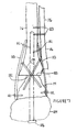
- FIG. 1 is a plan view of the fusion cutting block in accordance with an embodiment of the present invention mounted in an alignment jig shown in position on a patient;
- FIG.2 is a perspective view of the ankle fusion cutting block of Figure 1;
FIG. 2A is a cross sectional view of FIG. 2 along the
line 2A-LA in the directions of the arrows; - FIG.3 is a plan view of a cutting instrument for use with the ankle fusion cutting block of Figure 1;
- FIG. 4 is a front plan view of the ankle fusion cutting block of Figure 1;
- FIG.5 is a rear plan view of the ankle fusion cutting block of Figure 1;
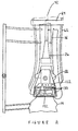
- FIG.6 is an end view of the fusion cutting block of Figure 1 mounted in an alignment jig shown in position on a patient;
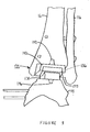
- FIG.7 is a partial medial lateral view of a patient showing a fused ankle joint;
- FIG. 8 is an end view of a total ankle arthroplasty cutting block mounted in the alignment jig of Figure 1 shown in position on a patient;
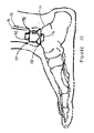
- FIG.9 is a partial plan view of a patient having a total ankle implant;
- FIG. 10 is a partial end view of a patient having a total ankle implant;
- FIG. 11 is a process flow chart for a first method of performing ankle fusion surgery according to a further embodiment of the present invention; and
- FIG.12 is a process flow chart for another method of performing ankle surgery according to yet another embodiment of the present invention.
-
- Embodiments of the present invention and the advantages thereof are best understood by referring to the following descriptions and drawings, wherein like numerals are used for like and corresponding parts of the drawings.
- According to the present invention and referring to FIG. 1, a
kit 10 for removal ofbone 12 from atalus 14 andtibia 16 of apatient 20 is shown. Thekit 10 is utilized to perform an ankle fusion procedure. Thekit 10 includes aguide 22 for cooperation with at least one of thetibia 16 andtalus 14. Thekit 10 further includes aninstrument 24, which is constrainable, byguide 22 for removal of thebone 12. - Referring now to FIGS. 2, 4 & 5 the
guide 22 of thekit 10 is shown in greater detail. As shown in FIG. 2, theguide 22 may include abody 26. Thebody 26 may define afirst constraint 30 for guiding theinstrument 24 for performing the tibia resection. Thebody 26 may also define asecond constraint 32 for guiding theinstrument 24 for performing the talus resection. Theconstraints instrument 24. For example, if theinstrument 24 is in the form of a cutting blade, theconstraints
To provide for a proper fusion of the ankle, the first constraint orslot 30 and the second constraint orslot 32 are preferably parallel to each other and spaced from each other a distance G. The dimension of the distance G may be slightly larger than the amount the ankle is distracted during the resection. The ankle may be distracted, for example, a distance of approximately one centimeter. The dimension G, thus, may be, for example, approximately 0.1 to 2.5 centimeters. Thefirst slot 30 and thesecond slot 32 preferably have a width W1 and W2, respectively. The width is selected to permit theinstrument 24 to slidably fit within the first andsecond slots instrument 24 may have a width W3 slightly smaller than the widths W1 and W2 of theslots first slot 30 has a width TISW which is slightly larger than the width TIW of the resected portion of the tibia. Similarly thesecond constraint 32 has a width TASW which is slightly longer than the width TAW of the resected portion of thetalus 14. - Referring again to FIG. 2, the
guide 22 may include additional features to guide additional instruments and to provide for particular configuration in the resection. For example, referring to FIG.2, thefirst slot 30 may include afirst relief hole 34 on one end of thefirst slot 30 and asecond relief hole 36 opposed to thefirst relief hole 34. The relief holes 34 and 36 serve as bushings to guidesecond instrument 40 in the form of, for example, a drill to prepare arcuate corners in the tibia resections. The relief holes 34 and 36 also serve as a starting point for wire EDM (electronic discharge machining) equipment. - The relief holes 34 and 36 are used to drill a hole through
tibia 16 on the medial side of thetibia 16 withdrill 40. Referring to FIG. 7, thedrill 40 forms arcuate surface 38 between resected surface 100 oftibia 16 and distal medial protrusions 39 oftibia 16. The arcuate surface 38 serves to prevent stress risers in the comers of the resected tibial bone. Further, the relief holes 34 and 36 eliminate the need to run theinstrument 24 all the way into the comer of the resectedtibia 16. - The
first starting hole drill 40. It should be appreciated that theslots second slot 32 does not include a relief hole but merely, as shown in FIG. 2, includes a smaller hole used in manufacturing to assist in the manufacture of theguide 22 by providing a starting point for wire EDM (electronic discharging machining) equipment. - The
guide 22 may be made of any suitable durable material capable of constraining theinstrument 24. For example, theguide 22 may be made of a metal or ceramic. For example, theguide 22 may be made of a titanium or cobalt chrome alloy or stainless steel. Preferably, theguide 22 is made of a material that is compatible with the human body. - Referring again to FIG. 1, the
guide 22, according to the present invention, may be positioned adjacent to thetibia 16 andtalus 14 by any suitable method. For example, theguide 22 may be fixably secured to ajig 42. It should be appreciated that theguide 22 may be indirectly secured to thetibia 16 or thetalus 14 or secured in any other indirect or direct manner. Preferably, however, to assure accurate andsecure positioning guide 22 during the resection of thetalus 14 andtibia 16, as shown in FIG.2, theguide 22 may further include mountingholes 44. The mounting holes 44 are for use as bushings for a cutting tool in the form of, for example, thedrill 40. Thedrill 40 is utilized to prepare mounting holes in thetibia 16. Theholes 44 and the mountingholes 46 in the tibia are connected utilizing a connector in the form, for example, pins 50. - Referring now to FIG. 2A, the
holes 44 are in the form of two parallel spaced-apartinner holes 52 as well as twoouter holes 54. As shown in FIG. 2A, the outer holes are oriented at an angle α toward each other. The angle α may be, for example, around 15 degrees. The angling of the outer holes serve to wedge theguide 22 against thetibia 16. As shown in FIG. 2A, preferably, theguide 22 is positioned adjacent totibia 16 to optimized the accuracy of the resection of the tibias and talus. -
Instrument 24 may be, as shown in FIG. 1, in the form of a cutting blade. It should be appreciated the instrument may be in the form of, for example a cutting tool, an osteotome, or a saw. It should be appreciated that preferably the instrument is closely fitted to the constraint or slot in theguide 22. - Referring again to FIG. 1, the
jig 42 is shown in greater detail. Thejig 42 may include, for example a base orbody 26. Theguide 22 is connected to thebody 26. Thebody 26 may include the adjustable mountingsurface 56 for adjustably mounting theguide 22 to thebody 26. The adjustable mountingsurface 56 is utilized to properly position theslots tibia 16 and thetalus 14. - The
body 26, as shown in FIG. 1, may be supported, for example, by means of a mountingarm 60. The mountingarm 60 secures thebody 26 to, for example,leg 62 of the patient. Theclamp 64 on the mountingarm 62 may be adapted to secure the mountingarm 60 to theleg 62. - Referring now to FIG. 3, the
instrument 24 is shown in greater detail. Theinstrument 24 may be in the form of a blade and may have teeth 66 located on anend 70 of theinstrument 24. The teeth 66 may have any shape suitable for an oscillating blade and may be, for example, the teeth 66 may have teeth such as that of a standard blade from Synvasive Corporation. Theinstrument 24 may include a connectingend 72 having features for connecting, for example, anoscillating motor 76. Themotor 76 may be any standard oscillating motor. - Referring now to FIG. 6, the
jig 42 is shown in position onleg 62 of the patient. As shown in FIG. 6 during an operation performing the ankle fusion utilizing the guide of the present invention, an incision is made in the skin between thetibia 16 and thetalus 14. - As shown in FIG. 6, a
standard ankle distractor 80 is available, for example, commercially available from Orthofix International N.V., Huntersville, North Carolina, is used to distract the ankle joint. The ankle distractor is, for example, secured to the patient bytibia pins 82 which are placed in thetibia 16 and talus distraction pins 84 which are placed in the patient'stalus 14 andcalcaneus 104. Theankle distractor 80 is actuated to separate thetibia 16 from the talus 14 a distance of, for example, one centimeter. - As shown in FIG. 6, the
body 26 of thejig 42 may include arough adjustment mechanism 86 which permits theguide 22 to the raised and lowered vertically to roughly position theguide 22 in a location between thetibia 16 and thetalus 14. - As shown in FIG. 6, the
jig 42 may also include a finetuning adjustment mechanism 90 which provides for precise adjustment of theguide 22 so that it may be precisely positioned between thetibia 16 andtalus 14. - Preferably, as shown in FIG.6, the
guide 22 may further include aposterior face 92 which preferably is positioned adjacent the interior face 94 of thetibia 16 and adjacent the interior face 96 of thetalus 14. - When the
guide 22 is properly positioned relative to thetibia 14 and thetalus 16, pins 50 are positioned in theholes 44 of theguide 22 to securely hold theguide 22 in position for the resection. - Referring now to FIG. 7, a fused ankle joint is shown utilizing the guide block of the present invention. As shown in FIG. 7, the resected surface 100 of the
talus 14 is placed against resectedsurface 102 of thetibia 16. - Preferably, as shown in FIG. 7, only a minimal amount of bone is removed from the
talus 14 and thetibia 16 such as that when the resected surface of 102 are fused together, the leg length of the patient will only be slightly shortened. In such a procedure where the leg length is only slightly shortened (for example, less than one centimeter, the difference in leg length will not be noticed by the patient. - If, due to damage to the
talus 14 and/or thetibia 16, it is necessary to remove more material from thetalus 14 and thetibia 16, either a bone graft (not shown) may be positioned between thetalus 14 and thetibia 16 or a lift or a corrective shoe (not shown) may need to be utilized by the patient to compensate for the difference in the patient's leg length. - Typically, during the ankle fusion, at least the
tibia 16 and thetalus 14 as well ascalcancus 104 are all fused together. The fusing of thetalus 14,tibia 16, andcalcancus 104 may be accomplished by one of several techniques. For example, anintermedullary rod 106 may be utilized to secure thecalcancus 104,talus 14 andtibia 16. Alternatively, the tibia, and talus can be fused together utilizing a combination ofbone plates 110 secured to the bones with bone plate screws 112, as well as by using the bone screws 114 to connect the talus to the tibia. During the anklefusion procedure fibula 116 may, for example, be resected and secured bybone screws 120 to thetibia 16. - From the examination of a patient, including the reading of x-rays, an orthopedic surgeon may determine that a patient is a candidate for a total ankle arthoplasty. Unfortunately, when the patient is brought into the surgery room and an incision is made into the patient around the ankle joint to initiate the total ankle arthoplasty, it may be discovered that due to the condition of the patient's tibia, talus, or adjacent soft tissue, a total ankle arthoplasty is not well advised and an ankle fusion may be the preferred procedure for the patient.
- Thus, according to the present invention and referring to FIG.8, the
jig 42 may be utilized for either a total ankle arthoplasty or an ankle fusion. For a patient in which the total ankle arthoplasty is planned, thejig 42 may be utilized to support asecond guide 122 which is used to prepare thetalus 14 and thetibia 16 for the resection cuts necessary to implant a total ankle implant. Thesecond guide 122 is similar to thefirst guide 22 and may include tibia slots 130 for performing the cuts on the tibia, as well astalus slot 132 for performing the resection of thetalus 14. Thesecond guide 122 may be secured, for example, to adjustable mountingsurface 56. Thesecond guide 122 may be made of any suitable durable material, for example, a metal, or steel. - As shown in FIG. 8 the
jig 42 including thesecond guide 22 is mounted withclamp 64 aroundleg 62 of the patient. An insection is made in the patient and thetibia 16 andtalus 14, as well as the adjacent soft tissue, is examined to determine whether or not a total ankle arthoplasty is advised for the patient. If the patient is a suitable candidate for the total ankle arthroplasty, thesecond guide 122 is mounted onto thejig 42. Conversely, if a total ankle arthoplasty is not well advised for the patient, and an ankle fusion is more suitable for the patient, theguide 22 is utilized and positioned in thejig 42. - Referring now to FIGS. 9 and 10, a total ankle joint prosthesis or
ankle implant 134 is shown implanted into thetibia 16,fibula 116 andtalus 14. As shown in FIGS. 9 and 10, theankle implant 134 is implanted withtalar member 138 attaching to thetalus 14 andtibia member 136 attaching to thetibia 16 andfibula 116 withbase plate 140 bridging the bones.Tibia strut 142 extends up into thetibia 16 when implanted and also positions thetibia member 136 correctly. Bearing 144, typically made of polyethylene, is positioned betweentibial member 136 and atalar member 138. - In a similar manner,
talar strut 146 extends down into thetalus 14 to keep thetalar member 138 properly aligned when implanted. Theankle implant 134 is preferably attached without cement as the surfaces of the ankle contacting the bones has a special coating, typically a porous coating to provide for bone in-growth, applied using a surface treatment, for example, microbeads of metal sintered onto the surface. - Since patients have different ankle sizes, different
size ankle implants 134 may be required. The correct size is obtained by comparing x-rays of each patient's ankles to an outline of each size implant. It has been found that small, medium, and large size implants provide sufficient variations to accommodate virtually all replacement situations. - Referring now to FIG. 11,
method 200 for providing ankle fusion surgery is described. Themethod 200 includes a first step 202 of providing an instrument for removing bone from at least one of a talus and a tibia. Themethod 200 further includes asecond step 204 of providing a guide for guiding the instrument. - The
method 200 also includes athird step 206 of fixedly securing the guide to the tibia. Themethod 200 also includes a fourth step 210 of positioning the instrument in the guide. Themethod 200 also includes afifth step 212 of removing bone from at least one of the tibia and the talus. Themethod 200 also includes asixth step 214 of fusing the tibia to the talus. - Referring now to FIG. 12, a
method 300 for providing ankle surgery includes thefirst step 302 of analyzing the condition of the tibia and talus and adjacent soft tissue. Themethod 300 also includes asecond step 306 of providing an instrument for removing bone from at least one of the talus and the tibia. Themethod 300 also includes athird step 310 of providing a first guide for guiding the instrument of removal of bone for performing an ankle fusion procedure. - The
method 300 further includes afourth step 312 of providing a second guide for guiding the instrument for removal of bone for performing a total ankle arthoplasty procedure. Themethod 300 further includes afifth step 314 of fixedly securing one of the first guide and the second guide to the tibia depending on the condition of the tibia, the talus and the adjacent soft tissue. - The
method 300 further includes asixth step 316 of positioning the instrument in one of the first guide and the second guide depending on the condition of the tibia, the talus, and the adjacent soft tissue. Themethod 300 further includes anseventh step 320 of removing bone from at least one of the tibia and the talus. Themethod 300 also includes aeighth step 322 of performing one of an ankle fusion procedure and a total ankle arthoplasty procedure depending on the condition of the tibia, the talus, and adjacent soft tissue. - The ankle fusion guide, jig, the method of the present invention, provides for an ankle fusion procedure in which a clean even cutting surface for ankle fusions is provided. The use of the guide with its stabilization pins provides a more accurate cut to perform ankle fusion. The ankle fusion guide that is positioned adjacent to the tibia and fibula can provide a guide surface flush with the joint to provide very little room for the saw blade to toggle or misalign during the resection of the tibia and talus.
- The jig and method including the use of both a total ankle arthoplasty resection guide, as well as fusion resection guide, provides a surgeon with the comfort of using instruments that may easily perform an ankle fusion if it appears during surgery that total ankle replacement surgery is not feasible.
- Although the present invention and its advantages have been described in detail, it should be understood that various changes, substitutions, and alterations can be made therein without departing from present invention as defined by the appended claims.
Claims (10)
- A kit for removal of bone from a talus and a tibia of a patient for performing ankle fusion, said kit comprising:a guide for cooperation with at least one of the tibia and the talus; andan instrument constrainable by said guide for removal of the bone.
- The kit of claim 1, wherein said guide comprises a body defining a first constraint for guiding said instrument for performing the tibia resection and defining a second constraint for guiding said instrument for performing the talus resection.
- The kit of claim 2, wherein at least one of the first constraint and the second constraint is defined by an opening in the body.
- The kit of claim 3, wherein the opening is a slot.
- The kit of claim 1, wherein said guide further defines a hole therethrough.
- The kit of claim 1, wherein said instrument comprises one of a burr tool, an osteotome, a saw and a cutting blade.
- The kit of claim 1, further comprising a jig for fixedly positioning said guide relative to the tibia and the talus.
- The kit of claim 7, further comprising a second guide for use in total ankle arthroplasty, said first mentioned guide and said second mentioned guide being removably fixedly postionable to said jig.
- The kit of claim 1, wherein said guide defines a first through slot, a second through slot spaced from and parallel to the first slot, and a plurality of circular though holes.
- A guide for guiding an instrument for the removal of bone from a first bone and a second bone of a patient for performing joint fusion therebetween, said guide comprising:a body; anda feature operably associated with said body for constraining the instrument.
Applications Claiming Priority (2)
| Application Number | Priority Date | Filing Date | Title |
|---|---|---|---|
| US226770 | 2002-08-26 | ||
| US10/226,770 US20040039394A1 (en) | 2002-08-26 | 2002-08-26 | Ankle fusion guide and method |
Publications (1)
| Publication Number | Publication Date |
|---|---|
| EP1393696A1 true EP1393696A1 (en) | 2004-03-03 |
Family
ID=31495319
Family Applications (1)
| Application Number | Title | Priority Date | Filing Date |
|---|---|---|---|
| EP03255220A Withdrawn EP1393696A1 (en) | 2002-08-26 | 2003-08-22 | Ankle fusion guide and method |
Country Status (4)
| Country | Link |
|---|---|
| US (1) | US20040039394A1 (en) |
| EP (1) | EP1393696A1 (en) |
| JP (1) | JP2004130109A (en) |
| AU (1) | AU2003235085A1 (en) |
Cited By (7)
| Publication number | Priority date | Publication date | Assignee | Title |
|---|---|---|---|---|
| WO2006120355A1 (en) * | 2005-05-13 | 2006-11-16 | Newdeal | Joint fusion apparatus for the ankle-type joint and arthrodetic pin for use in said apparatus |
| WO2008078082A3 (en) * | 2006-12-23 | 2009-03-12 | Corin Ltd | Improvements in and relating to an ankle prosthesis |
| RU2373882C1 (en) * | 2008-07-01 | 2009-11-27 | Общество с ограниченной ответственностью "ОСТЕОМЕД-М" (ООО "ОСТЕОМЕД-М") | Sprig for ankle joint arthrodesis |
| EP2099372A4 (en) * | 2006-12-15 | 2009-12-23 | Synthes Gmbh | Osteotomy guide and method of cutting the medial distal tibia employing the same |
| WO2011151657A1 (en) * | 2010-06-03 | 2011-12-08 | Biomet Uk Healthcare Limited | Guiding tool |
| WO2013169475A1 (en) * | 2012-05-08 | 2013-11-14 | Neal David J | Porous spacers, instruments, and methods for foot and ankle fusion |
| WO2023047330A1 (en) * | 2021-09-22 | 2023-03-30 | Crossroads Extremity Systems, Llc | Systems and methods for bone fixation |
Families Citing this family (98)
| Publication number | Priority date | Publication date | Assignee | Title |
|---|---|---|---|---|
| CA2495110C (en) * | 2002-08-10 | 2008-11-18 | H. Simon William | Method and apparatus for repairing the mid-foot region via an intramedullary nail |
| WO2005037135A2 (en) * | 2003-10-14 | 2005-04-28 | The University Of Iowa Research Foundation | Ankle prosthesis and method for implanting ankle prosthesis |
| GB0426002D0 (en) * | 2004-11-26 | 2004-12-29 | Depuy Int Ltd | A burr guide assembly |
| CA2601090C (en) * | 2005-03-14 | 2013-08-20 | Inbone Technologies, Inc. | Ankle replacement system |
| US20070233137A1 (en) * | 2006-02-15 | 2007-10-04 | Jai-Gon Seo | Tibia cutter |
| JP2009531078A (en) * | 2006-03-02 | 2009-09-03 | タラス メディカル, インコーポレイテッド | Artificial bone |
| US20110184413A1 (en) * | 2006-05-17 | 2011-07-28 | Gordon Slater | Ankle Fusion Plate |
| WO2009015009A1 (en) * | 2007-07-20 | 2009-01-29 | Talus Medical, Inc. | Methods and devices for deploying biological implants |
| EP2957243A1 (en) | 2007-09-30 | 2015-12-23 | DePuy Products, Inc. | Customized patient-specific orthopaedic surgical instrumentation |
| DE102008039241A1 (en) * | 2007-11-10 | 2009-05-14 | Waldemar Link Gmbh & Co. Kg | Instrumentarium for performing a surgical procedure on a joint |
| US20090248084A1 (en) * | 2008-03-27 | 2009-10-01 | Beat Hintermann | Systems and methods for performing ankle arthrodesis in a human patient |
| WO2011008739A2 (en) * | 2009-07-14 | 2011-01-20 | Medicinelodge, Inc. Dba Imds Co-Innovation | Joint arthrodesis and arthroplasty |
| CA2783553C (en) | 2009-12-11 | 2017-10-17 | Small Bone Innovations, Inc. | Ankle fusion device, instrumentation and methods |
| KR20140018185A (en) * | 2010-10-06 | 2014-02-12 | 세람테크 게엠베하 | Ceramic cutting template |
| US9161796B2 (en) | 2010-12-18 | 2015-10-20 | The Brigham And Women's Hospital, Inc. | Medical devices for use during ankle fusion surgery |
| US9186154B2 (en) | 2011-03-17 | 2015-11-17 | Zimmer, Inc. | Patient-specific instruments for total ankle arthroplasty |
| US10080573B2 (en) * | 2012-12-27 | 2018-09-25 | Wright Medical Technology, Inc. | Ankle replacement system and method |
| US9918724B2 (en) | 2012-12-27 | 2018-03-20 | Wright Medical Technology, Inc. | Ankle replacement system and method |
| CA2836651C (en) | 2012-12-27 | 2016-03-22 | Wright Medical Technology, Inc. | Ankle replacement system and method |
| US9974588B2 (en) | 2012-12-27 | 2018-05-22 | Wright Medical Technology, Inc. | Ankle replacement system and method |
| US9480571B2 (en) | 2012-12-27 | 2016-11-01 | Wright Medical Technology, Inc. | Ankle replacement system and method |
| CA2904652C (en) | 2013-03-14 | 2021-11-02 | Wright Medical Technology, Inc. | Ankle replacement system and method |
| US10610368B2 (en) | 2018-05-26 | 2020-04-07 | Acumed Llc | Ankle fusion system with expandable spacer |
| US9808288B2 (en) | 2014-05-02 | 2017-11-07 | Wright Medical Technology, Inc. | Circular fixator system and method |
| GB2528101A (en) * | 2014-07-10 | 2016-01-13 | Ortho Solutions Ltd | Apparatus for surgically replacing a human ankle joint |
| US20160015426A1 (en) | 2014-07-15 | 2016-01-21 | Treace Medical Concepts, Inc. | Bone positioning and cutting system and method |
| CN105555212B (en) * | 2014-08-26 | 2018-11-27 | 瑞特医疗技术公司 | Marrow inner support member with porous metals key |
| US9687250B2 (en) | 2015-01-07 | 2017-06-27 | Treace Medical Concepts, Inc. | Bone cutting guide systems and methods |
| US10849631B2 (en) | 2015-02-18 | 2020-12-01 | Treace Medical Concepts, Inc. | Pivotable bone cutting guide useful for bone realignment and compression techniques |
| US10653467B2 (en) | 2015-05-06 | 2020-05-19 | Treace Medical Concepts, Inc. | Intra-osseous plate system and method |
| WO2016201078A2 (en) | 2015-06-09 | 2016-12-15 | Mohamed Mahfouz | Patient-specific instrumentation and methods for total ankle replacement |
| US9622805B2 (en) | 2015-08-14 | 2017-04-18 | Treace Medical Concepts, Inc. | Bone positioning and preparing guide systems and methods |
| US10849663B2 (en) | 2015-07-14 | 2020-12-01 | Treace Medical Concepts, Inc. | Bone cutting guide systems and methods |
| CA3281165A1 (en) | 2015-07-14 | 2025-10-31 | Treace Medical Concepts, Inc. | Bone positioning guide |
| EP3334356B1 (en) | 2015-08-14 | 2024-10-02 | Treace Medical Concepts, Inc. | Fulcrum to be used during a procedure on the tarsal-metatarsal joint |
| EP4494582A3 (en) | 2015-08-14 | 2025-04-16 | Treace Medical Concepts, Inc. | Tarsal-metatarsal joint procedure utilizing fulcrum |
| EP4740879A2 (en) | 2015-09-18 | 2026-05-13 | Treace Medical Concepts, Inc. | Joint spacer systems |
| US20170172623A1 (en) * | 2015-12-18 | 2017-06-22 | Olympus Corporation | Method for ankle arthrodesis |
| US10258349B2 (en) * | 2015-12-18 | 2019-04-16 | Olympus Corporation | Arthroscopic surgery method for ankle impingement |
| EP3432838B1 (en) | 2016-03-23 | 2024-04-17 | Wright Medical Technology, Inc. | Fixation apparatus for total ankle replacement |
| US10512470B1 (en) | 2016-08-26 | 2019-12-24 | Treace Medical Concepts, Inc. | Osteotomy procedure for correcting bone misalignment |
| US10524808B1 (en) | 2016-11-11 | 2020-01-07 | Treace Medical Concepts, Inc. | Devices and techniques for performing an osteotomy procedure on a first metatarsal to correct a bone misalignment |
| USD865168S1 (en) * | 2016-12-21 | 2019-10-29 | Orthocape (Pty) Ltd | Plantar plate repair device |
| US10939939B1 (en) | 2017-02-26 | 2021-03-09 | Treace Medical Concepts, Inc. | Fulcrum for tarsal-metatarsal joint procedure |
| TWI786139B (en) | 2018-06-22 | 2022-12-11 | 財團法人工業技術研究院 | Artificial joint |
| US11051829B2 (en) | 2018-06-26 | 2021-07-06 | DePuy Synthes Products, Inc. | Customized patient-specific orthopaedic surgical instrument |
| AU2019302676B2 (en) | 2018-07-11 | 2025-03-06 | Treace Medical Concepts, Inc. | Compressor-distractor for angularly realigning bone portions |
| WO2020014660A1 (en) | 2018-07-12 | 2020-01-16 | Treace Medical Concepts, Inc. | Multi-diameter bone pin for installing and aligning bone fixation plate while minimizing bone damage |
| US11653938B2 (en) * | 2018-09-14 | 2023-05-23 | Drexel University | Patient-specific template for total ankle replacement |
| CN109171848B (en) * | 2018-09-27 | 2021-04-13 | 凌鸣 | Anterior ankle fusion measurement osteotomy |
| CA3122564A1 (en) * | 2018-12-13 | 2020-06-18 | Paragon 28, Inc. | Resection guides, sweeping reamers, and methods for use in total ankle replacement |
| AU2019395281B2 (en) | 2018-12-13 | 2025-07-24 | Paragon 28, Inc. | Joint replacement alignment guides, systems and methods of use and assembly |
| WO2020123899A1 (en) | 2018-12-13 | 2020-06-18 | Paragon 28, Inc. | Alignment instruments and methods for use in total ankle replacement |
| EP3893765A4 (en) | 2018-12-13 | 2023-03-29 | Paragon 28, Inc. | SURGICAL PROCEDURE FOR TOTAL ANKLE ATHROPLASTY |
| EP3893766B1 (en) | 2018-12-13 | 2025-09-03 | Paragon 28, Inc. | Systems for total ankle replacement |
| CA3122698A1 (en) | 2018-12-13 | 2020-06-18 | Paragon 28, Inc. | Distractors having attachable paddles, impaction devices, and methods for use in total ankle replacement |
| US11607250B2 (en) | 2019-02-13 | 2023-03-21 | Treace Medical Concepts, Inc. | Tarsal-metatarsal joint procedure utilizing compressor-distractor and instrument providing sliding surface |
| CN112168278A (en) * | 2019-07-03 | 2021-01-05 | 上海昕健医疗技术有限公司 | Surgical guide plate assembly for supra-ankle osteotomy and method of using the same |
| CA3146564A1 (en) | 2019-08-07 | 2021-02-11 | Jason May | Bi-planar instrument for bone cutting and joint realignment procedure |
| US11889998B1 (en) | 2019-09-12 | 2024-02-06 | Treace Medical Concepts, Inc. | Surgical pin positioning lock |
| US11986251B2 (en) | 2019-09-13 | 2024-05-21 | Treace Medical Concepts, Inc. | Patient-specific osteotomy instrumentation |
| US12490992B2 (en) | 2019-09-13 | 2025-12-09 | Treace Medical Concepts, Inc. | Patient-specific surgical methods and instrumentation |
| WO2021051098A1 (en) | 2019-09-13 | 2021-03-18 | Inmotus Medical Llc | Patient-specific surgical methods and instrumentation |
| US11890039B1 (en) | 2019-09-13 | 2024-02-06 | Treace Medical Concepts, Inc. | Multi-diameter K-wire for orthopedic applications |
| CN111053604A (en) * | 2020-01-03 | 2020-04-24 | 广西西斯达生物科技有限公司 | Digital automatic device for tibia transverse bone moving technology treatment |
| AU2021212261A1 (en) | 2020-01-31 | 2022-08-18 | Treace Medical Concepts, Inc. | Metatarsophalangeal joint preparation and metatarsal realignment for fusion |
| US12396737B2 (en) | 2020-04-16 | 2025-08-26 | Wright Medical Technology, Inc. | Chamfer guidance systems and methods |
| JP7769637B2 (en) | 2020-05-19 | 2025-11-13 | トリース メディカル コンセプツ,インコーポレイティド | Devices and techniques for treating metatarsal adduction |
| JP6989668B1 (en) * | 2020-08-24 | 2022-01-05 | HOYA Technosurgical株式会社 | Bone cutting guide |
| WO2022094502A1 (en) | 2020-10-28 | 2022-05-05 | Wright Medical Technology, Inc. | Talar implant |
| EP4185218A4 (en) | 2020-11-02 | 2024-10-30 | Wright Medical Technology, Inc. | MODULAR GUIDE ELEMENT SYSTEM FOR SURGICAL INTERVENTIONS |
| JP7759952B2 (en) | 2021-01-18 | 2025-10-24 | トリース メディカル コンセプツ,インコーポレイティド | Contoured bone plate with locking screws for bone compression, particularly across the tarsometatarsal joint |
| US12458365B2 (en) | 2021-02-05 | 2025-11-04 | Wright Medical Technology, Inc. | Surgical guide with cutting depth information |
| US12310603B2 (en) | 2021-02-18 | 2025-05-27 | Treace Medical Concepts, Inc. | System and technique for metatarsal realignment with reduced incision length |
| US12114872B2 (en) | 2021-03-30 | 2024-10-15 | Wright Medical Technology, Inc. | Alignment guide, systems, and methods |
| WO2022217223A1 (en) * | 2021-04-05 | 2022-10-13 | Paragon 28, Inc, | Instrumentation and methods for total ankle arthroplasty |
| WO2022246282A1 (en) | 2021-05-20 | 2022-11-24 | Treace Medical Concepts, Inc. | Cut guide with integrated joint realignment features |
| US12239539B2 (en) | 2021-06-07 | 2025-03-04 | Wright Medical Technology, Inc. | Joint replacement prosthesis with trans-cortical stems |
| US12350160B2 (en) | 2021-06-08 | 2025-07-08 | Wright Medical Technology, Inc. | Modular implant with external fixation |
| US12196856B2 (en) | 2021-06-09 | 2025-01-14 | Wright Medical Technology | Alignment systems and methods |
| US11872137B2 (en) | 2021-06-15 | 2024-01-16 | Wright Medical Technology, Inc. | Unicompartmental ankle prosthesis |
| US12465377B2 (en) | 2021-06-16 | 2025-11-11 | Wright Medical Technology, Inc. | Talar implant |
| US12201538B2 (en) | 2021-09-21 | 2025-01-21 | Wright Medical Technology, Inc. | Expanding tibial stem |
| US12396755B2 (en) | 2022-01-28 | 2025-08-26 | Wright Medical Technology, Inc. | Methods and apparatus for joint repair |
| USD1101146S1 (en) | 2022-02-23 | 2025-11-04 | Treace Medical Concepts, Inc. | Multi-sided cutting instrument for mobilizing small bones in the foot |
| USD1079011S1 (en) | 2022-02-23 | 2025-06-10 | Treace Medical Concepts, Inc. | Metatarsal cut guide with parallel cut faces |
| US12599389B2 (en) | 2022-02-23 | 2026-04-14 | Treace Medical Concepts, Inc. | Multi-sided cutting instrument for mobilizing small bones in the foot |
| USD1057155S1 (en) | 2022-02-23 | 2025-01-07 | Treace Medical Concepts, Inc. | Lesser metatarsal cut guide with parallel cut faces |
| CA3244723A1 (en) | 2022-02-23 | 2023-08-31 | Treace Medical Concepts, Inc. | First metatarsal lateral release instrument and technique |
| USD1051382S1 (en) | 2022-02-23 | 2024-11-12 | Treace Medical Concepts, Inc. | Lesser metatarsal cut guide |
| USD1075012S1 (en) | 2022-02-23 | 2025-05-13 | Treace Medical Concepts, Inc. | Metatarsal lateral release instrument |
| USD1011524S1 (en) | 2022-02-23 | 2024-01-16 | Treace Medical Concepts, Inc. | Compressor-distractor for the foot |
| US12478381B2 (en) | 2022-02-24 | 2025-11-25 | Treace Medical Concepts, Inc | Devices and techniques for treating lesser metatarsals of the foot |
| US12605172B2 (en) | 2022-04-27 | 2026-04-21 | Wright Medical Technology, Inc. | Methods and system for extramedullary guidance |
| US12433532B2 (en) | 2022-06-02 | 2025-10-07 | Wright Medical Technology, Inc. | Flexion/extension surgical guides and methods of using the same |
| USD1068078S1 (en) | 2023-02-08 | 2025-03-25 | Treace Medical Concepts, Inc. | Handle for an orthopedic instrument |
| USD1068077S1 (en) | 2023-02-08 | 2025-03-25 | Treace Medical Concepts, Inc. | Orthopedic rasp for preparing an intercuneiform joint |
| CN120420135B (en) * | 2025-04-21 | 2025-10-17 | 北京力达康科技有限公司 | An implant for ankle replacement surgery |
Citations (3)
| Publication number | Priority date | Publication date | Assignee | Title |
|---|---|---|---|---|
| US4524766A (en) * | 1982-01-07 | 1985-06-25 | Petersen Thomas D | Surgical knee alignment method and system |
| FR2715557A1 (en) * | 1994-01-28 | 1995-08-04 | Lepine Groupe | Three part prosthetic ankle joint |
| FR2759900A1 (en) * | 1997-02-26 | 1998-08-28 | Sem Sa | Ancillary instrument for fitting components of ankle joint prosthesis |
Family Cites Families (15)
| Publication number | Priority date | Publication date | Assignee | Title |
|---|---|---|---|---|
| US4470158A (en) * | 1978-03-10 | 1984-09-11 | Biomedical Engineering Corp. | Joint endoprosthesis |
| US4554915A (en) * | 1983-03-08 | 1985-11-26 | Richards Medical Company | Bone fixation frame |
| US4718413A (en) * | 1986-12-24 | 1988-01-12 | Orthomet, Inc. | Bone cutting guide and methods for using same |
| US4968316A (en) * | 1988-12-12 | 1990-11-06 | Hergenroeder Patrick T | Arthroscopic ankle joint distraction method |
| US5234433A (en) * | 1989-09-26 | 1993-08-10 | Kirschner Medical Corporation | Method and instrumentation for unicompartmental total knee arthroplasty |
| EP0630212B1 (en) * | 1992-02-20 | 1998-07-08 | Synvasive Technology, Inc. | Surgical cutting block |
| US5326365A (en) * | 1992-04-10 | 1994-07-05 | Alvine Franklin G | Ankle implant |
| US5569260A (en) * | 1994-12-01 | 1996-10-29 | Petersen; Thomas D. | Distal femoral resector guide |
| US5766259A (en) * | 1995-03-14 | 1998-06-16 | Sammarco; Giacomo J. | Total ankle prosthesis and method |
| US5830216A (en) * | 1996-10-30 | 1998-11-03 | Bristol-Myers Squibb Company | Apparatus and method for knee implantation |
| US6090114A (en) * | 1997-02-10 | 2000-07-18 | Stryker Howmedica Osteonics Corp. | Tibial plateau resection guide |
| US6478799B1 (en) * | 2000-06-29 | 2002-11-12 | Richard V. Williamson | Instruments and methods for use in performing knee surgery |
| US6558391B2 (en) * | 2000-12-23 | 2003-05-06 | Stryker Technologies Corporation | Methods and tools for femoral resection in primary knee surgery |
| US6875222B2 (en) * | 2002-03-12 | 2005-04-05 | Depuy Products, Inc. | Blade for resection of bone for prosthesis implantation, blade stop and method |
| US7993341B2 (en) * | 2004-03-08 | 2011-08-09 | Zimmer Technology, Inc. | Navigated orthopaedic guide and method |
-
2002
- 2002-08-26 US US10/226,770 patent/US20040039394A1/en not_active Abandoned
-
2003
- 2003-08-19 AU AU2003235085A patent/AU2003235085A1/en not_active Abandoned
- 2003-08-22 EP EP03255220A patent/EP1393696A1/en not_active Withdrawn
- 2003-08-25 JP JP2003300149A patent/JP2004130109A/en active Pending
Patent Citations (3)
| Publication number | Priority date | Publication date | Assignee | Title |
|---|---|---|---|---|
| US4524766A (en) * | 1982-01-07 | 1985-06-25 | Petersen Thomas D | Surgical knee alignment method and system |
| FR2715557A1 (en) * | 1994-01-28 | 1995-08-04 | Lepine Groupe | Three part prosthetic ankle joint |
| FR2759900A1 (en) * | 1997-02-26 | 1998-08-28 | Sem Sa | Ancillary instrument for fitting components of ankle joint prosthesis |
Cited By (14)
| Publication number | Priority date | Publication date | Assignee | Title |
|---|---|---|---|---|
| US8740902B2 (en) | 2005-05-13 | 2014-06-03 | Newdeal | Joint fusion apparatus for the ankle-type joint and arthrodetic pin for use in said apparatus |
| FR2885513A1 (en) * | 2005-05-13 | 2006-11-17 | Newdeal S A S Soc Par Actions | ARTHRODESIS APPARATUS FOR ARTICULATION, OF THE GENUS ARTICULATION OF THE ANKLE, AND NAIL OF ATHRODESE FOR USE IN SUCH AN APPARATUS |
| WO2006120355A1 (en) * | 2005-05-13 | 2006-11-16 | Newdeal | Joint fusion apparatus for the ankle-type joint and arthrodetic pin for use in said apparatus |
| EP2099372A4 (en) * | 2006-12-15 | 2009-12-23 | Synthes Gmbh | Osteotomy guide and method of cutting the medial distal tibia employing the same |
| WO2008078082A3 (en) * | 2006-12-23 | 2009-03-12 | Corin Ltd | Improvements in and relating to an ankle prosthesis |
| RU2373882C1 (en) * | 2008-07-01 | 2009-11-27 | Общество с ограниченной ответственностью "ОСТЕОМЕД-М" (ООО "ОСТЕОМЕД-М") | Sprig for ankle joint arthrodesis |
| US9445823B2 (en) | 2010-06-03 | 2016-09-20 | Biomet Uk Healthcare Limited | Guiding tool |
| WO2011151657A1 (en) * | 2010-06-03 | 2011-12-08 | Biomet Uk Healthcare Limited | Guiding tool |
| WO2013169475A1 (en) * | 2012-05-08 | 2013-11-14 | Neal David J | Porous spacers, instruments, and methods for foot and ankle fusion |
| US9220518B2 (en) | 2012-05-08 | 2015-12-29 | Zimmer, Inc. | Porous spacers, instruments, and methods for foot and ankle fusion |
| US9492178B2 (en) | 2012-05-08 | 2016-11-15 | Zimmer, Inc. | Porous spacers, instruments, and methods for foot and ankle fusion |
| AU2013260048B2 (en) * | 2012-05-08 | 2017-07-06 | Zimmer, Inc. | Porous spacers, instruments, and methods for foot and ankle fusion |
| WO2023047330A1 (en) * | 2021-09-22 | 2023-03-30 | Crossroads Extremity Systems, Llc | Systems and methods for bone fixation |
| US12575839B2 (en) | 2021-09-22 | 2026-03-17 | Crossroads Extremity Systems, Llc | Systems and methods for bone fixation |
Also Published As
| Publication number | Publication date |
|---|---|
| JP2004130109A (en) | 2004-04-30 |
| AU2003235085A1 (en) | 2004-03-11 |
| US20040039394A1 (en) | 2004-02-26 |
Similar Documents
| Publication | Publication Date | Title |
|---|---|---|
| US20040039394A1 (en) | Ankle fusion guide and method | |
| US12156664B2 (en) | Resection guides, sweeping reamers, and methods for use in total ankle replacement | |
| US12303139B2 (en) | Alignment guides, cut guides, systems and methods of use and assembly | |
| US5702460A (en) | Revision femoral trial prosthesis | |
| EP0121142B1 (en) | Apparatus for shaping a distal femoral surface | |
| JP4567686B2 (en) | Ankle prosthesis and method for transplanting an ankle prosthesis | |
| US6916324B2 (en) | Provisional orthopedic prosthesis for partially resected bone | |
| AU696251B2 (en) | Distal femoral cutting guide | |
| CA2836651C (en) | Ankle replacement system and method | |
| US9480571B2 (en) | Ankle replacement system and method | |
| US8128630B2 (en) | Tibial augmentation guide | |
| JP4414209B2 (en) | Method and apparatus for achieving correct limb alignment during monoarticular knee arthroplasty | |
| US20040078043A1 (en) | Joint replacement methods and apparatus | |
| US20110276052A1 (en) | Method of Preparing an Ankle Joint for Replacement, Joint Prosthesis, and Cutting Alignment Apparatus for Use in Performing an Arthroplasty Procedure | |
| JPH11514906A (en) | Osteotomy guide for use when implanting prosthetic components | |
| JPH02239861A (en) | Shank surface shaping guide for knee implantation | |
| EP2849684A1 (en) | Porous spacers, instruments, and methods for foot and ankle fusion | |
| AU2019229415B2 (en) | Variable angle cutting guide and method of using the same | |
| EP1414356B1 (en) | Guide for locating femur resection plane | |
| US20040078042A1 (en) | Bone-conserving orthopedic instrumentation and appliances | |
| AU2015202080B2 (en) | Ankle replacement system and method |
Legal Events
| Date | Code | Title | Description |
|---|---|---|---|
| PUAI | Public reference made under article 153(3) epc to a published international application that has entered the european phase |
Free format text: ORIGINAL CODE: 0009012 |
|
| AK | Designated contracting states |
Kind code of ref document: A1 Designated state(s): AT BE BG CH CY CZ DE DK EE ES FI FR GB GR HU IE IT LI LU MC NL PT RO SE SI SK TR |
|
| AX | Request for extension of the european patent |
Extension state: AL LT LV MK |
|
| 17P | Request for examination filed |
Effective date: 20040730 |
|
| 17Q | First examination report despatched |
Effective date: 20040913 |
|
| AKX | Designation fees paid |
Designated state(s): AT BE BG CH CY CZ DE DK EE ES FI FR GB GR HU IE IT LI LU MC NL PT RO SE SI SK TR |
|
| STAA | Information on the status of an ep patent application or granted ep patent |
Free format text: STATUS: THE APPLICATION IS DEEMED TO BE WITHDRAWN |
|
| 18D | Application deemed to be withdrawn |
Effective date: 20050125 |