EP1392450B1 - Ausdrückvorrichtung für eine coaxialkartusche - Google Patents
Ausdrückvorrichtung für eine coaxialkartusche Download PDFInfo
- Publication number
- EP1392450B1 EP1392450B1 EP02791828A EP02791828A EP1392450B1 EP 1392450 B1 EP1392450 B1 EP 1392450B1 EP 02791828 A EP02791828 A EP 02791828A EP 02791828 A EP02791828 A EP 02791828A EP 1392450 B1 EP1392450 B1 EP 1392450B1
- Authority
- EP
- European Patent Office
- Prior art keywords
- expressing
- tube
- expressing device
- cutting
- internal
- Prior art date
- Legal status (The legal status is an assumption and is not a legal conclusion. Google has not performed a legal analysis and makes no representation as to the accuracy of the status listed.)
- Expired - Lifetime
Links
Images


Classifications
-
- B—PERFORMING OPERATIONS; TRANSPORTING
- B05—SPRAYING OR ATOMISING IN GENERAL; APPLYING FLUENT MATERIALS TO SURFACES, IN GENERAL
- B05C—APPARATUS FOR APPLYING FLUENT MATERIALS TO SURFACES, IN GENERAL
- B05C17/00—Hand tools or apparatus using hand held tools, for applying liquids or other fluent materials to, for spreading applied liquids or other fluent materials on, or for partially removing applied liquids or other fluent materials from, surfaces
- B05C17/005—Hand tools or apparatus using hand held tools, for applying liquids or other fluent materials to, for spreading applied liquids or other fluent materials on, or for partially removing applied liquids or other fluent materials from, surfaces for discharging material from a reservoir or container located in or on the hand tool through an outlet orifice by pressure without using surface contacting members like pads or brushes
- B05C17/01—Hand tools or apparatus using hand held tools, for applying liquids or other fluent materials to, for spreading applied liquids or other fluent materials on, or for partially removing applied liquids or other fluent materials from, surfaces for discharging material from a reservoir or container located in or on the hand tool through an outlet orifice by pressure without using surface contacting members like pads or brushes with manually mechanically or electrically actuated piston or the like
- B05C17/0106—Hand tools or apparatus using hand held tools, for applying liquids or other fluent materials to, for spreading applied liquids or other fluent materials on, or for partially removing applied liquids or other fluent materials from, surfaces for discharging material from a reservoir or container located in or on the hand tool through an outlet orifice by pressure without using surface contacting members like pads or brushes with manually mechanically or electrically actuated piston or the like with means for longitudinally cutting container walls during relative displacement of the piston and its cooperating container
-
- B—PERFORMING OPERATIONS; TRANSPORTING
- B05—SPRAYING OR ATOMISING IN GENERAL; APPLYING FLUENT MATERIALS TO SURFACES, IN GENERAL
- B05C—APPARATUS FOR APPLYING FLUENT MATERIALS TO SURFACES, IN GENERAL
- B05C17/00—Hand tools or apparatus using hand held tools, for applying liquids or other fluent materials to, for spreading applied liquids or other fluent materials on, or for partially removing applied liquids or other fluent materials from, surfaces
- B05C17/005—Hand tools or apparatus using hand held tools, for applying liquids or other fluent materials to, for spreading applied liquids or other fluent materials on, or for partially removing applied liquids or other fluent materials from, surfaces for discharging material from a reservoir or container located in or on the hand tool through an outlet orifice by pressure without using surface contacting members like pads or brushes
- B05C17/00553—Hand tools or apparatus using hand held tools, for applying liquids or other fluent materials to, for spreading applied liquids or other fluent materials on, or for partially removing applied liquids or other fluent materials from, surfaces for discharging material from a reservoir or container located in or on the hand tool through an outlet orifice by pressure without using surface contacting members like pads or brushes with means allowing the stock of material to consist of at least two different components
- B05C17/00559—Hand tools or apparatus using hand held tools, for applying liquids or other fluent materials to, for spreading applied liquids or other fluent materials on, or for partially removing applied liquids or other fluent materials from, surfaces for discharging material from a reservoir or container located in or on the hand tool through an outlet orifice by pressure without using surface contacting members like pads or brushes with means allowing the stock of material to consist of at least two different components the different components being stored in coaxial chambers
-
- B—PERFORMING OPERATIONS; TRANSPORTING
- B26—HAND CUTTING TOOLS; CUTTING; SEVERING
- B26D—CUTTING; DETAILS COMMON TO MACHINES FOR PERFORATING, PUNCHING, CUTTING-OUT, STAMPING-OUT OR SEVERING
- B26D3/00—Cutting work characterised by the nature of the cut made; Apparatus therefor
- B26D3/001—Cutting tubes longitudinally
-
- B—PERFORMING OPERATIONS; TRANSPORTING
- B05—SPRAYING OR ATOMISING IN GENERAL; APPLYING FLUENT MATERIALS TO SURFACES, IN GENERAL
- B05C—APPARATUS FOR APPLYING FLUENT MATERIALS TO SURFACES, IN GENERAL
- B05C17/00—Hand tools or apparatus using hand held tools, for applying liquids or other fluent materials to, for spreading applied liquids or other fluent materials on, or for partially removing applied liquids or other fluent materials from, surfaces
- B05C17/005—Hand tools or apparatus using hand held tools, for applying liquids or other fluent materials to, for spreading applied liquids or other fluent materials on, or for partially removing applied liquids or other fluent materials from, surfaces for discharging material from a reservoir or container located in or on the hand tool through an outlet orifice by pressure without using surface contacting members like pads or brushes
- B05C17/00576—Hand tools or apparatus using hand held tools, for applying liquids or other fluent materials to, for spreading applied liquids or other fluent materials on, or for partially removing applied liquids or other fluent materials from, surfaces for discharging material from a reservoir or container located in or on the hand tool through an outlet orifice by pressure without using surface contacting members like pads or brushes characterised by the construction of a piston as pressure exerting means, or of the co-operating container
-
- Y—GENERAL TAGGING OF NEW TECHNOLOGICAL DEVELOPMENTS; GENERAL TAGGING OF CROSS-SECTIONAL TECHNOLOGIES SPANNING OVER SEVERAL SECTIONS OF THE IPC; TECHNICAL SUBJECTS COVERED BY FORMER USPC CROSS-REFERENCE ART COLLECTIONS [XRACs] AND DIGESTS
- Y10—TECHNICAL SUBJECTS COVERED BY FORMER USPC
- Y10T—TECHNICAL SUBJECTS COVERED BY FORMER US CLASSIFICATION
- Y10T83/00—Cutting
- Y10T83/202—With product handling means
Definitions
- the invention relates to a Ausd Wegvortechnische for a coaxial cartridge after the The preamble of claim 1 and a coaxial cartridge with such Expressing device according to the preamble of claim 14.
- a coaxial cartridge of the type mentioned in the introduction is e.g. from FR-A-1470125.
- Such cartridges are often used for storage and Processing of reactive adhesives, sealants and the like. Used. They point usually an outer tube and a coaxial inner tube, which has an inner and outer Limit the receiving chamber for the different components.
- the standard commercial Dosierpistolen have namely only a ram that stand up on the inner tube and a squeezing would prevent.
- the inner tube of a coaxial cartridge as foldable Form aluminum tube, so that the inner tube when pressing the coaxial cartridge with a commercial metering gun for one-component cartridges is folded.
- this embodiment has the disadvantage that special requirements for the filling of Resins and to the assembly of the pistons must be put. Also with regard to the Disposal are not made of plastic and metal parts coaxial cartridges ideal.
- the object of the invention is to provide a squeezing device and a coaxial cartridge to create the aforementioned type, which increases the filling volume with commercial dispensing guns allow expressible coaxial cartridges.
- the inventive concept is that the inner tube of a coaxial cartridge during Express the coaxial cartridge separated by a separator and on the inner wall of the outer tube is bent. This is done by a special designed ejection device, which has a separator for separating the inner tube and a deflecting device for deflecting the at least one separated Pipe section to the inner wall of the outer tube contains.
- This expressing device can as be executed separate component or integrated into the sealing piston of the cartridge.
- the separator contains the Separator two cutting elements through which the inner tube in about two equal big halves is split.
- the separator may also only one or more than have two cutting elements for separating the inner tube.
- the cutting element expediently a plastic blade, the one-piece with the as Plastic injection molded part produced expressing device is executed.
- the cutting element But can also be injected as a single part plastic blade, in the Expressing device is mounted.
- Cutting blades are used in metal. Metal blades are preferred as Inserted parts integrated in the ejection device produced by injection molding.
- the cutting elements are advantageously mounted so that they the inner tube not at right angles to the pipe wall, but cut diagonally. This allows the Cutting resistance can be reduced.
- the cutting blades are under one Angle of 45-60 ° to a tangent to a fitting in the inner tube guide piece of Expressing device arranged.
- the deflection device expediently consists of conical deflecting surfaces and / or inclined guide surfaces through which the separated sections of the Inner tube directed to the side slits and o.ä at the ram of Dosierpistole. be led past. Due to the deflection and the side slots is the split inner tube wall bent and pressed against the inner wall of the outer tube.
- the inner part of the Expressing device widens from the matching in the inner tube front guide part preferably continuous until the rear end. As a result, the inner tube is under Tension set, whereby the cutting is facilitated.
- To prepare the Cutting blades for relief can be provided at the end of the inner tube e.g. V-shaped notches be provided.
- the squeezing device is preferably preassembled in the coaxial cartridge. This will be expediently the inner tube of the cartridge by the length of the ejection device shortened, so that the squeezing device is covered by the outer tube and the Expressing device when the cartridge starts to extrude through the outer tube to be led.
- one or more additional deflectors provided by the one end of the at least one separated portion of the Inner tube inwards and / or the other end is pressed outwards.
- the sections accumulate less in the region of the separation point on each other, causing the separation facilitates and the cutting resistance is reduced.
- FIG. 1 schematically shows a part of a two-component coaxial cartridge 1 with a Outer tube 2 and a concentric inner tube 3 shown.
- the inner tube 3 forms a inner chamber 4, in which a central inner piston 5 is slidably disposed.
- the inner chamber 4 and the outer annular chamber 6 serve to be distributed Material components by displacement of the two pistons 5 and 7 by means of a Preßstkovs 8 a commercial metering gun or the like.
- Exit cartridge outlet On a not shown Exit cartridge outlet.
- In the embodiment shown in Figure 1 is between the two pistons 5 and 7 and the ram 8 a closer in the following explained ejection device arranged.
- the Ausd Wegvorcardi shown in Figure 1 in a cross section is in the form of a Tappet with a cylindrical outer wall 9 and a conically widening Inner part 10 executed.
- the outer diameter of the outer wall 9 is slightly smaller than the inner diameter of the outer tube 2.
- the inner part 10 has at its piston side front end in the inner tube 3 matching central guide piece 11, which in the shown embodiment has an oval cross-section. From the leader 11 tapered deflecting surfaces 12 extend to two opposite outlet slots 13, in the region of the outer wall 9 at the press ram 8 facing the rear end of the Plunger are arranged.
- the inner part 10 is as a hollow part with a plurality of equiangularly spaced and executed in cross-section circular segment-shaped through holes 17.
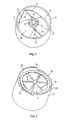
- FIG. 2 to 4 is another embodiment of a squeezing device shown.
- This embodiment differs from that shown in FIG 10 also includes a central tube fitting into the inner tube 3 of a coaxial cartridge 1 Guide piece 11, from the conical deflecting surfaces 12 to two opposite Exit slots 13 extend.
- Between the outer wall 9 and the inner part 10 are also here connecting webs with an upper edge 14 and sloping on both sides Guide surfaces 15 are provided.
- the upper edges 14 are here as cutting edges Embodiment only in that the cutting blades 16 is not on a through the Center of the guide member 11 extending common axis, but to each other parallel offset at an angle ⁇ of less than 90 °, preferably between 45 and 60 °, with respect to a tangent 19 to the guide part 11 are arranged.
- the back end facing the press ram has the Expressing device two arcuately extending centering webs 20 with inward tapered Zenrier vom 21 provided.
- centering webs 20 Through the between the exit slots 13 arranged centering webs 20 is a central arrangement of the press ram 8 at the Expressing device and a safe passage of the sections 18 on the ram reached.
- FIGS. 5 to 7 show a further embodiment of a squeezing device which for a 1: 1 two-component coaxial cartridges with the same capacity of the inner and outer chamber is determined.
- the diameter of the here with a circular cross-section executed guide piece 11 to the corresponding adapted larger inner diameter of the inner tube.
- the cutting blades 16 on the upper edge 14 of a connecting web between the inner guide member 11 and arranged on the outer wall 9 and separated by the cutting blades 16 sections be by conical deflecting surfaces 12 and curved or inclined guide surfaces 15 directed to the lateral outlet slots 13.
- the on the top bevelled cutting blades 16 diametrically opposite one another through arranged the center of the expressing device extending central axis 22.
- FIGS. 8 and 9 Another embodiment of a squeezing device is shown in FIGS. 8 and 9 shown. Also there, the ejection device has a cylindrical outer wall 9 and a in the direction of the ram tapered inner part 10 on. The inner part formed and form the separator for separating the inner tube 3 in two Sections 23 and 24. In this embodiment are on the outside of the guide piece eleventh below the edges 14 two diametrically opposite and on opposite sides the edges 14 arranged first deflector 25 in the form of outwardly projecting Protrusions molded. By this deflector 25 is the one end of the separated Gates 23 and 24 of the inner tube 3 in the region of the edge 14 is pressed radially outward.
- the first deflectors 23 opposite are on the other side of the edges 14 optional second deflectors 26 are provided, through which the inwardly bent ends opposite ends of the respective other wall portion 23 and 24 of the inner tube. 3 be pressed radially inward.
- In the guide piece 11 are diametrically opposite recesses 27 for receiving the inwardly pressed ends of the Sections 23 and 24 provided. The ends of the split portions 23 and 24 become so pressed apart in the area of the cutting edge and compress so less each other up. In this way, the cutting process is less hindered and the Cutting resistance reduced.
- the Ausdrückvorraumraumen described above are expediently as Injection molded parts produced.
- the cutting blades can be integral with the injection molding as Be executed plastic blades. But you can also firmly injected into the injection molded part or interchangeable cutting blades made of metal.
- the invention is not limited to those described above and illustrated in the drawings Embodiments limited.
- the expressing device by appropriate Dimensioning of the outer wall and the inner part for all standard coaxial cartridges with all filling volume ratios of the inner and outer chamber be used.
Description
- Figur 1
- eine Teilansicht einer Zweikomponenten-Coaxialkartusche mit Kolben, Preßstempel und einer erfindungsgemäßen Ausdrückvorrichtung im Schnitt;
- Figur 2
- eine Draufsicht auf den zum Kolben gewandten Teil einer zweiten Ausführungsform einer erfindungsgemäßen Ausdrückvorrichtung;
- Figur 3
- eine perspektivische Ansicht des zum Kolben gewandten Teils der in Figur 2 dargestellten Ausdrückvorrichtung;
- Figur 4
- eine perspektivische Ansicht des zum Preßstempel gewandten Teils der in Figur 2 dargestellten Ausdrückvorrichtung;
- Figur 5
- eine Draufsicht auf den zum Kolben gewandten Teil einer dritten Ausführungsform einer erfindungsgemäßen Ausdrückvorrichtung;
- Figur 6
- eine Schnittansicht entlang der Linie A-A von Figur 5 und
- Figur 7
- eine perspektivische Ansicht des zum Kolben gewandten Teils eines zweiten Ausführungsbeispiels einer Vorrichtung zum Auftrennen des Innenrohrs einer 1:1-Coaxialkartusche und
- Figur 8
- eine weitere Ausführungsform einer Ausdrückvorrichtung in einer Schnittansicht entlang der Linie A-A von Figur 9 und
- Figur 9
- eine Draufsicht auf den zum Kolben gewandten Teil der in Figur 8 gezeigten Ausführungsform einer Ausdrückvorrichtung.
Claims (19)
- Ausdrückvorrichtung für eine Coaxialkartusche mit einem Außenrohr (2) und einem Innenrohr (3), mit einer Trenneinrichtung (14, 16) zum Auftrennen eines Innenrohrs (3) gekennzeichnet durch eine Umlenkeinrichtung (12, 13, 15) zum Umlenken des mindestens einen aufgetrennten Abschnitts des Innenrohrs (3) zur Innenwand des Außenrohrs (2) beim Ausdrücken der Coaxialkartusche.
- Ausdrückvorrichtung nach Anspruch 1, dadurch gekennzeichnet, daß die Trenneinrichtung mindestens ein Schneidelement (16) zum Durchtrennen der Wandung des Innenrohrs (3) enthält.
- Ausdrückvorrichtung nach Anspruch 2, dadurch gekennzeichnet, daß das mindestens eine Schneidelement (16) eine integrierte oder einsetzbare Kunststoff- oder Metallklinge ist.
- Ausdrückvorrichtung nach Anspruch 2 oder 3, dadurch gekennzeichnet, daß das mindestens eine Schneidelement (16) senkrecht oder schräg zur Rohrwandung des Innenrohrs (3) angeordnet ist.
- Ausdrückvorrichtung nach einem der Ansprüche 2 bis 4, dadurch gekennzeichnet, daß das mindestens eine Schneidelement (16) neben einem in das Innenrohr (3) passenden Führungsstück (11) eines sich in Richtung mindestens eines seitlichen Austrittsschlitzes (13) erweiternden Innenteils (10) der Ausdrückvorrichtung angeordnet ist.
- Ausdrückvorrichtung nach Anspruch 5, dadurch gekennzeichnet, daß sich das Innenteil (10) in Richtung des mindestens einen Austrittsschlitzes (13) kontinuierlich oder stufenweise erweitert.
- Ausdrückvorrichtung nach einem der Ansprüche 2 bis 6, dadurch gekennzeichnet, daß das mindestens eine Schneidelement (16) auf einem Verbindungssteg (14, 15) zwischen einer zylindrischen Außenwand (9) und dem Innenteil (10) angeordnet ist.
- Ausdrückvorrichtung nach einem der Ansprüche 1 bis 7, dadurch gekennzeichnet, daß die Umlenkeinrichtung (12, 13, 15) kegelförmige Umlenkflächen (12) und/oder schräge Führungsflächen (15) zum Umlenken des mindestens einen aufgetrennten Abschnitts des Innenrohrs (3) zu einem oder mehreren seitlichen Schlitzen (13) aufweist.
- Ausdrückvorrichtung nach einem der Ansprüche 1 bis 8, dadurch gekennzeichnet, daß sie an ihrem zu einem Preßstempel (8) gewandten hinteren Ende Zentrierelemente (20) enthält.
- Ausdrückvorrichtung nach einem der Ansprüche 1 bis 9, dadurch gekennzeichnet, daß im Bereich der Trenneinrichtung (14, 16) ein oder mehrere zusätzliche Abweiser (25, 26) vorgesehen sind, durch die das eine Ende des mindestens einen aufgetrennten Abschnitts (23, 24) des Innenrohrs (3) nach innen und/oder das andere Ende nach außen gedrückt wird.
- Ausdrückvorrichtung nach Anspruch 10, dadurch gekennzeichnet, daß die zusätzlichen Abweiser (25, 26) aus einem ersten Abweiser (25) auf der einen Seite der Trennneinrichtung (14, 16) und einem zweiten Abweiser (26) auf der anderen Seite der Trenneinrichtung (14, 16) bestehen.
- Ausdrückvorrichtung nach einem der Ansprüche 5 bis 11, dadurch gekennzeichnet, daß das Führungsstück (11) mindestens eine Einbuchtung (27) zur Aufnahme des nach innen gedrückten Endes des mindestens einen aufgetrennten Abschnitts (23, 24) des Innenrohrs (3) aufweist.
- Ausdrückvorrichtung nach einem der Ansprüche 1 bis 12, dadurch gekennzeichnet, daß sie als einteiliges Spritzgußteil ausgeführt ist.
- Coaxialkartusche mit einem Außenrohr (2), einem Innenrohr (3) und einer Ausdrückvorrichtung, dadurch gekennzeichnet, daß die Ausdrückvorrichtung nach einem der Ansprüche 1 bis 13 ausgebildet ist.
- Coaxialkartusche nach Anspruch 14, dadurch gekennzeichnet, daß das Innenrohr (3) mindestens eine Kerbe zum Ansetzen der Trenneinrichtung (14, 16) enthält.
- Coaxialkartusche nach Anspruch 14 oder 15, dadurch gekennzeichnet, daß die Ausdrückvorrichtung als gesondertes Teil ausgeführt ist.
- Coaxialkartusche nach Anspruch 14 oder 15, dadurch gekennzeichnet, daß die Ausdrückvorrichtung in mindestens einen Dichtungskolben (5, 7) zur Abdichtung des Außenrohrs (2) und/oder des Innenrohrs (3) integriert ist.
- Coaxialkartusche nach einem der Ansprüche 14 bis 17, dadurch gekennzeichnet, daß die Ausdrückvorrichtung in der Coaxialkartusche (1) vormontiert ist.
- Coaxialkartusche nach einem der Ansprüche 14 bis 18, dadurch gekennzeichnet, daß das Innenrohr (3) gegenüber dem Außenrohr (2) um die Länge der Ausdrückvorrichtung gekürzt ist.
Applications Claiming Priority (3)
| Application Number | Priority Date | Filing Date | Title |
|---|---|---|---|
| DE20202620U | 2002-02-20 | ||
| DE20202620U DE20202620U1 (de) | 2002-02-20 | 2002-02-20 | Ausdrückvorrichtung für eine Coaxialkartusche |
| PCT/EP2002/014278 WO2003070385A1 (de) | 2002-02-20 | 2002-12-14 | Ausdrückvorrichtung für eine coaxialkartusche |
Publications (2)
| Publication Number | Publication Date |
|---|---|
| EP1392450A1 EP1392450A1 (de) | 2004-03-03 |
| EP1392450B1 true EP1392450B1 (de) | 2005-07-27 |
Family
ID=7968026
Family Applications (1)
| Application Number | Title | Priority Date | Filing Date |
|---|---|---|---|
| EP02791828A Expired - Lifetime EP1392450B1 (de) | 2002-02-20 | 2002-12-14 | Ausdrückvorrichtung für eine coaxialkartusche |
Country Status (11)
| Country | Link |
|---|---|
| US (1) | US6938797B2 (de) |
| EP (1) | EP1392450B1 (de) |
| JP (1) | JP4563685B2 (de) |
| CN (1) | CN1245260C (de) |
| AT (1) | ATE300361T1 (de) |
| AU (1) | AU2002358141A1 (de) |
| CA (1) | CA2442768C (de) |
| DE (2) | DE20202620U1 (de) |
| ES (1) | ES2244827T3 (de) |
| TW (1) | TWI249436B (de) |
| WO (1) | WO2003070385A1 (de) |
Cited By (10)
| Publication number | Priority date | Publication date | Assignee | Title |
|---|---|---|---|---|
| DE102013107955A1 (de) | 2013-07-25 | 2015-01-29 | Fischerwerke Gmbh & Co. Kg | Ausdrückvorrichtung für eine Mehrkammerkartusche |
| EP3213707A1 (de) * | 2016-03-03 | 2017-09-06 | Heraeus Medical GmbH | Lagerungs- und mischsystem für pastenförmige zementkomponenten und verfahren dafür |
| EP3216408A1 (de) | 2016-03-10 | 2017-09-13 | Heraeus Medical GmbH | Lagerungs- und mischsystem für pastenförmige zementkomponenten und verfahren dafür |
| EP3216516A1 (de) | 2016-03-10 | 2017-09-13 | Heraeus Medical GmbH | Lagerungs- und mischsystem für pastenförmige zementkomponenten und verfahren dafür |
| EP3219274A2 (de) | 2016-03-17 | 2017-09-20 | Heraeus Medical GmbH | Lagerungs- und mischsystem für pastenförmige zementkomponenten |
| DE102016107911A1 (de) | 2016-04-28 | 2017-11-02 | Heraeus Medical Gmbh | Lagerungs- und Mischsystem für pastenförmige Ausgangskomponenten mit auspressbarer Innenkartusche |
| DE102016113467A1 (de) | 2016-07-21 | 2018-01-25 | Heraeus Medical Gmbh | Knochenzement-Applikator mit Dreiwege-Ventil zur Druckentlastung |
| DE102016113468A1 (de) | 2016-07-21 | 2018-01-25 | Heraeus Medical Gmbh | Knochenzement-Applikator mit Dreiwege-Ventil zur Druckentlastung |
| DE102021130015A1 (de) | 2021-11-17 | 2023-05-17 | Fischerwerke Gmbh & Co. Kg | Mehrkammerkartusche |
| WO2023088680A1 (de) * | 2021-11-17 | 2023-05-25 | Fischerwerke Gmbh & Co. Kg | Mehrkammerkartusche |
Families Citing this family (11)
| Publication number | Priority date | Publication date | Assignee | Title |
|---|---|---|---|---|
| RU2457105C2 (ru) * | 2007-02-09 | 2012-07-27 | Хантер Дуглас Инк. | Устройство для разрезания внутренней ячейки ячейкового устройства для закрывания архитектурных проемов, включающего в себя внутренние и наружные концентричные ячейки |
| GB2454002B (en) * | 2007-10-26 | 2011-06-22 | Scott Rampling | Cutting devices |
| DE102007051968A1 (de) * | 2007-10-31 | 2009-05-07 | Fischerwerke Gmbh & Co. Kg | Mehrkomponenten-Kartusche |
| EP2353733B1 (de) * | 2010-01-27 | 2014-03-19 | Rolf Höse | Schälstößel |
| US8544683B2 (en) | 2010-10-29 | 2013-10-01 | Nordson Corporation | Multiple component dispensing cartridge and method with side-by-side fluid chambers |
| KR101344670B1 (ko) | 2013-09-23 | 2014-01-15 | 최두리 | 꺽인 형상의 모양깍지를 구비한 짤주머니 장치 |
| US9757763B2 (en) | 2013-10-31 | 2017-09-12 | Nordson Corporation | Side by side cartridge assemblies and related methods |
| BR112017002020A2 (pt) | 2014-08-05 | 2018-01-30 | Basf Coatings Gmbh | suporte do cartucho, cartuchos multicâmara e dispositivos de medição e mistura que os compõem |
| EP3676018A1 (de) | 2017-09-01 | 2020-07-08 | BASF Coatings GmbH | Dosier- und mischvorrichtungen |
| US11389812B2 (en) | 2017-09-01 | 2022-07-19 | Basf Coatings Gmbh | Measuring and mixing devices |
| DE102018121459A1 (de) | 2017-09-28 | 2019-03-28 | Ritter Gmbh | Zwei- oder Mehrkomponentenkartusche mit Faltenbalg |
Family Cites Families (9)
| Publication number | Priority date | Publication date | Assignee | Title |
|---|---|---|---|---|
| US3007611A (en) | 1959-07-09 | 1961-11-07 | Paul C Coolidge | Metering dispenser for flowable materials |
| FR1470125A (fr) * | 1965-02-25 | 1967-02-17 | Bostik Sa | Récipient utilisable dans les pistolets à mastiquer |
| FR1468507A (fr) * | 1966-02-17 | 1967-02-03 | Bostik Sa | Récipient destiné en particulier à servir dans les pistolets à mastic |
| US4493436A (en) | 1983-03-16 | 1985-01-15 | Loctite Corporation | Compartmental cartridge |
| DE3606001A1 (de) * | 1986-02-25 | 1987-08-27 | Detec Kunststofftechnik Gmbh | Dosier- und mischpistole fuer mehrkomponenten-kunststoffe |
| DE29912888U1 (de) * | 1999-07-23 | 1999-09-16 | Prestele Eugen | Kartusche |
| DE19943877B4 (de) * | 1999-09-14 | 2008-08-07 | Alfred Fischbach Kg Kunststoff-Spritzgusswerk | Zweikomponentenkartusche für fließfähige Medien |
| DE20001438U1 (de) * | 2000-01-28 | 2001-06-13 | Prestele Eugen | Kartuschenkolben |
| DE20011645U1 (de) * | 2000-07-04 | 2000-10-26 | Soraton Sa Hinterforst | Handbetätigtes Werkzeug |
-
2002
- 2002-02-20 DE DE20202620U patent/DE20202620U1/de not_active Expired - Lifetime
- 2002-12-14 EP EP02791828A patent/EP1392450B1/de not_active Expired - Lifetime
- 2002-12-14 CN CNB028083873A patent/CN1245260C/zh not_active Expired - Lifetime
- 2002-12-14 AU AU2002358141A patent/AU2002358141A1/en not_active Abandoned
- 2002-12-14 AT AT02791828T patent/ATE300361T1/de not_active IP Right Cessation
- 2002-12-14 WO PCT/EP2002/014278 patent/WO2003070385A1/de active IP Right Grant
- 2002-12-14 DE DE50203762T patent/DE50203762D1/de not_active Expired - Lifetime
- 2002-12-14 ES ES02791828T patent/ES2244827T3/es not_active Expired - Lifetime
- 2002-12-14 CA CA002442768A patent/CA2442768C/en not_active Expired - Fee Related
- 2002-12-14 JP JP2003569336A patent/JP4563685B2/ja not_active Expired - Fee Related
- 2002-12-20 TW TW091136931A patent/TWI249436B/zh not_active IP Right Cessation
-
2003
- 2003-09-29 US US10/674,063 patent/US6938797B2/en not_active Expired - Lifetime
Cited By (22)
| Publication number | Priority date | Publication date | Assignee | Title |
|---|---|---|---|---|
| DE102013107955A1 (de) | 2013-07-25 | 2015-01-29 | Fischerwerke Gmbh & Co. Kg | Ausdrückvorrichtung für eine Mehrkammerkartusche |
| US10086343B2 (en) | 2016-03-03 | 2018-10-02 | Heraeus Medical Gmbh | Storage and mixing system for pasty cement components and method therefor |
| EP3213707A1 (de) * | 2016-03-03 | 2017-09-06 | Heraeus Medical GmbH | Lagerungs- und mischsystem für pastenförmige zementkomponenten und verfahren dafür |
| US10286369B2 (en) | 2016-03-10 | 2019-05-14 | Heraeus Medical Gmbh | Storage and mixing system for pasty cement components and method therefor |
| EP3216516A1 (de) | 2016-03-10 | 2017-09-13 | Heraeus Medical GmbH | Lagerungs- und mischsystem für pastenförmige zementkomponenten und verfahren dafür |
| DE102016104409A1 (de) | 2016-03-10 | 2017-09-14 | Heraeus Medical Gmbh | Lagerungs- und Mischsystem für pastenförmige Zementkomponenten und Verfahren dafür |
| DE102016104410A1 (de) | 2016-03-10 | 2017-09-14 | Heraeus Medical Gmbh | Lagerungs- und Mischsystem für pastenförmige Zementkomponenten und Verfahren dafür |
| EP3216408A1 (de) | 2016-03-10 | 2017-09-13 | Heraeus Medical GmbH | Lagerungs- und mischsystem für pastenförmige zementkomponenten und verfahren dafür |
| US10286370B2 (en) | 2016-03-10 | 2019-05-14 | Heraeus Medical Gmbh | Storage and mixing system for pasty cement components and method therefor |
| EP3219274A2 (de) | 2016-03-17 | 2017-09-20 | Heraeus Medical GmbH | Lagerungs- und mischsystem für pastenförmige zementkomponenten |
| DE102016104950A1 (de) | 2016-03-17 | 2017-09-21 | Heraeus Medical Gmbh | Lagerungs- und Mischsystem für pastenförmige Zementkomponenten und Verfahren dafür |
| DE102016107911A1 (de) | 2016-04-28 | 2017-11-02 | Heraeus Medical Gmbh | Lagerungs- und Mischsystem für pastenförmige Ausgangskomponenten mit auspressbarer Innenkartusche |
| US10166057B2 (en) | 2016-04-28 | 2019-01-01 | Heraeus Medical Gmbh | Storage and mixing system with compressible internal cartridge for pasty starting components |
| EP3243456A1 (de) | 2016-04-28 | 2017-11-15 | Heraeus Medical GmbH | Lagerungs- und mischsystem für pastenförmige ausgangskomponenten mit auspressbarer innenkartusche |
| DE102016107911B4 (de) * | 2016-04-28 | 2020-02-27 | Heraeus Medical Gmbh | Lagerungs- und Mischsystem für pastenförmige Ausgangskomponenten mit auspressbarer Innenkartusche |
| DE102016113468A1 (de) | 2016-07-21 | 2018-01-25 | Heraeus Medical Gmbh | Knochenzement-Applikator mit Dreiwege-Ventil zur Druckentlastung |
| DE102016113467A1 (de) | 2016-07-21 | 2018-01-25 | Heraeus Medical Gmbh | Knochenzement-Applikator mit Dreiwege-Ventil zur Druckentlastung |
| US10517661B2 (en) | 2016-07-21 | 2019-12-31 | Heraeus Medical Gmbh | Bone cement applicator with three-way valve for pressure relief |
| US10543031B2 (en) | 2016-07-21 | 2020-01-28 | Heraeus Medical Gmbh | Bone cement applicator with three-way valve for pressure relief |
| DE102016113467B4 (de) | 2016-07-21 | 2023-01-26 | Heraeus Medical Gmbh | Knochenzement-Applikator mit Dreiwege-Ventil zur Druckentlastung und Verfahren zum Auspressen eines Knochenzements mit dem Knochenzement-Applikator |
| DE102021130015A1 (de) | 2021-11-17 | 2023-05-17 | Fischerwerke Gmbh & Co. Kg | Mehrkammerkartusche |
| WO2023088680A1 (de) * | 2021-11-17 | 2023-05-25 | Fischerwerke Gmbh & Co. Kg | Mehrkammerkartusche |
Also Published As
| Publication number | Publication date |
|---|---|
| JP4563685B2 (ja) | 2010-10-13 |
| DE20202620U1 (de) | 2003-04-30 |
| US6938797B2 (en) | 2005-09-06 |
| TW200303240A (en) | 2003-09-01 |
| JP2005517599A (ja) | 2005-06-16 |
| CN1503703A (zh) | 2004-06-09 |
| ES2244827T3 (es) | 2005-12-16 |
| AU2002358141A1 (en) | 2003-09-09 |
| CN1245260C (zh) | 2006-03-15 |
| US20040129122A1 (en) | 2004-07-08 |
| DE50203762D1 (de) | 2005-09-01 |
| WO2003070385A1 (de) | 2003-08-28 |
| CA2442768A1 (en) | 2003-08-28 |
| TWI249436B (en) | 2006-02-21 |
| ATE300361T1 (de) | 2005-08-15 |
| CA2442768C (en) | 2009-04-14 |
| EP1392450A1 (de) | 2004-03-03 |
Similar Documents
| Publication | Publication Date | Title |
|---|---|---|
| EP1392450B1 (de) | Ausdrückvorrichtung für eine coaxialkartusche | |
| EP2395253A2 (de) | Hohlkörperelement und Zusammenbauteil | |
| DE3328588C2 (de) | ||
| EP0190388B1 (de) | Quetschverbinder | |
| EP1836100B1 (de) | Ringkolben für eine kartusche zum auspressen von pastösen substanzen | |
| WO1990000098A1 (de) | Radialpresse für im wesentlichen zylindrische werkstücke | |
| EP0945185B1 (de) | Spender für Medien sowie Verfahren zur Herstellung eines Spenders | |
| DE3042318C2 (de) | Sauggerät zum Entfernen von geschmolzenem Lot | |
| DE2152458B2 (de) | Verbindung von Teilen aus Hartschaum | |
| DE19911728C2 (de) | Verfahren zur Herstellung einer Zweikammertube | |
| DE3027023C2 (de) | Lochstanze | |
| DE2753337C2 (de) | Spritzgießform zum Herstellen eines dosenförmigen Spitzers mit einem umspritzten Messer | |
| DE10343483B4 (de) | Formwerkzeug zum Einformen von Näpfen in eine Packstoffbahn | |
| DE19828351C2 (de) | Spritz-Kartusche | |
| DE4134335A1 (de) | Zerspanungs-schneidwerkzeug | |
| DE1958349U (de) | Huelsenartige klemmfeder zur befestigung eines drehknopfes auf einer schaltwelle. | |
| DE102018117146A1 (de) | Mehrkammerkartusche | |
| EP3275599A1 (de) | Anordnung aus gehäuse und führungsrohr und handgeführtes arbeitsgerät mit einer anordnung aus gehäuse und führungsrohr | |
| DE4137400C2 (de) | Preßkommutator und Verfahren zu seiner Herstellung | |
| DE102010019322B4 (de) | Abstreifring | |
| EP3756771A1 (de) | Mehrkammerkartusche | |
| EP1961673A1 (de) | Zweikomponentenkartusche | |
| DE20315111U1 (de) | Nachlaufkolben | |
| EP4108596A1 (de) | Set von koaxialkartuschen zum aufbewahren und auspressen einer zweikomponentenmasse mit unterschiedlichen mischverhältnissen | |
| DE102022117529A1 (de) | Kartuschenanordnung für eine Auspresspistole, Kartusche für die Auspresspistole und Verfahren zum Herstellen der Kartusche |
Legal Events
| Date | Code | Title | Description |
|---|---|---|---|
| PUAI | Public reference made under article 153(3) epc to a published international application that has entered the european phase |
Free format text: ORIGINAL CODE: 0009012 |
|
| TPAC | Observations filed by third parties |
Free format text: ORIGINAL CODE: EPIDOSNTIPA |
|
| 17P | Request for examination filed |
Effective date: 20031206 |
|
| AK | Designated contracting states |
Kind code of ref document: A1 Designated state(s): AT BE BG CH CY CZ DE DK EE ES FI FR GB GR IE IT LI LU MC NL PT SE SI SK TR |
|
| AX | Request for extension of the european patent |
Extension state: AL LT LV MK RO |
|
| TPAC | Observations filed by third parties |
Free format text: ORIGINAL CODE: EPIDOSNTIPA |
|
| RAP1 | Party data changed (applicant data changed or rights of an application transferred) |
Owner name: SULZER CHEMTECH AG |
|
| TPAC | Observations filed by third parties |
Free format text: ORIGINAL CODE: EPIDOSNTIPA |
|
| GRAP | Despatch of communication of intention to grant a patent |
Free format text: ORIGINAL CODE: EPIDOSNIGR1 |
|
| GRAS | Grant fee paid |
Free format text: ORIGINAL CODE: EPIDOSNIGR3 |
|
| GRAA | (expected) grant |
Free format text: ORIGINAL CODE: 0009210 |
|
| AK | Designated contracting states |
Kind code of ref document: B1 Designated state(s): AT BE BG CH CY CZ DE DK EE ES FI FR GB GR IE IT LI LU MC NL PT SE SI SK TR |
|
| PG25 | Lapsed in a contracting state [announced via postgrant information from national office to epo] |
Ref country code: SI Free format text: LAPSE BECAUSE OF FAILURE TO SUBMIT A TRANSLATION OF THE DESCRIPTION OR TO PAY THE FEE WITHIN THE PRESCRIBED TIME-LIMIT Effective date: 20050727 Ref country code: FI Free format text: LAPSE BECAUSE OF FAILURE TO SUBMIT A TRANSLATION OF THE DESCRIPTION OR TO PAY THE FEE WITHIN THE PRESCRIBED TIME-LIMIT Effective date: 20050727 Ref country code: TR Free format text: LAPSE BECAUSE OF FAILURE TO SUBMIT A TRANSLATION OF THE DESCRIPTION OR TO PAY THE FEE WITHIN THE PRESCRIBED TIME-LIMIT Effective date: 20050727 Ref country code: EE Free format text: LAPSE BECAUSE OF FAILURE TO SUBMIT A TRANSLATION OF THE DESCRIPTION OR TO PAY THE FEE WITHIN THE PRESCRIBED TIME-LIMIT Effective date: 20050727 Ref country code: SK Free format text: LAPSE BECAUSE OF FAILURE TO SUBMIT A TRANSLATION OF THE DESCRIPTION OR TO PAY THE FEE WITHIN THE PRESCRIBED TIME-LIMIT Effective date: 20050727 Ref country code: CZ Free format text: LAPSE BECAUSE OF FAILURE TO SUBMIT A TRANSLATION OF THE DESCRIPTION OR TO PAY THE FEE WITHIN THE PRESCRIBED TIME-LIMIT Effective date: 20050727 Ref country code: IE Free format text: LAPSE BECAUSE OF FAILURE TO SUBMIT A TRANSLATION OF THE DESCRIPTION OR TO PAY THE FEE WITHIN THE PRESCRIBED TIME-LIMIT Effective date: 20050727 |
|
| REG | Reference to a national code |
Ref country code: GB Ref legal event code: FG4D Free format text: NOT ENGLISH |
|
| REG | Reference to a national code |
Ref country code: CH Ref legal event code: EP Ref country code: CH Ref legal event code: NV Representative=s name: LUCHS & PARTNER PATENTANWAELTE |
|
| REG | Reference to a national code |
Ref country code: IE Ref legal event code: FG4D Free format text: LANGUAGE OF EP DOCUMENT: GERMAN |
|
| REF | Corresponds to: |
Ref document number: 50203762 Country of ref document: DE Date of ref document: 20050901 Kind code of ref document: P |
|
| PG25 | Lapsed in a contracting state [announced via postgrant information from national office to epo] |
Ref country code: GR Free format text: LAPSE BECAUSE OF FAILURE TO SUBMIT A TRANSLATION OF THE DESCRIPTION OR TO PAY THE FEE WITHIN THE PRESCRIBED TIME-LIMIT Effective date: 20051027 Ref country code: BG Free format text: LAPSE BECAUSE OF FAILURE TO SUBMIT A TRANSLATION OF THE DESCRIPTION OR TO PAY THE FEE WITHIN THE PRESCRIBED TIME-LIMIT Effective date: 20051027 Ref country code: SE Free format text: LAPSE BECAUSE OF FAILURE TO SUBMIT A TRANSLATION OF THE DESCRIPTION OR TO PAY THE FEE WITHIN THE PRESCRIBED TIME-LIMIT Effective date: 20051027 Ref country code: DK Free format text: LAPSE BECAUSE OF FAILURE TO SUBMIT A TRANSLATION OF THE DESCRIPTION OR TO PAY THE FEE WITHIN THE PRESCRIBED TIME-LIMIT Effective date: 20051027 |
|
| GBT | Gb: translation of ep patent filed (gb section 77(6)(a)/1977) | ||
| PG25 | Lapsed in a contracting state [announced via postgrant information from national office to epo] |
Ref country code: AT Free format text: LAPSE BECAUSE OF NON-PAYMENT OF DUE FEES Effective date: 20051214 Ref country code: CY Free format text: LAPSE BECAUSE OF FAILURE TO SUBMIT A TRANSLATION OF THE DESCRIPTION OR TO PAY THE FEE WITHIN THE PRESCRIBED TIME-LIMIT Effective date: 20051214 |
|
| REG | Reference to a national code |
Ref country code: ES Ref legal event code: FG2A Ref document number: 2244827 Country of ref document: ES Kind code of ref document: T3 |
|
| PG25 | Lapsed in a contracting state [announced via postgrant information from national office to epo] |
Ref country code: PT Free format text: LAPSE BECAUSE OF FAILURE TO SUBMIT A TRANSLATION OF THE DESCRIPTION OR TO PAY THE FEE WITHIN THE PRESCRIBED TIME-LIMIT Effective date: 20051227 |
|
| PG25 | Lapsed in a contracting state [announced via postgrant information from national office to epo] |
Ref country code: LU Free format text: LAPSE BECAUSE OF NON-PAYMENT OF DUE FEES Effective date: 20051231 Ref country code: MC Free format text: LAPSE BECAUSE OF NON-PAYMENT OF DUE FEES Effective date: 20051231 |
|
| REG | Reference to a national code |
Ref country code: IE Ref legal event code: FD4D |
|
| ET | Fr: translation filed | ||
| PLBI | Opposition filed |
Free format text: ORIGINAL CODE: 0009260 |
|
| PLAX | Notice of opposition and request to file observation + time limit sent |
Free format text: ORIGINAL CODE: EPIDOSNOBS2 |
|
| 26 | Opposition filed |
Opponent name: RITTER GMBH Effective date: 20060420 |
|
| NLR1 | Nl: opposition has been filed with the epo |
Opponent name: RITTER GMBH |
|
| PLBB | Reply of patent proprietor to notice(s) of opposition received |
Free format text: ORIGINAL CODE: EPIDOSNOBS3 |
|
| PLBP | Opposition withdrawn |
Free format text: ORIGINAL CODE: 0009264 |
|
| PLCK | Communication despatched that opposition was rejected |
Free format text: ORIGINAL CODE: EPIDOSNREJ1 |
|
| PLBN | Opposition rejected |
Free format text: ORIGINAL CODE: 0009273 |
|
| STAA | Information on the status of an ep patent application or granted ep patent |
Free format text: STATUS: OPPOSITION REJECTED |
|
| 27O | Opposition rejected |
Effective date: 20070820 |
|
| NLR2 | Nl: decision of opposition |
Effective date: 20070820 |
|
| PLAB | Opposition data, opponent's data or that of the opponent's representative modified |
Free format text: ORIGINAL CODE: 0009299OPPO |
|
| REG | Reference to a national code |
Ref country code: CH Ref legal event code: PCOW Free format text: NEW ADDRESS: SULZERALLEE 48, 8404 WINTERTHUR (CH) Ref country code: CH Ref legal event code: NV Representative=s name: DR. GRAF AND PARTNER AG INTELLECTUAL PROPERTY, CH |
|
| REG | Reference to a national code |
Ref country code: DE Ref legal event code: R082 Ref document number: 50203762 Country of ref document: DE Representative=s name: MANITZ, FINSTERWALD & PARTNER GBR, DE Ref country code: DE Ref legal event code: R082 Ref document number: 50203762 Country of ref document: DE Representative=s name: MANITZ FINSTERWALD PATENTANWAELTE PARTMBB, DE Ref country code: DE Ref legal event code: R082 Ref document number: 50203762 Country of ref document: DE |
|
| REG | Reference to a national code |
Ref country code: FR Ref legal event code: PLFP Year of fee payment: 14 |
|
| REG | Reference to a national code |
Ref country code: FR Ref legal event code: PLFP Year of fee payment: 15 |
|
| REG | Reference to a national code |
Ref country code: FR Ref legal event code: PLFP Year of fee payment: 16 |
|
| PGFP | Annual fee paid to national office [announced via postgrant information from national office to epo] |
Ref country code: NL Payment date: 20171219 Year of fee payment: 16 |
|
| PGFP | Annual fee paid to national office [announced via postgrant information from national office to epo] |
Ref country code: BE Payment date: 20171219 Year of fee payment: 16 Ref country code: CH Payment date: 20171220 Year of fee payment: 16 |
|
| REG | Reference to a national code |
Ref country code: CH Ref legal event code: PL |
|
| REG | Reference to a national code |
Ref country code: NL Ref legal event code: MM Effective date: 20190101 |
|
| PG25 | Lapsed in a contracting state [announced via postgrant information from national office to epo] |
Ref country code: NL Free format text: LAPSE BECAUSE OF NON-PAYMENT OF DUE FEES Effective date: 20190101 |
|
| REG | Reference to a national code |
Ref country code: BE Ref legal event code: MM Effective date: 20181231 |
|
| PG25 | Lapsed in a contracting state [announced via postgrant information from national office to epo] |
Ref country code: BE Free format text: LAPSE BECAUSE OF NON-PAYMENT OF DUE FEES Effective date: 20181231 |
|
| PG25 | Lapsed in a contracting state [announced via postgrant information from national office to epo] |
Ref country code: LI Free format text: LAPSE BECAUSE OF NON-PAYMENT OF DUE FEES Effective date: 20181231 Ref country code: CH Free format text: LAPSE BECAUSE OF NON-PAYMENT OF DUE FEES Effective date: 20181231 |
|
| PGFP | Annual fee paid to national office [announced via postgrant information from national office to epo] |
Ref country code: IT Payment date: 20191230 Year of fee payment: 18 |
|
| PG25 | Lapsed in a contracting state [announced via postgrant information from national office to epo] |
Ref country code: IT Free format text: LAPSE BECAUSE OF NON-PAYMENT OF DUE FEES Effective date: 20201214 |
|
| PGFP | Annual fee paid to national office [announced via postgrant information from national office to epo] |
Ref country code: DE Payment date: 20211210 Year of fee payment: 20 Ref country code: GB Payment date: 20211221 Year of fee payment: 20 Ref country code: FR Payment date: 20211224 Year of fee payment: 20 |
|
| PGFP | Annual fee paid to national office [announced via postgrant information from national office to epo] |
Ref country code: ES Payment date: 20220218 Year of fee payment: 20 |
|
| REG | Reference to a national code |
Ref country code: DE Ref legal event code: R081 Ref document number: 50203762 Country of ref document: DE Owner name: MEDMIX SWITZERLAND AG, CH Free format text: FORMER OWNER: SULZER CHEMTECH AG, WINTERTHUR, CH |
|
| REG | Reference to a national code |
Ref country code: GB Ref legal event code: 732E Free format text: REGISTERED BETWEEN 20220721 AND 20220727 |
|
| REG | Reference to a national code |
Ref country code: DE Ref legal event code: R071 Ref document number: 50203762 Country of ref document: DE |
|
| REG | Reference to a national code |
Ref country code: GB Ref legal event code: PE20 Expiry date: 20221213 |
|
| PG25 | Lapsed in a contracting state [announced via postgrant information from national office to epo] |
Ref country code: GB Free format text: LAPSE BECAUSE OF EXPIRATION OF PROTECTION Effective date: 20221213 |
|
| REG | Reference to a national code |
Ref country code: ES Ref legal event code: PC2A Owner name: MEDMIX SWITZERLAND AG Effective date: 20230131 |
|
| REG | Reference to a national code |
Ref country code: ES Ref legal event code: FD2A Effective date: 20230427 |
|
| PG25 | Lapsed in a contracting state [announced via postgrant information from national office to epo] |
Ref country code: ES Free format text: LAPSE BECAUSE OF EXPIRATION OF PROTECTION Effective date: 20221215 |