Technical Field
This invention relates to a method and apparatus for determining a
protocol used on a signalling link in a telecommunications system, and
particularly though not exclusively for determining protocols on monitoring links of
telecommunications systems, for example those conforming to the Global
System for Mobile Communication (GSM) standard.
Background Art
In modern switched telecommunications systems (in particular, modern
Public Switched Telephone Networks (PSTNs) and Public Land Mobile Networks
(PLMNs)) it has become common practice to provide two related but separate
network infrastructures: a bearer or transmission network for carrying end-user
voice and data traffic, and a signalling network for controlling the setup and
release of bearer channels through the bearer network in accordance with
control signals transferred through the signalling network (sometimes known as
out-of-band signalling). In practice, such signalling networks comprise highspeed
computers interconnected by signalling links; computer programs control
the computers to provide a set of operational and signalling functions in
accordance with a standardised protocol.
One example of such a signalling protocol is the Signalling System No. 7
(SS7), whether as specified by the CCITT, ANSI, ETSI (for GSM), Bellcore or
similar body, such a network being herein referred to as an SS7 network. As is
known in connection with such networks, signalling information is passed over
the signalling links to carry out particular a signalling conversation, or transaction.
Since there may be a number of different protocols carried on the network
being monitored, the particular protocol of a transaction must be determined
before the messages relating to that transaction can be decoded and analysed.
This may be achieved by manual reconfiguration through static data defining the
protocol running on each link, when it is known. However, where multiple links
are involved (for example where a number of links are multiplexed together), this
procedure is tedious and error-prone. Furthermore, any changes to the network
require an additional manual step to reconfigure the monitoring system. Any
delay between changes in the network and reconfiguration causes data loss, and
may cause unexpected results.
Summary of Invention
According to one aspect of this invention there is provided a method for
determining a protocol of messages traversing a signalling link in a
telecommunications network, comprising the steps of predetermining at least one
characteristic of a message in the protocol that can be used to distinguish that
protocol from other protocols, monitoring at least one signalling link carrying
messages between two nodes of the telecommunications network, determining
whether the predetermined characteristic is present in the monitored message,
and identifying the signalling link as carrying messages in the particular protocol
if the predetermined characteristic is present in the monitored message.
Preferably, a plurality of characteristics is predetermined for each protocol
to be distinguished. The monitored message is preferably analysed to determine
whether different predetermined characteristics for distinguishing different
protocols is/are present in the monitored message.
A plurality of messages on the signalling link is preferably analysed to
determine whether one or more of the predetermined characteristics is/are
present in the monitored messages.
In a preferred embodiment, the method further comprises the step of
storing a confidence measure providing an indication of the confidence of an
identification of the signalling link as carrying messages in a particular protocol.
The confidence measure preferably includes a count of the number of messages
on the signalling link that are identified as being in the particular protocol.
Preferably, the confidence measure is incremented each time a message on the
signalling link is identified as being in the particular protocol and decremented
each time a message on the signalling link is identified as being in a different
protocol. The method preferably further includes the step of determining whether
the confidence measure has reached a predetermined threshold level and
identifying the signalling link as carrying messages in the particular protocol only
if the confidence measure has reached the predetermined threshold level.
According to a second aspect, the invention provides an apparatus for
determining a protocol of messages traversing a signalling link in a
telecommunications network, comprising a memory for storing at least one
predetermined characteristic of a message in the protocol that can be used to
distinguish that protocol from other protocols, a monitoring means for monitoring
at least one signalling link carrying messages between two nodes of the
telecommunications network, and determination means coupled to the
monitoring means and the memory for determining whether the predetermined
characteristic is present in the monitored message and for identifying the
signalling link as carrying messages in the particular protocol if the
predetermined characteristic is present in the monitored message
The determination means preferably determines whether a monitored
message includes different predetermined characteristics for distinguishing
different protocols and identifies the signalling link as carrying messages in the
particular protocol if the monitored message is determined as having the
particular predetermined characteristic distinguishing that particular protocol.
In a preferred embodiment, the apparatus further comprises a confidence
measure indicator coupled to the determination means for indicating the
confidence of an identification of the signalling link as carrying messages in a
particular protocol.
The confidence measure indicator is preferably incremented each time a
message on the signalling link is identified as being in the particular protocol and
decremented each time a message on the signalling link is identified as being in
a different protocol.
The determination means preferably checks whether the confidence
measure has reached a predetermined threshold level and identifies the
signalling link as carrying messages in the particular protocol only if the
confidence measure indicator has reached the predetermined threshold level.
The protocol to be distinguished preferably includes at least one of LAPD
and MTP.
Brief Description of Drawings
One embodiment of the present invention, for determining a protocol of
messages traversing a signalling link in a telecommunications network, will now
be described, by way of example, with reference to the accompanying drawings,
in which:
Detailed Description of the Drawings
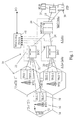
Figure 1 shows major elements of a GSM cellular mobile telephone
network 10, with additional equipment to facilitate monitoring of the network. For
the sake of clarity the telecommunications transmission lines for carrying user
voice and data signals are omitted; only the signalling links for control of
operation of the network, which are of interest in the context of this invention, are
shown.
Referring to Figure 1, the coverage area of the network 10 is organised
into location areas (only one of which is shown), each location area typically
containing several cells 14, which are the basic unit of division of the coverage
area for the purposes of radio spectrum management and are shown in Figure 1
as conventional idealised hexagons. The cells 14 are grouped into location
areas to facilitate routing of an incoming call to the handset 12. Each cell 14
contains a Base Station Transceiver (BTS) 16 which houses one or more radio
transceivers (TRXs 1-7) 18 for communicating with Mobile Handsets (MSs) 12
over the radio "air interface", and these transceivers are connected via "A-bis"
signalling links 20 to a Base Station Controller (BSC) 22 which may control
transceivers in more than one BTS 16. The sub-system comprising a BSC 22
and its associated BTSs 16 is sometimes referred to as a base station system
(BSS). The BSCs 22 are themselves co-ordinated via "A" signalling links 24 by
Mobile Switching Centres (MSCs) 26, which may control BSCs 22 in more than
one location area. The MSCs typically contain Visitor Location Registers (VLRs)
for co-ordinating services to MSs 12, and have links 28 carrying Mobile
Application Protocol (MAP) messages from the MSCs/VLRs 26 to Signal
Transfer Points (STPs) 30 providing signalling connections to other parts of the
network, and in particular to a Home Location Register (HLR) 31 for storing
subscriber information.
In the present example of the invention, signalling data which can be used
to determine the efficiency of operation of the network is obtained by equipment
48 for monitoring signalling messages traversing the A-bis links 20, the A links
24, and the MAP links 28. This signalling data is carried by different link level
protocols, depending on which signal links the data is on. For example, signals
on the A-bis links 20 are generally carried by Link Access Protocol - D channel
(LAPD), whereas signals on the A links 24 and the MAP links 28 are carried by
Message Transfer Part (MTP) protocol.
The monitoring equipment 48 includes a monitoring and analysis module
50 and a monitoring probe 32, as best seen in Figure 2, for passively monitoring
signalling messages traversing the A-bis, A links and the MAP links 20, 24 and
28, as described below. The monitoring is passive in the sense that the
operation of the links 20, 24 and 28 is undisturbed by the presence of the
monitoring system, which simply makes copies of some or all of the message
packets it observes traversing the links. The probe 32 is coupled to the links in
such a way that the operating characteristics of the links 20, 24 and 28 are not
significantly altered. In the case of an optical link, for example, the coupling may
comprise an optical power splitter and for an electrical link it may be a bridging
isolator.
As shown in Figure 2, the probe 32 has an input interface 34 which
receives and conditions the signal received over a line 36 from the coupling to
the relevant link 20, 24 or 28 and which supplies the signal to a processor/CPU
38 operating under the control of software program instructions in a program
store 40 and using a random access store 42. The processor 38 extracts
messages from the signal and performs some initial processing (e.g. error
checking and preliminary decoding). The messages are subsequently forwarded
via an interface 44 and a communications bus 46 to the monitoring and analysis
module 50 for any necessary additional decoding and for further analysis as
described below. This monitoring and analysis module provides a real-time
measurement data stream on a measurement interface 52. The probe 32 may
comprise, for example, components of an acceSS7 system equipment available
from Agilent Technologies for monitoring messages traversing SS7 signalling
networks.
Figure 3 shows part of the architecture of the probe 32 and the monitoring
and analysis module 50 in terms of functional modules involved in the processing
they perform. Referring to Figure 3, the data streams carried on the A-bis, A and
MAP links 20, 24 and 28 are received via for example E1 or T1 bearers (physical
cables) connected to the probe(s) 32, and data timeslots in those data streams
are identified and extracted in Timeslot Extractor and HDLC Framer module 58.
Since all signalling is carried by High-Level Data Link Control (HDLC) frames,
signalling channels (as opposed to channels carrying voice or data traffic) are
found by looking for timeslots carrying HDLC frames. An HDLC frame is
identified by a flag at the beginning of the frame. HDLC frames are passed,
together with information regarding the timeslots they relate to, to a Signalling
Channel Auto-Discovery Module 60 and to a Protocol Auto-Discovery Module 63,
as will be described more fully below.
The Signalling Channel Auto-Discovery Module 60 scans through all sub-rates
of all timeslots on all bearers looking for valid HDLC frames. A valid HDLC
frame is identified by valid checksum at the end of the frame. When such a valid
HDLC frame is found, an entry is made in a Channel Configuration Table 62, that
is stored in suitable non-volatile memory, that the channel on that particular
timeslot is likely to be signalling channel (since signalling channels use HDLC
frames).
Once a signalling channel or link has been found on a particular timeslot in
the signalling link, the protocol of the messages on that channel needs to be
determined. This is carried out by the Protocol Auto-Discovery Module 63. The
Protocol Auto-Discovery Module 63 receives the HDLC frames, together with
information regarding the timeslots they relate to, from the Timeslot Extractor and
HDLC Framer 58, as well as information from the Channel Configuration Table
62 indicating that a particular channel is likely to be a signalling channel. The
Protocol Auto-Discovery Module 63 thus scans HDLC frames to try to determine
which protocol is being carried by the particular channel. The Protocol Auto-Discovery
Module 63 utilises predetermined characteristics of the protocols
which have been stored in a memory 64. The predetermined characteristics
depend on the particular protocol being searched for. It should be pointed out
that, although in this implementation, only LAPD and MTP2 protocols are being
positively identified, other protocols (for example new protocols) may be present,
which would not be identified.
The Channel Configuration Table 62 generally includes a timeslot entry for
each channel that has been determined by the Signalling Channel Auto-Discovery
Module 60 to be likely to be a signalling channel and provides protocol
identification of the particular channel (Channel ID) to a Channel Selector 65.
The Channel Selector 65 receives the HDLC frames from the Timeslot Extractor
and HDLC Framer module 58 and, if it finds that the channel has been positively
identified by having a Channel ID stored in the Channel Configuration Table 62,
the Channel Selector 65 passes the frames on that particular channel on to
particular decoders 67, 69, according to the Channel ID, for further decoding and
analysis. For example, as shown in Figure 3, messages that are carried on a
channel that has been identified as carrying the LAPD protocol are passed to the
LAPD Message Decoder 67, whereas messages carried on a channel that has
been identified as carrying the MTP protocol are passed to the MTP Message
Decoder 69.
Turning now to Figure 4, there is shown a flowchart 70 of a method of
operation of Protocol Auto-Discovery Module 63, in conjunction with memory 64
and Channel Configuration Table 62, for determining protocols. The
characteristics used to identify the protocols depend, of course, on the particular
protocol and may include several different characteristics in order to produce a
positive identification. In this example, the protocols to be determined are LAPD
and MTP and the particular characteristics used for determining these protocols
are peculiar to them.
For example, in MTP, the bottom 6 bits of the 3rd octet constitutes the
length field. The MTP protocol can contain filler signal units (FISUs) having a
length of three Octets. Three Octet frames with this characteristic will never be
present in LAPD protocol. Thus, if a frame with a length of three octets has a
MTP length field of 0 then the frame is an MTP FISU. In an LAPD frame, the top
six bits of the first octet constitutes the Service Access Point Indicator (SAPI). A
SAPI having a valid value of LAPD_SAPI, which is a predefined characteristic
equal to the SAPI of interest, indicates that the protocol is LAPD.
Thus, as shown in Figure 4, when the Protocol Auto-Discovery Module 63
receives a new frame (step 72), it first checks (step 74) whether it is a valid
HDLC frame by looking for a valid checksum at the end of the frame. If it is a
valid HDLC frame, the Channel Configuration Table 62 is searched (step 76) to
determine whether timeslot entry information for that frame has already been
entered in the Channel Table 63 by the Signalling Channel Auto-Discovery
Module 60. If a timeslot entry is found, then the protocol of the frame is
determined by subroutine 82, as will more fully described below. If the timeslot
entry is not found for that frame, then such a timeslot entry is created (step 80)
and then the protocol of the frame is determined by subroutine 82.
Figure 5 shows a flowchart of subroutine 82 for determining the protocol of
a frame. As shown in this Figure, the process starts (step 100) by determining
the length of a frame (step 102). Depending on the frame length, different
options are available (step 104). If the frame length is equal to three octets
(bytes), the process flow then determines whether the third octet has a value of
zero (step 106). As mentioned above, if the value of the third octet is zero, then
the frame is an MTP FISU and a protocol identification of MTP is returned (step
108). If, however, the third octet has a different value (step 106), then a protocol
identification of UNKNOWN is returned (step 110).
Returning to step 104, if the frame length is less than three octets or
greater than or equal to sixty-six octets, then as mentioned above, the frame is
ambiguous, so the UNKNOWN identification is returned (Step 118). If, however,
the frame length is between three and sixty-six octets, then the protocol might be
LAPD, but this needs to be checked further. Accordingly, the process flow
proceeds to step 112, where the bottom six bits of the third octet are checked. If
they are not equal to the frame length minus three, then, the frame is definitely
not MTP, and the process flow moves on to step 114. On the other hand, if the
bottom six bits of the third octet are equal to the frame length minus three, then
the frame could be LAPD or MTP and the UNKNOWN identification is returned
(Step 118). In step 114, the top six bits of the first octet are checked to see
whether they have a SAPI value of LAPD_SAPI. If so, then a protocol
identification of LAPD is returned (step 116); if not, then the UNKNOWN
identification is returned (Step 118).
Thus, the subroutine 82 returns a protocol identification of LAPD, MTP or
UNKNOWN. Returning now to Figure 4, the returned protocol identification is
considered in step 84. If it is UNKNOWN, then the process flow returns to step
72 to await receipt of a new frame. If, however, a protocol identification of LAPD
or MTP is provided, then Channel Configuration Table 62 is accessed by the
Protocol Auto-Discovery Module 63. The Channel Configuration Table 62
includes an LAPD Count entry, an MTP Count entry and Channel ID entry for
each timeslot entry. The Count values are used to provide a confidence
measure for a particular identification of a channel (Channel ID). Only one of the
count entries can be greater than zero, with a threshold value being preset and a
limit value being preset for each Count entry. The threshold value is used to
provide a confidence measure that a sufficient number of frames have been
identified as being of the same protocol that the channel can be identified as
carrying that particular protocol (Channel ID). The limit value is preset so that the
Count entry does not keep getting incremented infinitely. Initially, of course, the
Channel ID entry is UNKNOWN, until the threshold value is reached by one of
the Count entries, when the Channel ID is changed to that protocol.
Thus, if a protocol identification of LAPD is received from subroutine 82 for
a channel (timeslot), the LAPD Count and the MTP Count for that channel are
read (step 88). If the LAPD Count is below the preset limit (LIMIT) and the MTP
Count entry is zero, then the LAPD Count is incremented by one. If, however,
the MTP Count is greater than zero, then the MTP Count is decremented by one.
Similarly, if a protocol identification of MTP is received from subroutine 82 for a
channel (timeslot), the LAPD Count and the MTP Count for that channel are read
(step 86). If the MTP Count is below the preset limit (LIMIT) and the LAPD
Count entry is zero, then the MTP Count is incremented by one. If, however, the
LAPD Count is greater than zero, then the LAPD Count is decremented by one.
Returning to step 74, if a valid checksum is not found at the end of the
received new frame, indicating that it is not a valid HDLC frame, the Channel
Configuration Table 62 is searched to determine whether there is a timeslot entry
for that frame (step 94). If such a timeslot entry is not found (step 96), indicating
that the channel was not considered to be a signalling link, then the process
reverts to step 72 to receive the next frame. If, however, a timeslot entry is found
(step 96) for that channel, indicating that the channel was considered to be a
signalling link, then whichever of the Count entries for that timeslot is greater
than zero is decremented by one (step 98).
From steps 86, 88 and 98, the process flow moves to step 90, where the
LAPD Count and the MTP Count entries are considered. If either of the Count
entries is equal to or above the threshold value (THRESHOLD), then the
Channel ID is set (or maintained) to the appropriate identification. If however,
either of the Count entries is below the threshold value and the Channel ID was
previously set to that particular identification, then the Channel ID is set to
UNKNOWN, indicating that the Count for that protocol has dropped below the
threshold value, so that the identification of that channel is no longer sure (to the
extent set by the threshold value).
The Channel ID for that timeslot is output (step 92) to the Channel
Selector 65 (see Figure 3), when it accesses the Channel Configuration Table
62, so that the Channel Selector 65 can switch messages on that Channel to the
appropriate decoders 67, 69.
It will be apparent that the predetermined characteristics used to identify
the protocols may be a single characteristic or a combination of characteristics
sufficient to provide a definite identification. Of course not all messages in a
particular protocol will necessarily include the characteristic, but, if a message
doesn't include any of the characterisitics, then it is simply considered to be
unidentified. As long as the characteristic tests are chosen so as to be relatively
common, then enough of the messages on the particular link should be positively
identified to enable the link to be identified as having the particular protocol.
It will also be appreciated that although only one particular embodiment of
the invention has been described in detail, various modifications and
improvements can be made by a person skilled in the art without departing from
the scope of the present invention. For example, various embodiments of the
invention can be implemented as a computer program product for use with a
computer system, the computer program product being, for example, a series of
computer instructions stored on a tangible data recording medium, such as a
diskette, CD-ROM, ROM, or fixed disk, or embodied in a computer data signal,
the signal being transmitted over a tangible medium or a wireless medium, for
example microwave or infrared. The series of computer instructions can
constitute all or part of the functionality described above, and can also be stored
in any memory device, volatile or non-volatile, such as semiconductor, magnetic,
optical or other memory device.