EP1392034A1 - Equipment, system and method for communication via multiple paths using address notification scheme - Google Patents
Equipment, system and method for communication via multiple paths using address notification scheme Download PDFInfo
- Publication number
- EP1392034A1 EP1392034A1 EP20030018617 EP03018617A EP1392034A1 EP 1392034 A1 EP1392034 A1 EP 1392034A1 EP 20030018617 EP20030018617 EP 20030018617 EP 03018617 A EP03018617 A EP 03018617A EP 1392034 A1 EP1392034 A1 EP 1392034A1
- Authority
- EP
- European Patent Office
- Prior art keywords
- host
- addresses
- reception
- transmission
- packet
- Prior art date
- Legal status (The legal status is an assumption and is not a legal conclusion. Google has not performed a legal analysis and makes no representation as to the accuracy of the status listed.)
- Granted
Links
Images


Classifications
-
- H—ELECTRICITY
- H04—ELECTRIC COMMUNICATION TECHNIQUE
- H04L—TRANSMISSION OF DIGITAL INFORMATION, e.g. TELEGRAPHIC COMMUNICATION
- H04L63/00—Network architectures or network communication protocols for network security
- H04L63/04—Network architectures or network communication protocols for network security for providing a confidential data exchange among entities communicating through data packet networks
- H04L63/0428—Network architectures or network communication protocols for network security for providing a confidential data exchange among entities communicating through data packet networks wherein the data content is protected, e.g. by encrypting or encapsulating the payload
-
- H—ELECTRICITY
- H04—ELECTRIC COMMUNICATION TECHNIQUE
- H04L—TRANSMISSION OF DIGITAL INFORMATION, e.g. TELEGRAPHIC COMMUNICATION
- H04L61/00—Network arrangements, protocols or services for addressing or naming
- H04L61/45—Network directories; Name-to-address mapping
- H04L61/4505—Network directories; Name-to-address mapping using standardised directories; using standardised directory access protocols
- H04L61/4511—Network directories; Name-to-address mapping using standardised directories; using standardised directory access protocols using domain name system [DNS]
-
- H—ELECTRICITY
- H04—ELECTRIC COMMUNICATION TECHNIQUE
- H04L—TRANSMISSION OF DIGITAL INFORMATION, e.g. TELEGRAPHIC COMMUNICATION
- H04L69/00—Network arrangements, protocols or services independent of the application payload and not provided for in the other groups of this subclass
- H04L69/16—Implementation or adaptation of Internet protocol [IP], of transmission control protocol [TCP] or of user datagram protocol [UDP]
- H04L69/163—In-band adaptation of TCP data exchange; In-band control procedures
-
- H—ELECTRICITY
- H04—ELECTRIC COMMUNICATION TECHNIQUE
- H04L—TRANSMISSION OF DIGITAL INFORMATION, e.g. TELEGRAPHIC COMMUNICATION
- H04L9/00—Cryptographic mechanisms or cryptographic arrangements for secret or secure communications; Network security protocols
- H04L9/40—Network security protocols
-
- H—ELECTRICITY
- H04—ELECTRIC COMMUNICATION TECHNIQUE
- H04L—TRANSMISSION OF DIGITAL INFORMATION, e.g. TELEGRAPHIC COMMUNICATION
- H04L1/00—Arrangements for detecting or preventing errors in the information received
- H04L1/12—Arrangements for detecting or preventing errors in the information received by using return channel
- H04L1/16—Arrangements for detecting or preventing errors in the information received by using return channel in which the return channel carries supervisory signals, e.g. repetition request signals
- H04L1/18—Automatic repetition systems, e.g. Van Duuren systems
-
- H—ELECTRICITY
- H04—ELECTRIC COMMUNICATION TECHNIQUE
- H04L—TRANSMISSION OF DIGITAL INFORMATION, e.g. TELEGRAPHIC COMMUNICATION
- H04L61/00—Network arrangements, protocols or services for addressing or naming
- H04L61/50—Address allocation
-
- H—ELECTRICITY
- H04—ELECTRIC COMMUNICATION TECHNIQUE
- H04L—TRANSMISSION OF DIGITAL INFORMATION, e.g. TELEGRAPHIC COMMUNICATION
- H04L69/00—Network arrangements, protocols or services independent of the application payload and not provided for in the other groups of this subclass
- H04L69/14—Multichannel or multilink protocols
-
- H—ELECTRICITY
- H04—ELECTRIC COMMUNICATION TECHNIQUE
- H04L—TRANSMISSION OF DIGITAL INFORMATION, e.g. TELEGRAPHIC COMMUNICATION
- H04L69/00—Network arrangements, protocols or services independent of the application payload and not provided for in the other groups of this subclass
- H04L69/16—Implementation or adaptation of Internet protocol [IP], of transmission control protocol [TCP] or of user datagram protocol [UDP]
Definitions
- the present invention relates to a communication equipment, a communication system, and a communication method.
- a communication equipment that performs packet communication using an Internet protocol (IP) address uses one IP address for each communication.
- IP Internet protocol
- a communication procedure to be performed by a communication equipment to which an IP address is provided, respectively, is described as taking a host A and host B as an example.
- the host A sets its own IP address as the source address, and transmits to the host B a packet where an IP address of the host B is set as the destination address to start communication.
- the host B sets the source address included in the received packet as the destination address of the packet, and sets the destination address included in the received packet as the source address of the packet, and then transmits the packet to the host A.
- the host A and host B communicate.
- the route for packet reception/ transmission is determined by routers that exist between the communication equipments, based on the source address or destination address of each packet.
- an IP address is, normally, provided for each media in an IP network.
- a local area network forms one media, and an IP address is provided for each LAN.
- the wireless LAN is an area network where a base station is connected to a fixed LAN, and where a mobile communication equipment having a wireless LAN card performs wireless communication with a LAN by connecting to the base station.
- a communication equipment can use only one IP address for each communication.
- a packet reception/ transmission route determined by a router based on a source address or a destination address of a packet is almost always fixed to one route even though there may be a plurality of routes between communication equipments. Accordingly, a communication equipment cannot perform packet reception/ transmission using a more preferable route or packet reception/ transmission using a plurality of routes. As a result, effective data transfer cannot be performed.
- a communication equipment cannot use an IP address that is provided within one LAN, within another LAN.
- the same IP address can be used if the communication equipment exists within the same wireless LAN area even if the communication equipment moves and changes the base station connection.
- the new base station connects to a wireless LAN, which is different from the previously connected wireless LAN. As a result, the communication equipment becomes unable to use the IP address provided for the previously connected wireless LAN.
- the communication equipment must acquire a new IP address that can be used with the newly connected wireless LAN. Also, there is a problem in that the communication equipment cannot maintain prior communication. That is, the communication equipment cannot guarantee continuous mobile communication.
- Mobile IP has been proposed as a technology for solving such problems. However, a specific function for using Mobile IP must be provided for the IP network in advance.
- An object of the present invention is to provide a communication equipment, a communication system, and a communication method, which can perform effective data transfer and mobile communication.
- a communication system of the present invention comprises a communication equipment provided with a plurality of addresses, and a target equipment provided with a plurality of target equipment addresses, and configured to perform packet reception/ transmission from/ to the communication equipment.
- the communication equipment of the present invention comprises a reception/ transmission unit configured to notify the target equipment of a plurality of provided addresses, acquire a plurality of target equipment addresses, from the target equipment, and perform packet reception/ transmission using the plurality of provided addresses and the plurality of acquired target equipment addresses; and a controller configured to select the target equipment address to be used by the reception/transmission unit, and control the reception/ transmission unit to perform the packet reception/ transmission using a selected target equipment address.
- the target equipment is a target communication equipment for performing packet reception/ transmission.
- the target equipment address is an address provided for the target equipment.
- a plurality of addresses is provided for the communication equipment.
- the reception/ transmission unit notifies the target equipment, which is the target for communication, of the plurality of addresses.
- the reception/ transmission unit acquires the plurality of target equipment addresses.
- the reception/ transmission unit then performs packet reception/transmission using the plurality of addresses provided for the communication equipment and the plurality of acquired target equipment addresses.
- the controller selects the target equipment address to be used by the reception/transmission unit and controls the reception/ transmission unit to perform packet reception/ transmission using it.
- the communication equipment may perform packet reception/ transmission via a plurality of routes by using a plurality of addresses provided for itself and the plurality of target equipment addresses.
- the communication equipment may perform high-speed data transfer, that is, the communication equipment may perform more effective data transfer.
- the communication equipment may use a plurality of addresses provided for itself even when it moves between different networks. Therefore, the communication equipment does not require the acquisition of a new address, and it may continue communication.
- the communication equipment may use the plurality of target equipment addresses even when the target equipment moves between different networks. Therefore, the communication equipment may continue to maintain prior communication. Accordingly, the communication equipment may guarantee continuous mobile communication.
- a communication method of the present invention comprises notifying a target equipment of a plurality of addresses provided for a communication equipment, acquiring a plurality of target equipment addresses provided for the target equipment, selecting the target equipment address to be used for packet reception/ transmission, and performing the packet reception/transmission using the plurality of addresses provided for the communication equipment and a selected target equipment addresses.
- the communication equipment may perform packet reception/ transmission via the plurality of routes by using a plurality of addresses provided for itself and the plurality of target equipment addresses.
- the communication equipment may perform high-speed data transfer, that is, may perform more effective data transfer.
- the communication equipment may use the plurality of addresses provided for itself even when it moves between different networks. Therefore, the communication equipment does not require acquiring a new address, and it may continue communication.
- the communication equipment may use the plurality of target equipment addresses even when the target equipment moves between different networks. Therefore, the communication equipment may continue to maintain prior communication. Accordingly, the communication equipment may guarantee continuous mobile communication.
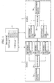
- a communication system comprises a host A 1, a host B 2, and a domain name system (DNS) server 3.
- the host A 1 and the host B 2 exist in different networks.
- the host A 1, the host B 2, and the DNS server 3 are connected via a network.
- the host A 1 and the host B2 are communication equipments, such as a terminal equipment or a server that perform packet reception/ transmission.
- the host B 2 is a target equipment for performing packet reception/ transmission in view of the host A1; and the host A 1 is a target equipment in view of the host B 2.
- FIG. 1 only two hosts are illustrated in order to simplify the explanation, however, there are more hosts in the communication system.
- IP addresses are provided for the host A 1 and the host B 2, respectively.
- a plurality of IP addresses is called "a group of IP addresses" when they are referred to collectively.
- IP addresses may be provided manually when setting up the host A 1 or the host B2, for example.
- IP addresses may be provided through a dynamic host configuration protocol (DHCP) when the host A 1 or the host B 2 is activated.
- IP addresses may also be provided through a point to point protocol (PPP) when the host A 1 or host B 2 connects to the network by a dial up connection, or the like.
- ISP Internet service provider
- the host A 1 and the host B 2 may connect to the network managed by a plurality of Internet service providers in order to acquire IP addresses managed by respective Internet service providers.
- the IP addresses of the host B 2 are target equipment addresses for the host A 1; and the IP addresses of the host A 1 are target equipment addresses for the host B 2.
- the host A 1 and the host B 2 associate the plurality of provided IP addresses with domain names, and register them in the DNS server 3.
- the host A 1 and the host B 2 update the IP addresses registered in the DNS server 3 and register the latest IP address by using a dynamic DNS (see request for comments (RFC) 2136).
- RRC request for comments
- the DNS server 3 associates and stores a plurality of IP addresses provided for the host A 1 and for the host B 2 with the domain names of the host A 1 and the host B 2, respectively. As shown in FIG. 1, the DNS server 3 associates and stores the domain name of the host A 1 "hostA.our.jp" with a plurality of IP addresses provided for the host A 1 "220.220.1.1, 230.221.1.1, and 240.222.1.1". In addition, the DNS server 3 associates and stores the domain name of the host B 2 "hostB.you.jp" with a plurality of IP addresses provided for the host B 2 "220.240.2.2 and 220.240.1.1".
- the host A 1 and the host B 2 comprise transmission buffers 1a and 2a, controllers 1b and 2b, and a plurality of reception/transmission units 1c through 1e and 2c and 2d, respectively.
- the reception/ transmission units 1c through 1e, 2c, and 2d perform packet reception/ transmission.
- An IP address is provided for each of the reception/ transmission units 1c through 1e, 2c, and 2d, respectively. More specifically, one of the plurality of IP addresses provided for the host A 1 is provided for each of the reception/ transmission units 1c through 1e, respectively. Similarly, one of the plurality of IP addresses provided for the host B 2 is provided for each of the reception/ transmission units 2c and 2d, respectively.
- the reception/ transmission units 1c through 1e notify the host B 2, of a plurality of IP addresses provided for the host A 1. Then, the reception/ transmission units 2c and 2d acquire a plurality of IP addresses provided for the host A 1 as the target equipment addresses, from the host A 1, which is the target equipment. Similarly, the reception/ transmission units 2c and 2d notify the host A 1, of a plurality IP addresses provided for the host B 2. Then, the reception/ transmission units 1c through 1e acquire a plurality of IP addresses provided for the host B 2 as the target equipment addresses, from the host B 2, which is the target equipment.
- the controllers 1b and 2b control the reception/transmission units 1c through 1e and 2c and 2d, respectively. More specifically, the controllers 1b and 2b select target equipment addresses to be used by the reception/ transmission units 1c through 1e and 2c and 2d, and control the reception/transmission units 1c through 1e and 2c and 2d to perform packet reception/ transmission using the selected target equipment addresses, respectively. In addition, the controllers 1b and 2b generate packets.
- the transmission buffers 1a and 2a store data to be transmitted to the target equipment from the host A 1 and the host B 2, respectively.
- the host A 1 and the host B 2 notify the target equipment of a plurality of IP addresses provided for themselves, respectively, and acquire from the target equipment a plurality of IP addresses provided for the target equipment.
- the host A 1 attempts to start communication is described as an example.
- the controller 1b of the host A 1 instructs the reception/transmission units 1c through 1e to inquire after a group of IP addresses of the host B 2 from the DNS server 3, using the domain name of the host B 2 as a key.
- the controller 1b stores the domain name of the host B 2 through manual setting or the like.
- the reception/ transmission units 1c through 1e transmit inquiry packets to the DNS server 3.
- the DNS server 3 transmits packets including a group of IP addresses of the host B 2 to the reception/ transmission units 1c through 1e.
- the controller 1b acquires a group of IP addresses of the host B 2 from the packet received by the reception/ transmission units 1c through 1e.
- the controller 1b creates a notification packet including a group of available IP addresses provided for the host A 1, in order to start communication.
- the controller 1b sets one of the IP addresses included in the acquired group of IP addresses of the host B 2, as a destination address of the notification packet.
- the controller 1b inputs a created notification packet to one of the reception/ transmission units 1c through 1e.
- One of the reception/ transmission units 1c through 1e transmits the notification packet to the host B 2 to notify the host B 2, of a group of available IP addresses provided for the host A 1.
- the reception/ transmission unit 2c or 2d of the host B 2 to which the destination address of the notification packet is provided receives the notification packet and acquires a group of available IP addresses provided for the host A 1.
- the reception/ transmission unit 2c or 2d inputs the received notification packet to the controller 2b.
- the controller 2b acquires a group of available IP addresses provided for the host A 1 from the notification packet. Subsequently, the controller 2b recognizes that all the packets where addresses of the acquired group of IP addresses, provided for the host A 1 are set as the source addresses, are the ones transmitted from the host A 1.
- the controller 2b creates a response packet corresponding to the notification packet for starting communication.
- the controller 2b creates the response packet including a group of available IP addresses provided for the host B 2.
- the controller 2b sets the destination address of the notification packet received from the host A 1 as a source address.
- the controller 2b sets one of the IP addresses included in the acquired group of IP addresses of the host A 1 as a destination address of the response packet.
- the controller 2b inputs the created response packet to the reception/ transmission unit 2c or 2d to which is provided the source address of the response packet.
- the reception/ transmission unit 2c or 2d transmits the response packet to the host A 1 to notify of a group of available IP addresses provided for the host B 2.
- One of the reception/ transmission units 1c through 1e of the host A 1 to which the destination address of the response packet is provided receives the response packet, and acquires a group of available IP addresses provided for the host B2 .
- One of the reception/ transmission units 1c through 1e then inputs the received response packet to the controller 1b.
- the controller 1b acquires a group of available IP addresses provided for the host B 2 from the response packet. Subsequently, the controller 1b recognizes that all the packets where addresses of the acquired group of IP addresses, provided for the host B 2 are set as the source addresses, are the ones transmitted from the host B 2 .
- the host A 1 recognizes a group of IP addresses included in the response packet from the host B 2, as a group of IP addresses of the host B 2, since the available IP addresses may be changed, although a group of IP addresses of the host B 2 is acquired from the DNS server 3. In this manner, the host A 1 and the host B 2 notify the target equipment of a plurality of available IP addresses provided for themselves, acquire a plurality of available IP addresses provided for the target equipment from the target equipment, and then communication is started.
- the controllers 1b and 2b may set a group of IP addresses as an option parameter of a transmission control protocol (TCP) header, for example, when creating the notification packet or the response packet including a group of IP addresses (see RFC 793).
- TCP transmission control protocol
- the controllers 1b and 2b may set a group of IP addresses as an optional extended header or a data field, in the case of an IP version 6 (Ipv6) packet.
- the controllers 1b and 2b may set a group of IP addresses as an option parameter of a header or a data field, in the case of an IPv4 packet.
- the host A 1 and the host B 2 notify the target equipment of a group of available IP addresses, and acquire a group of available IP addresses from the target equipment not only when starting communication but also in the case where a group of available IP addresses has changed.
- a group of IP addresses such as providing a new IP address for the host A 1 or for the host B 2, or becoming available from an unavailable IP address.
- a deletion case of a group of IP addresses such as becoming unavailable from an available IP address provided for the host A 1 or for the host B 2.
- the host A 1 and the host B 2 may regularly notify the target equipment of a group of IP addresses and acquire a group of IP addresses from the target equipment, in order to confirm a group of available IP addresses.
- the controller 1b creates an notification packet including the added IP address.
- One of the reception/ transmission units 1c through 1e then transmit the notification packet to the host B 2 in order to notify of a group of available IP addresses provided for the host A 1 including the added IP address.
- the reception/ transmission unit 2c or 2d of the host B 2 receives the notification packet and acquires a group of available IP addresses provided for the host A 1 including the added IP address.
- the reception/ transmission unit 2c or 2d inputs the received notification packet to the controller 2b.
- the controller 2b acquires the added IP address , and subsequently recognizes that the packet where the added IP address is set as the source address is also a packet transmitted from the host A 1.
- the controller 2b creates an acknowledgement packet where the added IP address is set as a destination address.
- the reception/ transmission unit 2c or 2d then transmits the acknowledgement packet to the host A 1.
- the controller 1b of the host A 1 may confirm that the host B 2 has acknowledged the added packet.
- the controller 2b when the IP address provided for the host B 2 becomes unavailable and is deleted, for example, the controller 2b creates a notification packet where the deleted IP address is not included.
- the reception/ transmission unit 2c or 2d then transmits an notification packet to the host A 1 in order to notify of a group of currently available IP addresses provided for the host B 2 where the deleted IP address is not included.
- One of the reception/ transmission units 1c through 1e of the host A 1 receive the notification packet and acquires a group of currently available IP addresses provided for the host B 2 where the deleted IP address is not included.
- One of the reception/ transmission units 1c through 1e inputs the received notification packet to the controller 1b
- the controller 1b may recognize that the IP address is deleted through acquiring a group of IP addresses where the deleted IP address is not included.
- the host B 2 may implicitly notify the host A 1, of the deletion of available IP address.
- the host A 1 may transmit a packet, in order to notify the host B 2 , of recognition the deletion of the IP address , however, it is not always necessary to transmit the packet, since a packet destined for the deleted IP address is not transferred to the host B 2, and the unavailable address becomes gradually unused.
- the host A 1 and the host B 2 notify the target equipment of a plurality of available IP addresses provided for themselves, acquire a plurality of available IP addresses provided for the target equipment from the target equipment, and then start communication.
- a case where the host A 1 transmits data and the host B 2 receives data is described as an example.
- the controller 1b of the host A 1 acquires data from the transmission buffer 1a to create a packet.
- the controller 1b selects an IP address to be used by the reception/ transmission units 1c through 1e from the acquired group of IP addresses of the host B 2, and sets the selected IP address as a destination address.
- the controller 1b also selects one of the reception/ transmission units 1c through 1e, which transmits the packet, and sets the IP address provided for the selected one of the reception/ transmission units 1c through 1e, as a source address.
- the controller 1b inputs a created packet to the selected one of the reception/transmission units 1c through 1e.
- One of the reception/transmission units 1c through 1e then transmits the packet.
- the reception/ transmission unit 2c or 2d of the host B 2 receives the packet transmitted from the host A 1.
- the reception/ transmission unit 2c or 2d inputs the received packet to the controller 2b.
- the controller 2b checks the source address of the received packet with the acquired group of IP addresses of the host A 1. When the source address of the received packet is included in the group of IP addresses of the host A 1, the controller 2b recognizes that the packet is a packet transmitted from the host A 1. Note that the packet reception/transmission in the case where the host B 2 transmits data and the host A 1 receives data may be performed in the same manner.
- a network 4 where the host A 1 exists and a network 5 where the host B 2 exists are connected via a plurality of networks 6a and 6b.
- the controllers 1b and 2b control a plurality of reception/ transmission units 1c through 1e, 2c, and 2e to perform packet reception/transmission in parallel via a plurality of routes .
- a plurality of reception/ transmission units 1c through 1e, 2c, and 2d then transmit the packet input from the controllers 1b and 2b in parallel via a plurality of routes.
- the controllers 1b and 2b preferably encrypt the data included in the packet to be received/ transmitted, in preparation for the case where another host begins to use one of the IP addresses which was previously used by the host A 1 and the host B 2.
- the controllers 1b and 2b not only encrypt the data, but also control the reception/transmission units 1c through 1e, 2c, and 2d to reject the reception of unencrypted packets. By this communication affected by another hosts can be prevented.
- the controllers 1b and 2b select the target equipment addresses when performing communication, and the controllers 1b and 2b preferably combine a plurality of addresses provided for themselves with a plurality of target equipment addresses. And, the controllers 1b and 2b select the combination to be used by the reception/ transmission units 1c through 1e, 2c, and 2d, from the combinations. Then the controllers 1b and 2b control the reception/ transmission units 1c through 1e, 2c, and 2d to perform packet reception/ transmission by using the selected combinations. As described above, there are a plurality of routes between the host A 1 and the host B 2. Therefore, the controllers 1b and 2b select the combination of the plurality of address provided for themselves and the plurality of target equipment addresses, so as to perform communication by selecting the most appropriate route from a plurality of routes between the host A 1 and the host B 2.
- FIG. 3 A first selection method for selecting the combination of the addresses is described by using FIG. 3.
- the first selection method is described by taking the operation of the host A 1 as an example.
- the controller 1b of the host A 1 selects the combinations of the IP addresses of the host A 1 and the IP addresses of the host B 2 for respective reception/ transmission units 1c through 1e from the six kinds of combinations.
- the controller 1b then instructs the respective reception/ transmission units 1c through 1e to connect the TCP connection to the IP address of the host B 2 included in the selected combination, and perform packet reception/ transmission.
- the reception/ transmission units 1c through 1e connect the TCP connection and perform packet reception/ transmission according to the instruction.
- the controller 1b monitors the state where the reception/transmission units 1c through 1e perform packet reception/transmission from/ to the host B 2, and measures the packet transmission efficiency.
- the controller 1b may measure the transmission efficiency through the TCP.
- the controller 1b determines disconnection of the TCP connection and abortion of the communication of the combinations for which the packet transmission efficiency is low.
- the controller 1b then instructs the reception/transmission units 1c through 1e, which connect the determined connection to disconnect the TCP connection and abort the communication.
- the controller 1b monitors the state of the packet reception/ transmission, and determines disconnection of the TCP connection of the combinations where the transmission efficiency is less than the prescribed transmission efficiency threshold.
- the reception/transmission units 1c through 1e disconnect the TCP connection and abort communication, according to the instruction from the controller 1b. Note that the TCP connection of the combinations where the packet transmission efficiency is high are not disconnected and communication of these combinations continue.
- the controller 1b selects the combination of the IP addresses of the host A 1 and the IP addresses of the host B 2 that has not yet been selected for the reception/ transmission units 1c through 1e where communication has been aborted.
- the controller 1b then instructs the respective reception/transmission units 1c through 1e to re-connect the TCP connection to the IP address of the host B 2 included in the selected combination, and perform packet reception/transmission.
- the host A 1 performs packet reception/ transmission, monitors the state, disconnects the TCP connection where the packet transmission efficiency is low, and selects other combinations.
- the host A may continue packet reception/ transmission while giving priority to the combination of the IP addresses of the host A 1 and the IP addresses of the host B 2 having high transmission efficiency, through repetition of such sequential operations.
- the host B 2 may perform packet reception/transmission by selecting the most appropriate combination of IP addresses of the host A 1 and the IP addresses of the host B 2, in the same manner.
- FIGS. 4A and 4B a second selection method for selecting combinations of the IP addresses is described by using FIGS. 4A and 4B.
- FIGS. 4A and 4B for simplifying the explanation, components not needed for explanation of the second selection method are omitted, and IP addresses are indicated with two-digit numbers.
- the second selection method is described taking the operation of the host A 1 as an example.
- the controller 1b of the host A 1 stores rates of all the combinations of the IP addresses of the host A 1 and the IP addresses of the host B 2 which are used for packet reception/ transmission (hereafter, referred to as "usage rate"). More specifically, the controller 1b comprises a table 11b shown in FIG. 4B.
- the controller 1b selects a combination of IP addresses of the host A 1 and the IP addresses of the host B 2 to be used for packet reception/ transmission to attain the same usage rates, as stored in the table 11b, when the host A 1 performs the packet reception/ transmission.
- the controller 1b may select a combination of IP addresses of the host A 1 and the IP addresses of the host B 2 by using random numbers , for example.
- the controller 1b acquires data from the transmission buffer 1a, and creates a packet to be transmitted by using the selected combination of IP addresses.
- the controller 1b adds identification data such as a tag which indicates the combination of IP addresses of the host A 1 and the IP addresses of the host B 2 to be used for transmitting the created packet, to the data used for packet creation and stored in the transmission buffer 1a. In other words, the controller 1b adds the identification data such as a tag, which indicates the combination of IP addresses of the packet transmitted, to the data used for packet creation in the transmission buffer 1a.
- the controller 1b inputs the created packet to the reception/ transmission units 1c through 1e, which is provided with the IP addresses of the host A 1 included in the selected combination.
- the reception/ transmission units 1c through 1e transmit a packet 9a to the host B 2.
- the reception/transmission unit 2c or 2d which is provided with the IP addresses of the host B 2 included in the selected combination receives the packet 9a, and transmits an acknowledgement signal (ACK signal) 9b to the host A 1, in response to the packet 9a.
- the reception/ transmission unit 1c through 1e receives the ACK signal 9b transmitted from the host B 2, and then inputs it to the controller 1b
- the controller 1b may confirm that the packet corresponding to the ACK signal has been successfully transmitted and received by the host B 2 .
- the controller 1b detects and deletes the data used for creating the packet corresponding to the ACK signal, from the transmission buffer 1a.
- the controller 1b retrieves the transmission buffer 1a, and detects the data used for creating the packet, which was transmitted following the packet corresponding to the finally received ACK signal. The controller 1b determines that the packet including detected data did not successfully arrive at the host B 2. The controller 1b then acquires the combination of the IP addresses of the host A 1 and the IP addresses of the host B 2 used for transmitting the packet including the data, based on the identification data such as a tag added to the detected data.
- the controller 1b decreases the usage rate of the acquired combination of the IP addresses, and increases the usage rates of other combinations of the IP addresses. For example, the controller 1b divides the decreased usage rate by the number of other combinations, and adds the quotient to all other usage rates of the combinations evenly.
- the controller 1b updates the usage rate in the table 11b according to the controlled result. Since the controller 1b selects a combination of the IP addresses by using the usage rate stored in the table 11b when transmitting a packet, the usage rate updated in this manner is used for selecting a combination of the IP addresses.
- the controller 1b controls the reception/transmission units 1c through 1e to retransmit a packet including the detected data to the host B 2. The reception/transmission units 1c through 1e then retransmits the packet to the host B 2.
- the host A 1 may increase the usage rate of the combinations of IP addresses of the host A 1 and the IP addresses of the host B 2 where the packet may easily arrive at the host B 2, and retransmission is not required, through repetition of such sequential operations .
- the host A may perform packet reception/ transmission by using a combination of IP addresses of the host A 1 and the IP addresses of the host B 2 where the packet may easily arrive at the host B 2.
- the host A 1 may perform packet reception/ transmission by using a route where the packet may easily arrive at the host B 2, and retransmission is not required. Accordingly, the host A 1 may improve the packet transmission efficiency.
- the host B 2 may perform packet reception/ transmission by selecting the most appropriate combination of the IP addresses of the host A 1 and the IP addresses of the host B 2, in the same manner.
- the second selection method may be implemented by extending the TCP, for example.
- the usage rate in the initial state may be set to other values.
- the packet transmission rate may be different for each route determined by a combination of IP addresses of the host A 1 and IP addresses of the host B 2.
- the usage rate in the initial state are preferably set in proportion to the transmission rate of each route determined by a combination of IP addresses of the host A 1 and the IP addresses of the host B 2.
- the controller 1b of the host A 1 creates a packet where the transmission rate for respective reception/transmission units 1c through 1e relative to the total transmission rate of all reception/ transmission units 1c through 1e corresponds to the IP addresses provided for respective reception/ transmission units 1c through 1e.
- One of the reception/ transmission units 1c through 1e then transmit the packet to the host B 2.
- the controller 2b of the host B 2 creates a similar packet, and One of the reception/transmission units 2c and 2d transmit it.
- the controllers 1b and 2b then calculate a product of their own transmission rate and the transmission rate of the target equipment for every combination of IP addresses of the host A 1 and the IP addresses of the host B 2, and may use the result as the initial values of the usage rates.
- the controller 1b calculates a product of the transmission rates of respective reception/ transmission units 1c through 1e relative to the total transmission rate of all reception/ transmission units 1c through 1e of the host A 1, and the transmission rate of respective reception/transmission units 2c and 2d relative to the total transmission rate of all reception/ transmission units 2c and 2d of the host B 2 transmitted from the host B 2, as an initial value of the usage rate for every combination of the IP addresses of the host A 1 and the IP addresses for the host B 2.
- the controller 2b calculates products of the transmission rates of respective reception/ transmission units 2c and 2d relative to the total transmission rate of all reception/ transmission units 2c and 2d of the host B 2 and the transmission rates of respective reception/ transmission units 1c through 1e relative to the total transmission rate of all reception/ transmission units 1c through 1e of the host A 1 transmitted from the host A 1, as an initial value of the usage for every combination of the IP addresses of the host A 1 and the IP addresses of the host B 2.
- initial values of the usage rates may be set by using the transmission rate of the network where each route determined by a combination of the addresses of the host A 1 and the addresses of the host B 2 exists, other than the transmission rate of the reception/ transmission units 1c through 1e, 2c, and 2d.
- the effective transmission rate may be lower, for example, 2 Mbps . Therefore, the initial value of the usage rate is preferably set, by using the effective transmission rate of every network.
- the usage rate in the initial state when the usage rate in the initial state is set in proportion to the transmission rate of each route determined by a combination of the IP addresses of the host A 1 and the IP addresses of the host B 2, the usage rate of the combination of the IP addresses of the host A 1 and the IP addresses of the host B 2 with higher transmission rate and suitability for usage may increase. Accordingly, the hosts A 1 and B 2 may perform packet reception/ transmission using a combination of the addresses with higher transmission rates and higher transmission efficiency. More specifically, when the initial value is set by using the transmission rate of each reception/ transmission unit relative to the total transmission rate of all reception/ transmission units, the host A 1 and the host B 2 may use the reception/ transmission unit with the higher transmission rate.
- FIG. 5 A case where the host A 1 is mobile is described using FIG. 5.
- a plurality of base stations 41a constitutes a network 4a; and a plurality of base stations 41b configures a network 4b.
- the host A 1 exists in the network 4a.
- the host A 1 connects to the base station 41a to connect to the network 4a, and performs packet reception/ transmission from/ to the host B 2.
- the controller 1b of the host A 1 creates a notification packet including the IP addresses available in the network 4a, from a plurality of IP addresses provided for the host A 1.
- the controller 1b instructs one of the reception/ transmission units 1c through 1e to notify the host B 2.
- the controller 1b instructs the reception/ transmission units 1c though 1e to which the IP addresses available in the network 4a are provided to perform packet reception/ transmission.
- the reception/ transmission unit 2c or 2d of the host B 2 receives the notification packet, and the controller 2b acquires the IP address available for packet reception/transmission from/ to the host A 1 existing in the network 4a.
- the controller 2b creates a response packet including a group of available IP addresses provided for the host B 2, and inputs the created response packet to either reception/ transmission unit 2c or 2d.
- the reception/ transmission unit 2c or 2d transmits the response packet to the host A 1. Subsequently, the controller 2b selects the IP address available for communication with the host A 1, and available for the host A 1 in the network 4a, as the IP address to be used for packet reception/ transmission.
- the controller 2b instructs the reception/ transmission units 2c and 2d to perform packet reception/ transmission by transmitting a packet to the selected IP address.
- the reception/ transmission units 1c through 1e provided with the IP addresses available in the network 4a and reception/ transmission units 2c and 2d connect the connection 10a, and perform packet reception/transmission.
- the host A 1 When the host A 1 moves and arrives in the vicinity of the boundary between the network 4a and the network 4b, the host A 1 becomes able to receive both radio waves from the base stations 41a and the base station 41b, and to use both radio waves. In this case, the host A 1 connects to the base station 41b to connect to the network 4b while maintaining connection with the base stations 41a. Therefore, the host A 1 may use the IP addresses available in the network 4b in addition to the IP addresses available in the network 4a.
- the controller 1b for the host A 1 creates a notification packet including the IP address available in the network 4a and the IP address available in the network 4b, which are added to the available IP addresses.
- the controller 1b instructs one of the reception/ transmission units 1c through 1e to transmit the notification packet to the host B 2.
- the controller 1b instructs the reception/ transmission units 1c through 1e provided with the IP addresses available in the network 4a and the reception/ transmission units 1c through 1e provided with the IP addresses available in the network 4b, to perform packet reception/ transmission. In this manner, the controller 1b controls them so that a plurality of reception/transmission units 1c through 1e performs packet reception/transmission in parallel.
- the controller 2b may learn that the IP addresses available in the network 4b become available, in addition to the IP addresses available in the network 4a, when the reception/ transmission units 2c and 2d of the host B 2 receive the notification packet.
- the controller 2b selects a plurality of IP addresses, which are available for the host A 1 both in the network 4a and the network 4b, as the target equipment address available for communication with the host A 1.
- the controller 2b instructs the reception/ transmission units 2c and 2d to perform packet reception/ transmission by transmitting a packet to the plurality of selected IP addresses .
- the reception/ transmission units 1c through 1e and reception/ transmission units 2c and 2d provided with the IP addresses available in the network 4b then connect a new connection 10b, in addition to the connection 10a, and perform packet reception/transmission.
- the host A 1 and the host B 2 may perform packet reception/ transmission using two routes at the same time. Accordingly, the host A 1 may perform high-speed data transfer, that is, may perform more effective data transfer by using a plurality of routes.
- the controller 1b of the host A 1 creates an notification packet, which the IP addresses available in the network 4a, which become unavailable are not included, but the IP addresses available in the network 4b only, are included.
- the controller 1b instructs the reception/ transmission units 1c through 1e to transmit the notification packet to the host B 2.
- controller 1b instructs the reception/ transmission units 1c through 1e provided with the IP addresses available in the network 4a, to abort packet reception/ transmission, and the reception/ transmission units 1c through 1e provided with the IP addresses available in the network 4b, to perform packet reception/ transmission. In this manner, the controller 1b switches the reception/ transmission unit to perform packet reception/ transmission.
- the controller 2b may learn that the IP addresses available in the network 4a have become unavailable, and that the IP addresses available in the network 4b have become available. The controller 2b then selects the IP address available for communication with the host A 1, and available for the host A 1 in the network 4b as the IP address to be used for reception/ transmission from/ to the host A 1. The controller 2b instructs the reception/ transmission units 2c and 2d to perform packet reception/transmission by transmitting a packet to the selected IP address . The reception/ transmission units 1c through 1e and the reception/ transmission units 2c and 2d provided with the IP addresses available in the network 4a then disconnect the connection 10a.
- reception/ transmission units 1c through 1e and reception/ transmission units 2c and 2d provided with the IP addresses available in the network 4b connect the new connection 10b with the host B 2, and perform packet reception/ transmission.
- the host A 1 and the host B 2 may easily continue the communication between the host A 1 and the host B 2 that has been performed up until now, by switching the connection 10a to the connection 10b.
- the host A 1 and the host B 2 may similarly perform the packet reception/ transmission, even in the case where the host B 2 moves or in the case where both host A 1 and the host B 2 move.
- the host A 1 inquires after a group of IP addresses of the host B 2 from the DNS server 3, using the domain name of the host B 2 as a key, and acquires a group of IP addresses of the host B 2, before starting communication.
- two IP addresses, 220.220.1.1 and 230.221.1.1 are provided for the host A1, and those are available (S101).
- the host A 1 creates an notification packet including a group of available IP addresses provided for the host A 1, "220.220.1.1, and 230.221.1.1", and sets one IP address included in the acquired group of IP addresses of the host B 2 as a destination address of the notification packet.
- the host A 1 then transmits the notification packet to the host B 2 to notify the host B 2 of the group of IP addresses available for the host A 1 (S102).
- the host B 2 that has received the notification packet acquires a group of available IP addresses provided for the host A 1 from the notification packet. Subsequently, the host B 2 recognizes that all the packets where addresses of acquired group of IP addresses, provided for the host A 1 are set as the destination address are the ones transmitted from the host A 1.
- the host B 2 creates a response packet including a group of available IP addresses provided for the host B 2, "220.240.2.2, and 220.240.1.1" in response to the notification packet from the host A 1, and sets the source address of the notification packet as a destination address of the response packet.
- the host B 2 transmits the response packet to the host A 1 to notify the host A 1 of the group of IP addresses available for the host B 2 (S104).
- the host A 1 that has received the response packet acquires a group of available IP addresses provided for the host B 2 from the response packet. Subsequently, the host A 1 recognizes that all packets where addresses of the acquired group of IP addresses, provided for the host B 2 are set as the source address are the ones transmitted from the host B 2.
- the host A 1 and the host B 2 notify the target equipment of a plurality of IP addresses provided for themselves, and acquire a plurality of IP addresses provided for the target equipment from the target equipment. Then the host A 1 transmits a packet to the host B 2 using the IP address of the host A 1 and the IP address of the host B 2 (S105). The host B 2 transmits a packet to the host A 1 using the IP address of the host B 2 and the IP address of the host A 1 (S106). Such packet reception/ transmission is repeated (S107, S108).
- the host A 1 transmits to the host B 2 a notification packet including the IP address 240.222.1.1 which newly becomes available, and the IP addresses 220.220.1.1 and 230.221.1.1 which have been available, in order to notify of a group of available IP addresses (S110).
- the host B 2 that has received the notification packet acquires the IP address of the host A 1 newly added.
- the host B 2 transmits a packet to the host A 1 also using the IP address of the host A 1 newly added (S111).
- the host A 1 transmits a packet to the host B 2 also using the IP address for the host A 1 newly added (S112).
- the host B 2 transmits to the host A 1 a notification packet in which the unavailable IP address , 220.240.1.1 is not included, and only the currently available IP address 220.240.2.2, is included, in order to notify the host A 1 of the available IP address (S114).
- the host A 1 that has received the notification packet recognizes that the IP address 220.240.1.1 has become unavailable.
- the host A 1 transmits a packet to the host B 2 using the only IP address of the host B 2 which is currently available (S115).
- the host B 2 transmits a packet to the host A 1 using the only IP address of the host B 2 which is currently available (S116). Such packet reception/transmission is repeated (S117).
- a plurality of IP addresses are provided for the host A 1 and the host B 2 .
- the reception/transmission units 1c through 1e and 2c and 2d notify the host B 2 or the host A 1, which is target equipment to perform communication with each other, of a plurality of IP addresses, respectively.
- the reception/ transmission units 1c through 1e, 2c, and 2d receive and acquire a plurality of addresses of the target equipment.
- the reception/transmission units 1c through 1e 2c, and 2d then perform packet reception/ transmission using a plurality of addresses provided for the host A 1 and host B 2 themselves and the plurality of acquired target equipment addresses of the host B 2 and the host A 1, which are target equipment for each other.
- controllers 1b and 2b select the target equipment addresses to be used by the reception/ transmission units 1c through 1e, 2c, and 2d, and control the reception/ transmission units 1c through 1e, 2c and 2d to perform packet reception/ transmission using the selected target equipment addresses.
- the host A 1 and the host B 2 may perform packet reception/ transmission via a plurality of routes by using a plurality of IP addresses provided for themselves and a plurality of target equipment addresses.
- the host A 1 and the host B 2 may perform high-speed data transfer, that is, may perform more effective data transfer.
- the host A 1 and the host B 2 may use a plurality of IP addresses provided for themselves, even if they move between different networks 4a and 4b. Accordingly, the host A 1 and the host B 2 do not require to acquire a new address, and may continue communication.
- the host A 1 and the host B 2 may use a plurality of target equipment addresses, even if they move between different networks 4a and 4b. As a result, the host A 1 and the host B 2 may continue to maintain prior communication. Accordingly, the host A 1 and the host B 2 may guarantee continuous mobile communication.
- the controllers 1b and 2b may combine a plurality of IP addresses of the host A 1 and a plurality of IP addresses of the host B 2, and select a combination to be used by the reception/ transmission units 1c through 1e, 2c, and 2d from the combinations.
- the controllers 1b and 2b control the reception/ transmission units 1c through 1e, 2c, and 2d to perform packet reception/ transmission by using the IP address of the host A 1 and the IP address of the host B 2 included in the selected combination.
- the host A 1 and the host B 2 may select a combination of their own addresses and the target equipment addresses, and communicate using them to perform packet reception/ transmission using an appropriate route. Accordingly, the host A 1 and the host B 2 may perform packet reception/ transmission via a more preferable route, and perform more effective data transfer.
- the controller 1b selects the available target equipment address, that is, the available IP address of the host B 2, as the target equipment address, that is, the IP address of the host B 2 to be used by the reception/ transmission units 1c through 1e.
- the controller 2b selects the available target equipment address, that is, the available IP address of the host A 1 as the target equipment address, that is, the IP address of the host A 1 to be used by the reception/transmission units 2c and 2d.
- the host A 1 and the host B 2 may select the available IP address from a plurality of target equipment addresses, and continue to maintain prior communication, even if any address of a plurality of IP addresses of the host B 2 or the host A 1 acquired target equipment addresses has become unavailable for any reason. For example, when the host B 2 or host A 1, which is a target equipment, moves to another network, the host A 1 and the host B 2 may select the target equipment address available in the network at the destination and continue communication.
- the host A 1 and the host B 2 comprise a plurality of reception/ transmission units 1c through 1e, 2c, and 2d, and the IP address to be used is provided for each of the plurality of reception/ transmission units 1c through 1e, 2c, and 2d.
- the controllers 1b and 2b then control the plurality of reception/ transmission units 1c through 1e, 2c, and 2d to perform packet reception/ transmission in parallel.
- the host A 1 and the host B 2 may perform packet reception/ transmission via a plurality of routes by using a plurality of IP addresses provided for themselves and a plurality of target equipment addresses.
- the host A 1 and the host B 2 may perform high-speed data transfer, that is, may perform more effective data transfer.
- the controllers 1b and 2b may switch the reception/transmission unit to perform packet reception/ transmission, among the reception/ transmission units 1c through 1e, 2c, and 2d. Accordingly, the host A 1 and the host B 2 may switch among reception/ transmission units 1c through 1e, 2c, and 2d, based on the communication state.
- the host A 1 and the host B 2 move to different networks 4a and 4b, it is possible to continue communication easily by switching the reception/transmission unit provided with an address available in the network of the destination, among the reception/ transmission units 1c through 1e, 2c, and 2d.
- the host A 1 and the host B 2 preferably receive/transmit packet added identification data such as a tag to distinguish each packet, and confirm which packets successfully arrive at the target equipment and which packets do not successfully arrive at the target equipment by using the identification data such as a tag.
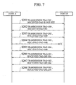
- the controller 1b of the host A 1 which transmits a packet at first acquires data from the transmission buffer 1a and creates a packet to be transmitted by using the combination of the selected IP addresses, the controller 1b adds the identification data such as a transmission tag to distinguish each packet to be transmitted, to the packet. More specifically, the controller 1b sets an identification number 201 as a transmission tag to distinguish a packet. In this case, since there are no packets transmitted from the host B 2, identification data such as a received tag to distinguish the received packet is not set. One of the reception/ transmission units 1c through 1e then transmit the packet to which a transmission tag is added and a received tag is not set, to the host B 2 (S201). In this case, the controller 1b also adds a transmission tag with identification number 201 to data used for packet creation stored in the transmission buffer 1a.
- the host B 2 After receiving a packet, the host B 2 transmits a packet to the host A 1 with the transmission tag transmitted from the host A 1 instead of transmitting an ACK signal to the host A 1. More specifically, when the controller 2b of the host B 2 acquires data from the transmission buffer 2a and creates a packet to be transmitted using the combination of the selected IP addresses, the controller 2b adds the identification data such as a transmission tag to distinguish each packet to be transmitted and the identification data such as a received tag to distinguish the packet received from the host A 1, to the packet. More specifically, the controller 2b sets an identification number 100 as the transmission tag to distinguish the packet, and the identification number 201 in the received transmission tag as the received tag.
- the reception/ transmission units 2c and 2d then transmit the packets to which a transmission tag and received tag are added, to the host A 1 (S202).
- the controller 2b also adds a transmission tag with the identification number 100 to data used for packet creation stored in the transmission buffer 2a.
- the host A 1 receives the packet, and the controller 1b confirms that the packet with the identification number 201 has been successfully transmitted and has received by the host B 2 from the added received tag. Therefore, the controller 1b searches the transmission buffer 1a based on the identification number 201, detects data used for creating the packet with the identification number 201, and deletes it from the transmission buffer 1a.
- the controller 1b when the controller 1b acquires data from the transmission buffer 1a and creates a packet to be transmitted using the combination of the selected IP addresses, the controller 1b adds the identification data, such as a transmission tag to distinguish each packet and the identification data such as a received tag to distinguish the packet received from the host B 2, to the packet. More specifically, the controller 2b sets identification numbers 202, 203, and 204 as the transmission tags, and the identification number 100 in the received transmission tag as the received tag. The reception/ transmission units 1c through 1e then transmit the packets to which transmission tags and received tag are added, to the host B 2 (S203 through S205).
- the identification data such as a transmission tag to distinguish each packet
- the identification data such as a received tag to distinguish the packet received from the host B 2
- the controller 1b also adds the transmission tags with identification numbers 202, 203, and 204 to each piece of data used for packet creation stored in the transmission buffer 1a.
- the packets transmitted in steps (S203) and (S205) have successfully received by the host B 2; the packet transmitted in step (S204) has not successfully received by the host B 2.
- the controller 2b when creating a packet to be transmitted by the controller 2b of the host B 2, the controller 2b sets the identification numbers 101, 102, and 103 to distinguish the packet as the transmission tags, and the identification numbers 202 and 204 in the received transmission tag as the received tag, respectively.
- the controller 2b does not set the identification number 203 in the transmission tag of the packet, which was not received, as the received tag.
- the reception/transmission units 2c and 2d then transmit the packets to which a transmission tag and received tag of the packet successfully received by the host B 2 are added, to the host A 1 (S206) through (S208).
- the controller 2b adds the transmission tags with identification numbers 101, 102, and 103 to data used for packet creation stored in the transmission buffer 2a.
- the controller 1b of the host A 1 confirms that the packets with the identification numbers 202 and 204 have been successfully transmitted and have received by the host B 2 from the added received tag. Therefore, the controller 1b searches the transmission buffer 1a based on the identification numbers 202 and 204, detects data used for creating the packets with the identification numbers 202 and 204, and deletes them from the transmission buffer 1a.
- the controller 1b of the host A 1 determines that the packet with the identification number 203 has not been successfully transmitted and has not received by the host B 2, based on the fact that the identification number 203 is not included in the added received tags.
- the controller 1b searches the transmission buffer 1a based on the identification number 203, and detects data used for creating the packet with the identification number 203.
- the controller 1b acquires the combination of the IP addresses of the host A 1 and the host B 2 used for transmitting the packet including the data, based on the identification data such as a tag added to the detected data.
- the controller 1b decreases the usage rate of the acquired combination of IP addresses, and increases the usage rates of other combinations of IP addresses.
- the controller 1b updates the usage rates in the table 11b according to the controlled result.
- the controller 1b controls the reception/ transmission units 1c through 1e to retransmit a packet with the identification number 203 to the host B 2.
- the reception/ transmission units 1c through 1e then retransmit the packet to the host B 2.
- the controllers 1b and 2b may explicitly recognize which packets have been successfully transmitted and received by the target equipment, and which packets have not been successfully transmitted and have not been received by the target equipment. Therefore, the usage rate of the combinations of the IP addresses for which the packets easily arrive at the target equipment and it is not necessary to retransmit packets increase, and it is possible to hasten the convergence of the usage rate to those combinations. Accordingly, the controllers 1b and 2b may control the combination of the IP addresses effectively and appropriately. In addition, the controllers 1b and 2b may confirm whether the transmission tag is successfully transmitted and the received tag corresponding to the transmission tag is transmitted or not, by receiving the received tag corresponding to the transmission tag of the transmitted packet from the target equipment. Note that the second selection method may be implemented by extending the TCP, for example.
- the present invention is also available for Ipv4 addresses and Ipv6 addresses.
- the host A 1 and the host B 2 notify all available IP addresses, however, the host A 1 and the host B2 may notify of all groups of IP addresses provided for each communication equipment initially, and subsequently, if there is a change in a group of available IP addresses, the host A 1 and the host B2 may notify only the added or deleted IP address.
Landscapes
- Engineering & Computer Science (AREA)
- Computer Security & Cryptography (AREA)
- Computer Networks & Wireless Communication (AREA)
- Signal Processing (AREA)
- Computer Hardware Design (AREA)
- Computing Systems (AREA)
- General Engineering & Computer Science (AREA)
- Data Exchanges In Wide-Area Networks (AREA)
- Small-Scale Networks (AREA)
Abstract
Description
- This application is based upon and claims the benefit of priority from the prior Japanese Patent Application No. P2002-239809, filed on August 20, 2002; the entire contents of which are incorporated herein by reference.
- The present invention relates to a communication equipment, a communication system, and a communication method.
- Conventionally, a communication equipment that performs packet communication using an Internet protocol (IP) address uses one IP address for each communication. A communication procedure to be performed by a communication equipment to which an IP address is provided, respectively, is described as taking a host A and host B as an example. The host A sets its own IP address as the source address, and transmits to the host B a packet where an IP address of the host B is set as the destination address to start communication. After receiving the transmitted packet, the host B sets the source address included in the received packet as the destination address of the packet, and sets the destination address included in the received packet as the source address of the packet, and then transmits the packet to the host A. Through repetition of this procedure, the host A and host B communicate. Note that the route for packet reception/ transmission is determined by routers that exist between the communication equipments, based on the source address or destination address of each packet.
- In addition, an IP address is, normally, provided for each media in an IP network. For example, a local area network (LAN) forms one media, and an IP address is provided for each LAN. This is similar to the case of a wireless LAN, which has become more prevalent in recent years. The wireless LAN is an area network where a base station is connected to a fixed LAN, and where a mobile communication equipment having a wireless LAN card performs wireless communication with a LAN by connecting to the base station.
- However, conventionally, a communication equipment can use only one IP address for each communication. As a result, a packet reception/ transmission route determined by a router based on a source address or a destination address of a packet is almost always fixed to one route even though there may be a plurality of routes between communication equipments. Accordingly, a communication equipment cannot perform packet reception/ transmission using a more preferable route or packet reception/ transmission using a plurality of routes. As a result, effective data transfer cannot be performed.
- In addition, if a srperate IP address is provided within each LAN, a communication equipment cannot use an IP address that is provided within one LAN, within another LAN. In a wireless LAN, the same IP address can be used if the communication equipment exists within the same wireless LAN area even if the communication equipment moves and changes the base station connection. However, in the case where the communication equipment moves outside the wireless LAN area, even if the communication equipment can find and connect to a new base station, the new base station connects to a wireless LAN, which is different from the previously connected wireless LAN. As a result, the communication equipment becomes unable to use the IP address provided for the previously connected wireless LAN.
- Accordingly, the communication equipment must acquire a new IP address that can be used with the newly connected wireless LAN. Also, there is a problem in that the communication equipment cannot maintain prior communication. That is, the communication equipment cannot guarantee continuous mobile communication. Mobile IP has been proposed as a technology for solving such problems. However, a specific function for using Mobile IP must be provided for the IP network in advance.
- An object of the present invention is to provide a communication equipment, a communication system, and a communication method, which can perform effective data transfer and mobile communication.
- A communication system of the present invention comprises a communication equipment provided with a plurality of addresses, and a target equipment provided with a plurality of target equipment addresses, and configured to perform packet reception/ transmission from/ to the communication equipment. The communication equipment of the present invention comprises a reception/ transmission unit configured to notify the target equipment of a plurality of provided addresses, acquire a plurality of target equipment addresses, from the target equipment, and perform packet reception/ transmission using the plurality of provided addresses and the plurality of acquired target equipment addresses; and a controller configured to select the target equipment address to be used by the reception/transmission unit, and control the reception/ transmission unit to perform the packet reception/ transmission using a selected target equipment address. Note that the target equipment is a target communication equipment for performing packet reception/ transmission. The target equipment address is an address provided for the target equipment.
- According to the communication system or the communication equipment of the present invention, a plurality of addresses is provided for the communication equipment. The reception/ transmission unit notifies the target equipment, which is the target for communication, of the plurality of addresses. In addition, the reception/ transmission unit acquires the plurality of target equipment addresses. The reception/ transmission unit then performs packet reception/transmission using the plurality of addresses provided for the communication equipment and the plurality of acquired target equipment addresses. Furthermore, the controller selects the target equipment address to be used by the reception/transmission unit and controls the reception/ transmission unit to perform packet reception/ transmission using it.
- Accordingly, the communication equipment may perform packet reception/ transmission via a plurality of routes by using a plurality of addresses provided for itself and the plurality of target equipment addresses. As a result, the communication equipment may perform high-speed data transfer, that is, the communication equipment may perform more effective data transfer. Furthermore, if the communication equipment moves, the communication equipment may use a plurality of addresses provided for itself even when it moves between different networks. Therefore, the communication equipment does not require the acquisition of a new address, and it may continue communication. In addition, if the target equipment moves, the communication equipment may use the plurality of target equipment addresses even when the target equipment moves between different networks. Therefore, the communication equipment may continue to maintain prior communication. Accordingly, the communication equipment may guarantee continuous mobile communication.
- A communication method of the present invention comprises notifying a target equipment of a plurality of addresses provided for a communication equipment, acquiring a plurality of target equipment addresses provided for the target equipment, selecting the target equipment address to be used for packet reception/ transmission, and performing the packet reception/transmission using the plurality of addresses provided for the communication equipment and a selected target equipment addresses.
- According to the communication method of the present invention, the communication equipment may perform packet reception/ transmission via the plurality of routes by using a plurality of addresses provided for itself and the plurality of target equipment addresses. As a result, the communication equipment may perform high-speed data transfer, that is, may perform more effective data transfer. Furthermore, if the communication equipment moves, the communication equipment may use the plurality of addresses provided for itself even when it moves between different networks. Therefore, the communication equipment does not require acquiring a new address, and it may continue communication. In addition, if the target equipment moves, the communication equipment may use the plurality of target equipment addresses even when the target equipment moves between different networks. Therefore, the communication equipment may continue to maintain prior communication. Accordingly, the communication equipment may guarantee continuous mobile communication.
-
- FIG. 1 is a block diagram illustrating a configuration of a communication system according to an embodiment of the present invention;
- FIG. 2 is a diagram illustrating a state where a plurality of routes exists according to an embodiment of the present invention;
- FIG. 3 is a diagram for describing a first selection method for selecting a combination of addresses according to an embodiment of the present invention;
- FIG. 4A and FIG. 4B are diagrams for describing a second selection method for selecting a combination of addresses according to an embodiment of the present invention;
- FIG. 5 is a diagram illustrating mobile communication according to an embodiment of the present invention;
- FIG. 6 is a flowchart illustrating a procedure of a communication method according to an embodiment of the present invention; and
- FIG. 7 is a sequence diagram illustrating a procedure of a second selection method for selecting a combination of addresses according to a modified example of the present invention.
-
- As shown in FIG. 1, a communication system comprises a
host A 1, ahost B 2, and a domain name system (DNS) server 3. Thehost A 1 and thehost B 2 exist in different networks. Thehost A 1, thehost B 2, and the DNS server 3 are connected via a network. Thehost A 1 and the host B2 are communication equipments, such as a terminal equipment or a server that perform packet reception/ transmission. Thehost B 2 is a target equipment for performing packet reception/ transmission in view of the host A1; and thehost A 1 is a target equipment in view of thehost B 2. In FIG. 1, only two hosts are illustrated in order to simplify the explanation, however, there are more hosts in the communication system. - A plurality of IP addresses is provided for the
host A 1 and thehost B 2, respectively. Hereafter, a plurality of IP addresses is called "a group of IP addresses" when they are referred to collectively. IP addresses may be provided manually when setting up thehost A 1 or the host B2, for example. In addition, IP addresses may be provided through a dynamic host configuration protocol (DHCP) when thehost A 1 or thehost B 2 is activated. IP addresses may also be provided through a point to point protocol (PPP) when thehost A 1 orhost B 2 connects to the network by a dial up connection, or the like. Note that an IP address is managed and provided by an Internet service provider (ISP), for example. Thehost A 1 and thehost B 2 may connect to the network managed by a plurality of Internet service providers in order to acquire IP addresses managed by respective Internet service providers. The IP addresses of thehost B 2 are target equipment addresses for thehost A 1; and the IP addresses of thehost A 1 are target equipment addresses for thehost B 2. - The
host A 1 and thehost B 2 associate the plurality of provided IP addresses with domain names, and register them in the DNS server 3. When an IP address is changed, thehost A 1 and thehost B 2 update the IP addresses registered in the DNS server 3 and register the latest IP address by using a dynamic DNS (see request for comments (RFC) 2136). Note that a plurality of IP addresses and domain names may be registered manually in the DNS server 3 when thehost A 1 or thehost B 2 is set up. - The DNS server 3 associates and stores a plurality of IP addresses provided for the
host A 1 and for thehost B 2 with the domain names of thehost A 1 and thehost B 2, respectively. As shown in FIG. 1, the DNS server 3 associates and stores the domain name of thehost A 1 "hostA.our.jp" with a plurality of IP addresses provided for thehost A 1 "220.220.1.1, 230.221.1.1, and 240.222.1.1". In addition, the DNS server 3 associates and stores the domain name of thehost B 2 "hostB.you.jp" with a plurality of IP addresses provided for thehost B 2 "220.240.2.2 and 220.240.1.1". - The
host A 1 and thehost B 2comprise transmission buffers 1a and 2a,controllers transmission units 1c through 1e and 2c and 2d, respectively. The reception/transmission units 1c through 1e, 2c, and 2d perform packet reception/ transmission. An IP address is provided for each of the reception/transmission units 1c through 1e, 2c, and 2d, respectively. More specifically, one of the plurality of IP addresses provided for thehost A 1 is provided for each of the reception/transmission units 1c through 1e, respectively. Similarly, one of the plurality of IP addresses provided for thehost B 2 is provided for each of the reception/transmission units - The reception/
transmission units 1c through 1e notify thehost B 2, of a plurality of IP addresses provided for thehost A 1. Then, the reception/transmission units host A 1 as the target equipment addresses, from thehost A 1, which is the target equipment. Similarly, the reception/transmission units host A 1, of a plurality IP addresses provided for thehost B 2. Then, the reception/transmission units 1c through 1e acquire a plurality of IP addresses provided for thehost B 2 as the target equipment addresses, from thehost B 2, which is the target equipment. - The
controllers transmission units 1c through 1e and 2c and 2d, respectively. More specifically, thecontrollers transmission units 1c through 1e and 2c and 2d, and control the reception/transmission units 1c through 1e and 2c and 2d to perform packet reception/ transmission using the selected target equipment addresses, respectively. In addition, thecontrollers host A 1 and thehost B 2, respectively. - To begin with, an operation is described wherein upon starting communication, the
host A 1 and thehost B 2 notify the target equipment of a plurality of IP addresses provided for themselves, respectively, and acquire from the target equipment a plurality of IP addresses provided for the target equipment. Here, a case where thehost A 1 attempts to start communication is described as an example. - To begin with, before starting communication, the
controller 1b of thehost A 1 instructs the reception/transmission units 1c through 1e to inquire after a group of IP addresses of thehost B 2 from the DNS server 3, using the domain name of thehost B 2 as a key. Note that thecontroller 1b stores the domain name of thehost B 2 through manual setting or the like. The reception/transmission units 1c through 1e transmit inquiry packets to the DNS server 3. The DNS server 3 transmits packets including a group of IP addresses of thehost B 2 to the reception/transmission units 1c through 1e. Thecontroller 1b acquires a group of IP addresses of thehost B 2 from the packet received by the reception/transmission units 1c through 1e. Thecontroller 1b creates a notification packet including a group of available IP addresses provided for thehost A 1, in order to start communication. Thecontroller 1b sets one of the IP addresses included in the acquired group of IP addresses of thehost B 2, as a destination address of the notification packet. Thecontroller 1b inputs a created notification packet to one of the reception/transmission units 1c through 1e. One of the reception/transmission units 1c through 1e transmits the notification packet to thehost B 2 to notify thehost B 2, of a group of available IP addresses provided for thehost A 1. - The reception/
transmission unit host B 2 to which the destination address of the notification packet is provided receives the notification packet and acquires a group of available IP addresses provided for thehost A 1. The reception/transmission unit controller 2b. Thecontroller 2b acquires a group of available IP addresses provided for thehost A 1 from the notification packet. Subsequently, thecontroller 2b recognizes that all the packets where addresses of the acquired group of IP addresses, provided for thehost A 1 are set as the source addresses, are the ones transmitted from thehost A 1. - The
controller 2b creates a response packet corresponding to the notification packet for starting communication. Thecontroller 2b creates the response packet including a group of available IP addresses provided for thehost B 2. Thecontroller 2b sets the destination address of the notification packet received from thehost A 1 as a source address. Thecontroller 2b sets one of the IP addresses included in the acquired group of IP addresses of thehost A 1 as a destination address of the response packet. Thecontroller 2b inputs the created response packet to the reception/transmission unit transmission unit host A 1 to notify of a group of available IP addresses provided for thehost B 2. - One of the reception/
transmission units 1c through 1e of thehost A 1 to which the destination address of the response packet is provided receives the response packet, and acquires a group of available IP addresses provided for the host B2 . One of the reception/transmission units 1c through 1e then inputs the received response packet to thecontroller 1b. Thecontroller 1b acquires a group of available IP addresses provided for thehost B 2 from the response packet. Subsequently, thecontroller 1b recognizes that all the packets where addresses of the acquired group of IP addresses, provided for thehost B 2 are set as the source addresses, are the ones transmitted from thehost B 2 . Note that thehost A 1 recognizes a group of IP addresses included in the response packet from thehost B 2, as a group of IP addresses of thehost B 2, since the available IP addresses may be changed, although a group of IP addresses of thehost B 2 is acquired from the DNS server 3. In this manner, thehost A 1 and thehost B 2 notify the target equipment of a plurality of available IP addresses provided for themselves, acquire a plurality of available IP addresses provided for the target equipment from the target equipment, and then communication is started. - The
controllers controllers controllers - Furthermore, the
host A 1 and thehost B 2 notify the target equipment of a group of available IP addresses, and acquire a group of available IP addresses from the target equipment not only when starting communication but also in the case where a group of available IP addresses has changed. There is an addition case of a group of IP addresses, such as providing a new IP address for thehost A 1 or for thehost B 2, or becoming available from an unavailable IP address. There is a deletion case of a group of IP addresses, such as becoming unavailable from an available IP address provided for thehost A 1 or for thehost B 2. In addition, thehost A 1 and thehost B 2 may regularly notify the target equipment of a group of IP addresses and acquire a group of IP addresses from the target equipment, in order to confirm a group of available IP addresses. - For example, in the addition case, such as providing a new IP address for the
host A 1, or becoming available from an unavailable IP address, thecontroller 1b creates an notification packet including the added IP address. One of the reception/transmission units 1c through 1e then transmit the notification packet to thehost B 2 in order to notify of a group of available IP addresses provided for thehost A 1 including the added IP address. The reception/transmission unit host B 2 receives the notification packet and acquires a group of available IP addresses provided for thehost A 1 including the added IP address. The reception/transmission unit controller 2b. Thecontroller 2b acquires the added IP address , and subsequently recognizes that the packet where the added IP address is set as the source address is also a packet transmitted from thehost A 1. Thecontroller 2b creates an acknowledgement packet where the added IP address is set as a destination address. The reception/transmission unit host A 1. Through reception of the confirmation packet, thecontroller 1b of thehost A 1 may confirm that thehost B 2 has acknowledged the added packet. - Meanwhile, when the IP address provided for the
host B 2 becomes unavailable and is deleted, for example, thecontroller 2b creates a notification packet where the deleted IP address is not included. The reception/transmission unit host A 1 in order to notify of a group of currently available IP addresses provided for thehost B 2 where the deleted IP address is not included. One of the reception/transmission units 1c through 1e of thehost A 1 receive the notification packet and acquires a group of currently available IP addresses provided for thehost B 2 where the deleted IP address is not included. One of the reception/transmission units 1c through 1e inputs the received notification packet to thecontroller 1b Thecontroller 1b may recognize that the IP address is deleted through acquiring a group of IP addresses where the deleted IP address is not included. In this manner, thehost B 2 may implicitly notify thehost A 1, of the deletion of available IP address. Note that when an IP address is deleted, as the addition case, thehost A 1 may transmit a packet, in order to notify thehost B 2 , of recognition the deletion of the IP address , however, it is not always necessary to transmit the packet, since a packet destined for the deleted IP address is not transferred to thehost B 2, and the unavailable address becomes gradually unused. - With the above-described method, the
host A 1 and thehost B 2 notify the target equipment of a plurality of available IP addresses provided for themselves, acquire a plurality of available IP addresses provided for the target equipment from the target equipment, and then start communication. A case where thehost A 1 transmits data and thehost B 2 receives data is described as an example. Thecontroller 1b of thehost A 1 acquires data from the transmission buffer 1a to create a packet. Thecontroller 1b selects an IP address to be used by the reception/transmission units 1c through 1e from the acquired group of IP addresses of thehost B 2, and sets the selected IP address as a destination address. Thecontroller 1b also selects one of the reception/transmission units 1c through 1e, which transmits the packet, and sets the IP address provided for the selected one of the reception/transmission units 1c through 1e, as a source address. Thecontroller 1b inputs a created packet to the selected one of the reception/transmission units 1c through 1e. One of the reception/transmission units 1c through 1e then transmits the packet. - The reception/
transmission unit host B 2 receives the packet transmitted from thehost A 1. The reception/transmission unit controller 2b. Thecontroller 2b checks the source address of the received packet with the acquired group of IP addresses of thehost A 1. When the source address of the received packet is included in the group of IP addresses of thehost A 1, thecontroller 2b recognizes that the packet is a packet transmitted from thehost A 1. Note that the packet reception/transmission in the case where thehost B 2 transmits data and thehost A 1 receives data may be performed in the same manner. - As shown in FIG. 2, a
network 4 where thehost A 1 exists and a network 5 where thehost B 2 exists are connected via a plurality ofnetworks first route 7 via thenetwork 6a and asecond route 8 via thenetwork 6b, between thehost A 1 and thehost B 2. Therefore, thecontrollers transmission units 1c through 1e and 2c and 2d, respectively. And, thecontrollers transmission units 1c through 1e, 2c, and 2e to perform packet reception/transmission in parallel via a plurality of routes . A plurality of reception/transmission units 1c through 1e, 2c, and 2d then transmit the packet input from thecontrollers - Note that the
controllers host A 1 and thehost B 2. When another host receives the encrypted packet, the host discards the packet since the host cannot decrypt the data. Therefore, the communication of that host is not be affected. More preferably, thecontrollers transmission units 1c through 1e, 2c, and 2d to reject the reception of unencrypted packets. By this communication affected by another hosts can be prevented. - The
controllers controllers controllers transmission units 1c through 1e, 2c, and 2d, from the combinations. Then thecontrollers transmission units 1c through 1e, 2c, and 2d to perform packet reception/ transmission by using the selected combinations. As described above, there are a plurality of routes between thehost A 1 and thehost B 2. Therefore, thecontrollers host A 1 and thehost B 2. - A first selection method for selecting the combination of the addresses is described by using FIG. 3. In FIG. 3, for simplifying the explanation, components not needed for explanation in the first selection method are omitted, and IP addresses are indicated with two-digit numbers. The
host A 1 and thehost B 2 are connected via thenetwork 6. There are a plurality of routes via thenetwork 6 between thehost A 1 and thehost B 2. IP addresses "10", "11", and "12" are provided for the reception/transmission units 1c through 1d of thehost A 1, respectively. IP addresses "21" and "22" are provided for the reception/transmission units host B 2, respectively. In this case, there are 3 × 2 = 6 kinds of combinations of the IP addresses for thehost A 1 and for thehost B 2. - The first selection method is described by taking the operation of the
host A 1 as an example. Thecontroller 1b of thehost A 1 selects the combinations of the IP addresses of thehost A 1 and the IP addresses of thehost B 2 for respective reception/transmission units 1c through 1e from the six kinds of combinations. Thecontroller 1b then instructs the respective reception/transmission units 1c through 1e to connect the TCP connection to the IP address of thehost B 2 included in the selected combination, and perform packet reception/ transmission. The reception/transmission units 1c through 1e connect the TCP connection and perform packet reception/ transmission according to the instruction. Thecontroller 1b monitors the state where the reception/transmission units 1c through 1e perform packet reception/transmission from/ to thehost B 2, and measures the packet transmission efficiency. Thecontroller 1b may measure the transmission efficiency through the TCP. - The
controller 1b determines disconnection of the TCP connection and abortion of the communication of the combinations for which the packet transmission efficiency is low. Thecontroller 1b then instructs the reception/transmission units 1c through 1e, which connect the determined connection to disconnect the TCP connection and abort the communication. For example, thecontroller 1b monitors the state of the packet reception/ transmission, and determines disconnection of the TCP connection of the combinations where the transmission efficiency is less than the prescribed transmission efficiency threshold. The reception/transmission units 1c through 1e disconnect the TCP connection and abort communication, according to the instruction from thecontroller 1b. Note that the TCP connection of the combinations where the packet transmission efficiency is high are not disconnected and communication of these combinations continue. - The
controller 1b then selects the combination of the IP addresses of thehost A 1 and the IP addresses of thehost B 2 that has not yet been selected for the reception/transmission units 1c through 1e where communication has been aborted. Thecontroller 1b then instructs the respective reception/transmission units 1c through 1e to re-connect the TCP connection to the IP address of thehost B 2 included in the selected combination, and perform packet reception/transmission. Subsequently, as in the above, thehost A 1 performs packet reception/ transmission, monitors the state, disconnects the TCP connection where the packet transmission efficiency is low, and selects other combinations. The host A may continue packet reception/ transmission while giving priority to the combination of the IP addresses of thehost A 1 and the IP addresses of thehost B 2 having high transmission efficiency, through repetition of such sequential operations. Note that thehost B 2 may perform packet reception/transmission by selecting the most appropriate combination of IP addresses of thehost A 1 and the IP addresses of thehost B 2, in the same manner. - Next, a second selection method for selecting combinations of the IP addresses is described by using FIGS. 4A and 4B. In FIGS. 4A and 4B, for simplifying the explanation, components not needed for explanation of the second selection method are omitted, and IP addresses are indicated with two-digit numbers. The second selection method is described taking the operation of the
host A 1 as an example. Thecontroller 1b of thehost A 1 stores rates of all the combinations of the IP addresses of thehost A 1 and the IP addresses of thehost B 2 which are used for packet reception/ transmission (hereafter, referred to as "usage rate"). More specifically, thecontroller 1b comprises a table 11b shown in FIG. 4B. - In table 11b, combinations of the IP addresses of the
host A 1 and the IP addresses of thehost B 2, and usage rates are stored while relating each other. Note that in the table 11b of thecontroller 1b of thehost A 1, combinations of the IP addresses of thehost A 1 and the IP addresses of thehost B 2 are set on the basis of the IP addresses of thehost A 1, such as "10 → 20", "10 → 21", "11 → 20", "11 → 21", "12 → 20", and "12 → 21". Similarly, in the table of thecontroller 2b of thehost B 2, the combinations of the IP addresses of thehost A 1 and the IP addresses of thehost B 2 are set on the basis of the IP addresses of thehost B 2. Table 11b shown in FIG. 4B indicates the initial state. In the initial state, the usage rates of all combinations are set to 16.6% equivalently. - The
controller 1b selects a combination of IP addresses of thehost A 1 and the IP addresses of thehost B 2 to be used for packet reception/ transmission to attain the same usage rates, as stored in the table 11b, when thehost A 1 performs the packet reception/ transmission. Thecontroller 1b may select a combination of IP addresses of thehost A 1 and the IP addresses of thehost B 2 by using random numbers , for example. Thecontroller 1b then acquires data from the transmission buffer 1a, and creates a packet to be transmitted by using the selected combination of IP addresses. Thecontroller 1b adds identification data such as a tag which indicates the combination of IP addresses of thehost A 1 and the IP addresses of thehost B 2 to be used for transmitting the created packet, to the data used for packet creation and stored in the transmission buffer 1a. In other words, thecontroller 1b adds the identification data such as a tag, which indicates the combination of IP addresses of the packet transmitted, to the data used for packet creation in the transmission buffer 1a. - The
controller 1b inputs the created packet to the reception/transmission units 1c through 1e, which is provided with the IP addresses of thehost A 1 included in the selected combination. The reception/transmission units 1c through 1e transmit apacket 9a to thehost B 2. The reception/transmission unit host B 2 included in the selected combination receives thepacket 9a, and transmits an acknowledgement signal (ACK signal) 9b to thehost A 1, in response to thepacket 9a. - The reception/
transmission unit 1c through 1e receives theACK signal 9b transmitted from thehost B 2, and then inputs it to thecontroller 1b When the ACK signal is input, thecontroller 1b may confirm that the packet corresponding to the ACK signal has been successfully transmitted and received by thehost B 2 . As a result, thecontroller 1b detects and deletes the data used for creating the packet corresponding to the ACK signal, from the transmission buffer 1a. - Meanwhile, if the ACK signal is not input from the reception/
transmission unit 1c through 1e to thecontroller 1b after a prescribed period has elapsed, the time for confirming the result of the packet transmission ends . In other words, time-out of transmission confirmation occurs. In this case, thecontroller 1b retrieves the transmission buffer 1a, and detects the data used for creating the packet, which was transmitted following the packet corresponding to the finally received ACK signal. Thecontroller 1b determines that the packet including detected data did not successfully arrive at thehost B 2. Thecontroller 1b then acquires the combination of the IP addresses of thehost A 1 and the IP addresses of thehost B 2 used for transmitting the packet including the data, based on the identification data such as a tag added to the detected data. - The
controller 1b decreases the usage rate of the acquired combination of the IP addresses, and increases the usage rates of other combinations of the IP addresses. For example, thecontroller 1b divides the decreased usage rate by the number of other combinations, and adds the quotient to all other usage rates of the combinations evenly. Thecontroller 1b updates the usage rate in the table 11b according to the controlled result. Since thecontroller 1b selects a combination of the IP addresses by using the usage rate stored in the table 11b when transmitting a packet, the usage rate updated in this manner is used for selecting a combination of the IP addresses. In addition, thecontroller 1b controls the reception/transmission units 1c through 1e to retransmit a packet including the detected data to thehost B 2. The reception/transmission units 1c through 1e then retransmits the packet to thehost B 2. - The
host A 1 may increase the usage rate of the combinations of IP addresses of thehost A 1 and the IP addresses of thehost B 2 where the packet may easily arrive at thehost B 2, and retransmission is not required, through repetition of such sequential operations . As a result, the host A may perform packet reception/ transmission by using a combination of IP addresses of thehost A 1 and the IP addresses of thehost B 2 where the packet may easily arrive at thehost B 2. In other words, thehost A 1 may perform packet reception/ transmission by using a route where the packet may easily arrive at thehost B 2, and retransmission is not required. Accordingly, thehost A 1 may improve the packet transmission efficiency. Note that thehost B 2 may perform packet reception/ transmission by selecting the most appropriate combination of the IP addresses of thehost A 1 and the IP addresses of thehost B 2, in the same manner. Note that the second selection method may be implemented by extending the TCP, for example. - Note that in FIG. 4B, all usage rates of the combinations are set to the equivalent value in the initial state. However, the usage rate in the initial state may be set to other values. For example, the packet transmission rate may be different for each route determined by a combination of IP addresses of the
host A 1 and IP addresses of thehost B 2. In this case, the usage rate in the initial state are preferably set in proportion to the transmission rate of each route determined by a combination of IP addresses of thehost A 1 and the IP addresses of thehost B 2. - For example, since IP addresses are provided for the reception/
transmission units 1c through 1e, 2c, and 2d, respectively, thecontroller 1b of thehost A 1 creates a packet where the transmission rate for respective reception/transmission units 1c through 1e relative to the total transmission rate of all reception/transmission units 1c through 1e corresponds to the IP addresses provided for respective reception/transmission units 1c through 1e. One of the reception/transmission units 1c through 1e then transmit the packet to thehost B 2. Thecontroller 2b of thehost B 2 creates a similar packet, and One of the reception/transmission units controllers host A 1 and the IP addresses of thehost B 2, and may use the result as the initial values of the usage rates. - More specifically, the
controller 1b calculates a product of the transmission rates of respective reception/transmission units 1c through 1e relative to the total transmission rate of all reception/transmission units 1c through 1e of thehost A 1, and the transmission rate of respective reception/transmission units transmission units host B 2 transmitted from thehost B 2, as an initial value of the usage rate for every combination of the IP addresses of thehost A 1 and the IP addresses for thehost B 2. Similarly, thecontroller 2b calculates products of the transmission rates of respective reception/transmission units transmission units host B 2 and the transmission rates of respective reception/transmission units 1c through 1e relative to the total transmission rate of all reception/transmission units 1c through 1e of thehost A 1 transmitted from thehost A 1, as an initial value of the usage for every combination of the IP addresses of thehost A 1 and the IP addresses of thehost B 2. - Note that initial values of the usage rates may be set by using the transmission rate of the network where each route determined by a combination of the addresses of the
host A 1 and the addresses of thehost B 2 exists, other than the transmission rate of the reception/transmission units 1c through 1e, 2c, and 2d. In this case, even if the maximum transmission rate of a wireless LAN is 11 Mbps, the effective transmission rate may be lower, for example, 2 Mbps . Therefore, the initial value of the usage rate is preferably set, by using the effective transmission rate of every network. - In this manner, when the usage rate in the initial state is set in proportion to the transmission rate of each route determined by a combination of the IP addresses of the
host A 1 and the IP addresses of thehost B 2, the usage rate of the combination of the IP addresses of thehost A 1 and the IP addresses of thehost B 2 with higher transmission rate and suitability for usage may increase. Accordingly, the hosts A 1 andB 2 may perform packet reception/ transmission using a combination of the addresses with higher transmission rates and higher transmission efficiency. More specifically, when the initial value is set by using the transmission rate of each reception/ transmission unit relative to the total transmission rate of all reception/ transmission units, thehost A 1 and thehost B 2 may use the reception/ transmission unit with the higher transmission rate. - A case where the
host A 1 is mobile is described using FIG. 5. In FIG. 5, a plurality ofbase stations 41a constitutes anetwork 4a; and a plurality ofbase stations 41b configures anetwork 4b. Initially, thehost A 1 exists in thenetwork 4a. Thehost A 1 connects to thebase station 41a to connect to thenetwork 4a, and performs packet reception/ transmission from/ to thehost B 2. In this case, thecontroller 1b of thehost A 1 creates a notification packet including the IP addresses available in thenetwork 4a, from a plurality of IP addresses provided for thehost A 1. And thecontroller 1b instructs one of the reception/transmission units 1c through 1e to notify thehost B 2. In addition, thecontroller 1b instructs the reception/transmission units 1c though 1e to which the IP addresses available in thenetwork 4a are provided to perform packet reception/ transmission. - The reception/
transmission unit host B 2 receives the notification packet, and thecontroller 2b acquires the IP address available for packet reception/transmission from/ to thehost A 1 existing in thenetwork 4a. Thecontroller 2b creates a response packet including a group of available IP addresses provided for thehost B 2, and inputs the created response packet to either reception/transmission unit transmission unit host A 1. Subsequently, thecontroller 2b selects the IP address available for communication with thehost A 1, and available for thehost A 1 in thenetwork 4a, as the IP address to be used for packet reception/ transmission. Thecontroller 2b instructs the reception/transmission units transmission units 1c through 1e provided with the IP addresses available in thenetwork 4a and reception/transmission units connection 10a, and perform packet reception/transmission. - When the
host A 1 moves and arrives in the vicinity of the boundary between thenetwork 4a and thenetwork 4b, thehost A 1 becomes able to receive both radio waves from thebase stations 41a and thebase station 41b, and to use both radio waves. In this case, thehost A 1 connects to thebase station 41b to connect to thenetwork 4b while maintaining connection with thebase stations 41a. Therefore, thehost A 1 may use the IP addresses available in thenetwork 4b in addition to the IP addresses available in thenetwork 4a. - The
controller 1b for thehost A 1 creates a notification packet including the IP address available in thenetwork 4a and the IP address available in thenetwork 4b, which are added to the available IP addresses. Thecontroller 1b instructs one of the reception/transmission units 1c through 1e to transmit the notification packet to thehost B 2. In addition, thecontroller 1b instructs the reception/transmission units 1c through 1e provided with the IP addresses available in thenetwork 4a and the reception/transmission units 1c through 1e provided with the IP addresses available in thenetwork 4b, to perform packet reception/ transmission. In this manner, thecontroller 1b controls them so that a plurality of reception/transmission units 1c through 1e performs packet reception/transmission in parallel. - The
controller 2b may learn that the IP addresses available in thenetwork 4b become available, in addition to the IP addresses available in thenetwork 4a, when the reception/transmission units host B 2 receive the notification packet. Thecontroller 2b selects a plurality of IP addresses, which are available for thehost A 1 both in thenetwork 4a and thenetwork 4b, as the target equipment address available for communication with thehost A 1. Thecontroller 2b instructs the reception/transmission units transmission units 1c through 1e and reception/transmission units network 4b then connect anew connection 10b, in addition to theconnection 10a, and perform packet reception/transmission. As a result, thehost A 1 and thehost B 2 may perform packet reception/ transmission using two routes at the same time. Accordingly, thehost A 1 may perform high-speed data transfer, that is, may perform more effective data transfer by using a plurality of routes. - Meanwhile, when the
host A 1 moves, and arrives at a position where only radio waves ofbase stations 41b in thenetwork 4b may be received, from thenetwork 4a, the addresses available in thenetwork 4a become unavailable in thenetwork 4b. Thecontroller 1b of thehost A 1 creates an notification packet, which the IP addresses available in thenetwork 4a, which become unavailable are not included, but the IP addresses available in thenetwork 4b only, are included. Thecontroller 1b instructs the reception/transmission units 1c through 1e to transmit the notification packet to thehost B 2. In addition, thecontroller 1b instructs the reception/transmission units 1c through 1e provided with the IP addresses available in thenetwork 4a, to abort packet reception/ transmission, and the reception/transmission units 1c through 1e provided with the IP addresses available in thenetwork 4b, to perform packet reception/ transmission. In this manner, thecontroller 1b switches the reception/ transmission unit to perform packet reception/ transmission. - When the reception/
transmission units host B 2 receive the notification packet, thecontroller 2b may learn that the IP addresses available in thenetwork 4a have become unavailable, and that the IP addresses available in thenetwork 4b have become available. Thecontroller 2b then selects the IP address available for communication with thehost A 1, and available for thehost A 1 in thenetwork 4b as the IP address to be used for reception/ transmission from/ to thehost A 1. Thecontroller 2b instructs the reception/transmission units transmission units 1c through 1e and the reception/transmission units network 4a then disconnect theconnection 10a. In addition, the reception/transmission units 1c through 1e and reception/transmission units network 4b connect thenew connection 10b with thehost B 2, and perform packet reception/ transmission. In other words, thehost A 1 and thehost B 2 may easily continue the communication between thehost A 1 and thehost B 2 that has been performed up until now, by switching theconnection 10a to theconnection 10b. Note that thehost A 1 and thehost B 2 may similarly perform the packet reception/ transmission, even in the case where thehost B 2 moves or in the case where bothhost A 1 and thehost B 2 move. - Next, a communication method using such a communication system is described. As shown in FIG. 6, to begin with, the
host A 1 inquires after a group of IP addresses of thehost B 2 from the DNS server 3, using the domain name of thehost B 2 as a key, and acquires a group of IP addresses of thehost B 2, before starting communication. Initially, two IP addresses, 220.220.1.1 and 230.221.1.1 are provided for the host A1, and those are available (S101). Thehost A 1 creates an notification packet including a group of available IP addresses provided for thehost A 1, "220.220.1.1, and 230.221.1.1", and sets one IP address included in the acquired group of IP addresses of thehost B 2 as a destination address of the notification packet. Thehost A 1 then transmits the notification packet to thehost B 2 to notify thehost B 2 of the group of IP addresses available for the host A 1 (S102). Thehost B 2 that has received the notification packet acquires a group of available IP addresses provided for thehost A 1 from the notification packet. Subsequently, thehost B 2 recognizes that all the packets where addresses of acquired group of IP addresses, provided for thehost A 1 are set as the destination address are the ones transmitted from thehost A 1. - Meanwhile, two IP addresses, 220.240.2.2 and 220.240.1.1 are provided for the
host B 2, and those are available (S103). Thehost B 2 creates a response packet including a group of available IP addresses provided for thehost B 2, "220.240.2.2, and 220.240.1.1" in response to the notification packet from thehost A 1, and sets the source address of the notification packet as a destination address of the response packet. Thehost B 2 then transmits the response packet to thehost A 1 to notify thehost A 1 of the group of IP addresses available for the host B 2 (S104). Thehost A 1 that has received the response packet acquires a group of available IP addresses provided for thehost B 2 from the response packet. Subsequently, thehost A 1 recognizes that all packets where addresses of the acquired group of IP addresses, provided for thehost B 2 are set as the source address are the ones transmitted from thehost B 2. - In this manner, the
host A 1 and thehost B 2 notify the target equipment of a plurality of IP addresses provided for themselves, and acquire a plurality of IP addresses provided for the target equipment from the target equipment. Then thehost A 1 transmits a packet to thehost B 2 using the IP address of thehost A 1 and the IP address of the host B 2 (S105). Thehost B 2 transmits a packet to thehost A 1 using the IP address of thehost B 2 and the IP address of the host A 1 (S106). Such packet reception/ transmission is repeated (S107, S108). - When a new IP address 240.222.1.1 becomes available for the
host A 1 during the packet reception/ transmission (S109), thehost A 1 transmits to thehost B 2 a notification packet including the IP address 240.222.1.1 which newly becomes available, and the IP addresses 220.220.1.1 and 230.221.1.1 which have been available, in order to notify of a group of available IP addresses (S110). Thehost B 2 that has received the notification packet acquires the IP address of thehost A 1 newly added. - Subsequently, the
host B 2 transmits a packet to thehost A 1 also using the IP address of thehost A 1 newly added (S111). In addition, thehost A 1 transmits a packet to thehost B 2 also using the IP address for thehost A 1 newly added (S112). When the IP address 220.240.1.1 used by thehost B 2 becomes unavailable during the packet reception/ transmission (S113), thehost B 2 transmits to the host A 1 a notification packet in which the unavailable IP address , 220.240.1.1 is not included, and only the currently available IP address 220.240.2.2, is included, in order to notify thehost A 1 of the available IP address (S114). Thehost A 1 that has received the notification packet recognizes that the IP address 220.240.1.1 has become unavailable. - Subsequently, the
host A 1 transmits a packet to thehost B 2 using the only IP address of thehost B 2 which is currently available (S115). In addition, thehost B 2 transmits a packet to thehost A 1 using the only IP address of thehost B 2 which is currently available (S116). Such packet reception/transmission is repeated (S117). - According to the communication system,
host A 1,host B 2, and the communication method, a plurality of IP addresses are provided for thehost A 1 and thehost B 2 . And, the reception/transmission units 1c through 1e and 2c and 2d notify thehost B 2 or thehost A 1, which is target equipment to perform communication with each other, of a plurality of IP addresses, respectively. In addition, the reception/transmission units 1c through 1e, 2c, and 2d receive and acquire a plurality of addresses of the target equipment. The reception/transmission units 1c through1e host A 1 andhost B 2 themselves and the plurality of acquired target equipment addresses of thehost B 2 and thehost A 1, which are target equipment for each other. In this case, thecontrollers transmission units 1c through 1e, 2c, and 2d, and control the reception/transmission units 1c through 1e, 2c and 2d to perform packet reception/ transmission using the selected target equipment addresses. - Accordingly, the
host A 1 and thehost B 2 may perform packet reception/ transmission via a plurality of routes by using a plurality of IP addresses provided for themselves and a plurality of target equipment addresses. As a result, thehost A 1 and thehost B 2 may perform high-speed data transfer, that is, may perform more effective data transfer. In addition, when thehost A 1 and thehost B 2 move, thehost A 1 and thehost B 2 may use a plurality of IP addresses provided for themselves, even if they move betweendifferent networks host A 1 and thehost B 2 do not require to acquire a new address, and may continue communication. In addition, when thehost B 2 and thehost A 1, which are target equipment for each other, each move, thehost A 1 and thehost B 2 may use a plurality of target equipment addresses, even if they move betweendifferent networks host A 1 and thehost B 2 may continue to maintain prior communication. Accordingly, thehost A 1 and thehost B 2 may guarantee continuous mobile communication. - In addition, the
controllers host A 1 and a plurality of IP addresses of thehost B 2, and select a combination to be used by the reception/transmission units 1c through 1e, 2c, and 2d from the combinations. Thecontrollers transmission units 1c through 1e, 2c, and 2d to perform packet reception/ transmission by using the IP address of thehost A 1 and the IP address of thehost B 2 included in the selected combination. As a result, thehost A 1 and thehost B 2 may select a combination of their own addresses and the target equipment addresses, and communicate using them to perform packet reception/ transmission using an appropriate route. Accordingly, thehost A 1 and thehost B 2 may perform packet reception/ transmission via a more preferable route, and perform more effective data transfer. - In addition, the
controller 1b selects the available target equipment address, that is, the available IP address of thehost B 2, as the target equipment address, that is, the IP address of thehost B 2 to be used by the reception/transmission units 1c through 1e. Similarly, thecontroller 2b selects the available target equipment address, that is, the available IP address of thehost A 1 as the target equipment address, that is, the IP address of thehost A 1 to be used by the reception/transmission units host A 1 and thehost B 2 may select the available IP address from a plurality of target equipment addresses, and continue to maintain prior communication, even if any address of a plurality of IP addresses of thehost B 2 or thehost A 1 acquired target equipment addresses has become unavailable for any reason. For example, when thehost B 2 orhost A 1, which is a target equipment, moves to another network, thehost A 1 and thehost B 2 may select the target equipment address available in the network at the destination and continue communication. - In addition, the
host A 1 and thehost B 2 comprise a plurality of reception/transmission units 1c through 1e, 2c, and 2d, and the IP address to be used is provided for each of the plurality of reception/transmission units 1c through 1e, 2c, and 2d. Thecontrollers transmission units 1c through 1e, 2c, and 2d to perform packet reception/ transmission in parallel. Accordingly, thehost A 1 and thehost B 2 may perform packet reception/ transmission via a plurality of routes by using a plurality of IP addresses provided for themselves and a plurality of target equipment addresses. As a result, thehost A 1 and thehost B 2 may perform high-speed data transfer, that is, may perform more effective data transfer. - Furthermore, when the
host A 1 and thehost B 2 comprise a plurality of reception/transmission units 1c through 1e, 2c, and 2d, and the IP address to be used is provided for each plurality of reception/transmission units 1c through 1e, 2c, and 2d, thecontrollers transmission units 1c through 1e, 2c, and 2d. Accordingly, thehost A 1 and thehost B 2 may switch among reception/transmission units 1c through 1e, 2c, and 2d, based on the communication state. For example, when thehost A 1 and thehost B 2 move todifferent networks transmission units 1c through 1e, 2c, and 2d. - The present invention is not limited to the described above embodiment, and various modifications are possible. In the second selection method for selecting a combination of the IP addresses, the
host A 1 and thehost B 2 preferably receive/transmit packet added identification data such as a tag to distinguish each packet, and confirm which packets successfully arrive at the target equipment and which packets do not successfully arrive at the target equipment by using the identification data such as a tag. - For example, as shown in FIG. 7, when the
controller 1b of thehost A 1 which transmits a packet, at first acquires data from the transmission buffer 1a and creates a packet to be transmitted by using the combination of the selected IP addresses, thecontroller 1b adds the identification data such as a transmission tag to distinguish each packet to be transmitted, to the packet. More specifically, thecontroller 1b sets anidentification number 201 as a transmission tag to distinguish a packet. In this case, since there are no packets transmitted from thehost B 2, identification data such as a received tag to distinguish the received packet is not set. One of the reception/transmission units 1c through 1e then transmit the packet to which a transmission tag is added and a received tag is not set, to the host B 2 (S201). In this case, thecontroller 1b also adds a transmission tag withidentification number 201 to data used for packet creation stored in the transmission buffer 1a. - After receiving a packet, the
host B 2 transmits a packet to thehost A 1 with the transmission tag transmitted from thehost A 1 instead of transmitting an ACK signal to thehost A 1. More specifically, when thecontroller 2b of thehost B 2 acquires data from thetransmission buffer 2a and creates a packet to be transmitted using the combination of the selected IP addresses, thecontroller 2b adds the identification data such as a transmission tag to distinguish each packet to be transmitted and the identification data such as a received tag to distinguish the packet received from thehost A 1, to the packet. More specifically, thecontroller 2b sets anidentification number 100 as the transmission tag to distinguish the packet, and theidentification number 201 in the received transmission tag as the received tag. The reception/transmission units controller 2b also adds a transmission tag with theidentification number 100 to data used for packet creation stored in thetransmission buffer 2a. - The
host A 1 receives the packet, and thecontroller 1b confirms that the packet with theidentification number 201 has been successfully transmitted and has received by thehost B 2 from the added received tag. Therefore, thecontroller 1b searches the transmission buffer 1a based on theidentification number 201, detects data used for creating the packet with theidentification number 201, and deletes it from the transmission buffer 1a. - Next, when the
controller 1b acquires data from the transmission buffer 1a and creates a packet to be transmitted using the combination of the selected IP addresses, thecontroller 1b adds the identification data, such as a transmission tag to distinguish each packet and the identification data such as a received tag to distinguish the packet received from thehost B 2, to the packet. More specifically, thecontroller 2b setsidentification numbers identification number 100 in the received transmission tag as the received tag. The reception/transmission units 1c through 1e then transmit the packets to which transmission tags and received tag are added, to the host B 2 (S203 through S205). In this case, thecontroller 1b also adds the transmission tags withidentification numbers host B 2; the packet transmitted in step (S204) has not successfully received by thehost B 2. - In this case, when creating a packet to be transmitted by the
controller 2b of thehost B 2, thecontroller 2b sets the identification numbers 101, 102, and 103 to distinguish the packet as the transmission tags, and theidentification numbers controller 2b does not set theidentification number 203 in the transmission tag of the packet, which was not received, as the received tag. The reception/transmission units host B 2 are added, to the host A 1 (S206) through (S208). In this case, thecontroller 2b adds the transmission tags with identification numbers 101, 102, and 103 to data used for packet creation stored in thetransmission buffer 2a. Thecontroller 1b of thehost A 1 confirms that the packets with theidentification numbers host B 2 from the added received tag. Therefore, thecontroller 1b searches the transmission buffer 1a based on theidentification numbers identification numbers - Meanwhile, the
controller 1b of thehost A 1 determines that the packet with theidentification number 203 has not been successfully transmitted and has not received by thehost B 2, based on the fact that theidentification number 203 is not included in the added received tags. Thecontroller 1b then searches the transmission buffer 1a based on theidentification number 203, and detects data used for creating the packet with theidentification number 203. Thecontroller 1b then acquires the combination of the IP addresses of thehost A 1 and thehost B 2 used for transmitting the packet including the data, based on the identification data such as a tag added to the detected data. Thecontroller 1b decreases the usage rate of the acquired combination of IP addresses, and increases the usage rates of other combinations of IP addresses. Thecontroller 1b updates the usage rates in the table 11b according to the controlled result. In addition, thecontroller 1b controls the reception/transmission units 1c through 1e to retransmit a packet with theidentification number 203 to thehost B 2. The reception/transmission units 1c through 1e then retransmit the packet to thehost B 2. - Accordingly, the
controllers controllers controllers - The present invention is also available for Ipv4 addresses and Ipv6 addresses. In addition, in the above-described embodiment, when a group of available IP addresses is changed, the
host A 1 and thehost B 2 notify all available IP addresses, however, thehost A 1 and the host B2 may notify of all groups of IP addresses provided for each communication equipment initially, and subsequently, if there is a change in a group of available IP addresses, thehost A 1 and the host B2 may notify only the added or deleted IP address.
Claims (7)
- A communication equipment'comprising:a reception/ transmission unit configured to notify a target equipment of a plurality of addresses provided for the communication equipment, acquire a plurality of target equipment addresses provided for the target equipment, from the target equipment, and perform packet reception/ transmission using a plurality of provided addresses and a plurality of acquired target equipment addresses; anda controller configured to select the target equipment address to be used by the reception/ transmission unit, and control the reception/ transmission unit to perform the packet reception/ transmission using a selected target equipment address.
- The communication equipment of Claim 1, wherein the controller combines the plurality of addresses with the plurality of target equipment addresses, selects a combination to be used by the reception/ transmission unit from combinations, and controls the reception/ transmission unit to perform the packet reception/ transmission by using a selected combination.
- The communication equipment of Claim 1, wherein the controller selects an available target equipment address as the target equipment address to be used by the reception/transmission unit.
- The communication equipment of Claim 1, further comprising:a plurality of reception/ transmission units provided with the plurality of addresses for each of the reception/transmission units, whereinthe controller controls the plurality of reception/transmission units to perform the packet reception/transmission in parallel.
- The communication equipment of Claim 1, further comprising:a plurality of reception/ transmission units provided with the plurality of addresses for each of the reception/transmission units, whereinthe controller switches the reception/ transmission unit to perform the packet reception/ transmission.
- A communication system comprising:wherein the communication equipment comprises:a communication equipment provided with a plurality of addresses; anda target equipment provided with a plurality of target equipment addresses, and configured to perform packet reception/ transmission from/ to the communication equipment,a reception/ transmission unit configured to notify the target equipment of a plurality of provided addresses, acquire the plurality of target equipment addresses from the target equipment, and perform the packet reception/ transmission using the plurality of provided addresses and a plurality of acquired target equipment addresses; anda controller configured to select the target equipment address to be used by the reception/ transmission unit, and control the reception/ transmission unit to perform the packet reception/ transmission using a selected target equipment address.
- A communication method comprising:notifying a target equipment of a plurality of addresses provided for a communication equipment;acquiring a plurality of target equipment addresses provided for the target equipment, from the target equipment;selecting the target equipment address to be used for packet reception/ transmission; andperforming the packet reception/ transmission using the plurality of addresses and a selected target equipment address.
Applications Claiming Priority (2)
| Application Number | Priority Date | Filing Date | Title |
|---|---|---|---|
| JP2002239809A JP3943465B2 (en) | 2002-08-20 | 2002-08-20 | COMMUNICATION DEVICE, COMMUNICATION SYSTEM, AND COMMUNICATION METHOD |
| JP2002239809 | 2002-08-20 |
Publications (2)
| Publication Number | Publication Date |
|---|---|
| EP1392034A1 true EP1392034A1 (en) | 2004-02-25 |
| EP1392034B1 EP1392034B1 (en) | 2005-10-26 |
Family
ID=31185189
Family Applications (1)
| Application Number | Title | Priority Date | Filing Date |
|---|---|---|---|
| EP03018617A Expired - Lifetime EP1392034B1 (en) | 2002-08-20 | 2003-08-19 | Equipment, system and method for communication via multiple paths using address notification scheme |
Country Status (5)
| Country | Link |
|---|---|
| US (1) | US7342930B2 (en) |
| EP (1) | EP1392034B1 (en) |
| JP (1) | JP3943465B2 (en) |
| CN (1) | CN100596090C (en) |
| DE (1) | DE60302021T2 (en) |
Families Citing this family (19)
| Publication number | Priority date | Publication date | Assignee | Title |
|---|---|---|---|---|
| JP4572306B2 (en) * | 2005-03-04 | 2010-11-04 | 学校法人慶應義塾 | COMMUNICATION DEVICE, COMMUNICATION METHOD, AND PROGRAM |
| ES2679668T3 (en) * | 2005-03-31 | 2018-08-30 | Sun Patent Trust | Communication control procedure, communication node and mobile node |
| JP4810358B2 (en) * | 2006-08-29 | 2011-11-09 | キヤノン株式会社 | Network device, network device control method, program, and storage medium |
| JP4884921B2 (en) | 2006-10-30 | 2012-02-29 | 京セラ株式会社 | COMMUNICATION CONTROL DEVICE, RADIO COMMUNICATION DEVICE, COMMUNICATION CONTROL METHOD, AND RADIO COMMUNICATION METHOD |
| US7689671B2 (en) * | 2007-03-09 | 2010-03-30 | International Business Machines Corporation | System and method for multiple IP addresses during domain name resolution |
| US7694019B2 (en) * | 2007-03-09 | 2010-04-06 | International Business Machines Corporation | System and method for accessing multiple addresses per domain name using networked repository |
| JPWO2008114496A1 (en) * | 2007-03-16 | 2010-07-01 | パナソニック株式会社 | Packet communication device |
| US8681683B2 (en) * | 2007-06-11 | 2014-03-25 | Qualcomm Incorporated | Inter-system idle mode mobility |
| US9301121B2 (en) * | 2007-07-11 | 2016-03-29 | Qualcomm Incorporated | Peer to peer multiple identifiers |
| KR101548959B1 (en) * | 2008-06-04 | 2015-09-01 | 삼성전자주식회사 | Apparatus and method for network address setup in packet communication system |
| US8908519B2 (en) * | 2009-01-19 | 2014-12-09 | Nec Corporation | SCTP communication method |
| JP2011109471A (en) * | 2009-11-18 | 2011-06-02 | Oki Electric Industry Co Ltd | Communication path control apparatus, and communication path control method |
| US8356346B2 (en) * | 2010-01-30 | 2013-01-15 | Fatpipe, Inc. | VPN secure sessions with dynamic IP addresses |
| GB2494136B (en) * | 2011-08-30 | 2018-07-11 | Metaswitch Networks Ltd | Processing requests |
| JP5442092B2 (en) * | 2012-10-30 | 2014-03-12 | キヤノン株式会社 | Network device, network device control method, and program |
| US9876724B2 (en) * | 2014-12-23 | 2018-01-23 | Jordan University Of Science And Technology | Method for seamless multi-link network connectivity |
| JP2017126934A (en) * | 2016-01-15 | 2017-07-20 | 株式会社日立ビルシステム | Remote monitoring system |
| JP7354604B2 (en) * | 2019-06-14 | 2023-10-03 | セイコーエプソン株式会社 | Printing system, printing system control method, printing device, terminal device, and program |
| CN111309640B (en) * | 2020-01-17 | 2020-12-29 | 北京国科天迅科技有限公司 | FC-AE-1553 communication system |
Family Cites Families (13)
| Publication number | Priority date | Publication date | Assignee | Title |
|---|---|---|---|---|
| US4158886A (en) * | 1977-08-30 | 1979-06-19 | Xerox Corporation | Operator console for a reproduction machine |
| US5974300A (en) * | 1996-07-30 | 1999-10-26 | Lucent Technologies Inc. | Two-way wireless cellular messaging system |
| CN1282476A (en) * | 1997-12-17 | 2001-01-31 | 英国电讯有限公司 | Proxy routing |
| JP2000305876A (en) | 1999-04-26 | 2000-11-02 | Hitachi Ltd | Connection activity monitoring method |
| US6452946B1 (en) * | 1999-06-04 | 2002-09-17 | Siemens Information And Communications Network, Inc. | Apparatus and method for improving performance in master and slave communications systems |
| JP2001060956A (en) | 1999-08-23 | 2001-03-06 | Nippon Telegr & Teleph Corp <Ntt> | Transport layer multilink communication method |
| JP2001358760A (en) * | 2000-06-09 | 2001-12-26 | Nec Corp | Method of releasing communication channel during no communication in TCP / IP communication and TCP / IP communication system |
| JP2002094595A (en) | 2000-09-18 | 2002-03-29 | Nippon Telegr & Teleph Corp <Ntt> | Multilink method |
| US6691200B1 (en) * | 2001-05-01 | 2004-02-10 | Pericom Semiconductor Corp. | Multi-port PCI-to-PCI bridge with combined address FIFOs but separate data FIFOs for concurrent transactions |
| US8195187B2 (en) * | 2001-06-25 | 2012-06-05 | Airvana Network Solutions, Inc. | Radio network control |
| WO2003009539A1 (en) * | 2001-07-10 | 2003-01-30 | Fujitsu Limited | Mobile machine communication system and communication method |
| JP2003188905A (en) | 2001-12-20 | 2003-07-04 | Nec Commun Syst Ltd | Multiplexing system and method for TCP / IP communication in server / client system |
| US7161942B2 (en) * | 2002-01-31 | 2007-01-09 | Telcordia Technologies, Inc. | Method for distributing and conditioning traffic for mobile networks based on differentiated services |
-
2002
- 2002-08-20 JP JP2002239809A patent/JP3943465B2/en not_active Expired - Lifetime
-
2003
- 2003-08-18 US US10/642,215 patent/US7342930B2/en not_active Expired - Fee Related
- 2003-08-19 DE DE2003602021 patent/DE60302021T2/en not_active Expired - Lifetime
- 2003-08-19 EP EP03018617A patent/EP1392034B1/en not_active Expired - Lifetime
- 2003-08-20 CN CN03153926A patent/CN100596090C/en not_active Expired - Fee Related
Non-Patent Citations (2)
| Title |
|---|
| HUI S-C ET AL: "A dynamic IP addressing system for Internet telephony applications", COMPUTER COMMUNICATIONS, ELSEVIER SCIENCE PUBLISHERS BV, AMSTERDAM, NL, vol. 21, no. 3, 25 March 1998 (1998-03-25), pages 254 - 266, XP004115293, ISSN: 0140-3664 * |
| MINENO H ET AL: "Multiple paths protocol for a cluster type network", PERFORMANCE, COMPUTING AND COMMUNICATIONS CONFERENCE, 1999 IEEE INTERNATIONAL SCOTTSDALE, AZ, USA 10-12 FEB. 1999, PISCATAWAY, NJ, USA,IEEE, US, 10 February 1999 (1999-02-10), pages 150 - 156, XP010323625, ISBN: 0-7803-5258-0 * |
Also Published As
| Publication number | Publication date |
|---|---|
| JP3943465B2 (en) | 2007-07-11 |
| US20040037297A1 (en) | 2004-02-26 |
| DE60302021D1 (en) | 2005-12-01 |
| CN1487707A (en) | 2004-04-07 |
| JP2004080543A (en) | 2004-03-11 |
| CN100596090C (en) | 2010-03-24 |
| DE60302021T2 (en) | 2006-07-20 |
| EP1392034B1 (en) | 2005-10-26 |
| US7342930B2 (en) | 2008-03-11 |
Similar Documents
| Publication | Publication Date | Title |
|---|---|---|
| EP1392034B1 (en) | Equipment, system and method for communication via multiple paths using address notification scheme | |
| US7787476B2 (en) | Layer 2 switch network system | |
| US8050232B2 (en) | Handover optimisation in a WLAN radio access network | |
| US8451840B2 (en) | Mobility in IP without mobile IP | |
| US7616615B2 (en) | Packet forwarding apparatus for connecting mobile terminal to ISP network | |
| KR100893972B1 (en) | Method and System for Performing Mobile Shortcut Point-to-Point Protocol Negotiation | |
| US7376097B2 (en) | Method of associating an IP address with a plurality of link layer addresses in a wireless communication network | |
| JP4088540B2 (en) | Packet communication system, communication network, and IP address selection method in mobile node | |
| KR20120082444A (en) | Information obtaining and notification, data message forwarding and handover method and access node | |
| US20140233577A1 (en) | Communication system, control apparatus, and control method thereof | |
| EP2197161B1 (en) | Method and apparatus for controlling multicast ip packets in access network | |
| US8681797B2 (en) | Systems and methods for transporting data across an air interface using reduced address headers | |
| US20130028133A1 (en) | Managing Multiple Virtual Network Memberships | |
| KR101203463B1 (en) | Method and Apparatus for Neighbor Discovery in IPv6-based Mobile System | |
| EP1988679B1 (en) | A new flow based Layer 2 handover mechanism for mobile node with multi network interfaces | |
| US8189480B2 (en) | Communication apparatus and communication method | |
| JP4175855B2 (en) | Mobile network and communication management method thereof | |
| US7916692B2 (en) | Mobile communication system, edge router, and transfer control method, program and recording medium used therefor | |
| JP5626900B2 (en) | Wireless communication system and access point | |
| JP2004007073A (en) | Handover method and wireless communication device in wireless communication | |
| Noonan et al. | End-point synchronisation and handover for multi-homed services | |
| JP2004200820A (en) | Mobile communication terminal and data communication method | |
| WO2008073740A1 (en) | Systems and methods for transporting data across an air interface using reduced address headers | |
| JP2004247836A (en) | Communication control method, relay device, program, and storage medium | |
| HK1119329A (en) | Systems and methods for transporting data across an air interface using reduced address headers |
Legal Events
| Date | Code | Title | Description |
|---|---|---|---|
| PUAI | Public reference made under article 153(3) epc to a published international application that has entered the european phase |
Free format text: ORIGINAL CODE: 0009012 |
|
| 17P | Request for examination filed |
Effective date: 20030819 |
|
| AK | Designated contracting states |
Kind code of ref document: A1 Designated state(s): AT BE BG CH CY CZ DE DK EE ES FI FR GB GR HU IE IT LI LU MC NL PT RO SE SI SK TR |
|
| AX | Request for extension of the european patent |
Extension state: AL LT LV MK |
|
| 17Q | First examination report despatched |
Effective date: 20040519 |
|
| AKX | Designation fees paid |
Designated state(s): DE GB |
|
| GRAP | Despatch of communication of intention to grant a patent |
Free format text: ORIGINAL CODE: EPIDOSNIGR1 |
|
| GRAS | Grant fee paid |
Free format text: ORIGINAL CODE: EPIDOSNIGR3 |
|
| GRAA | (expected) grant |
Free format text: ORIGINAL CODE: 0009210 |
|
| AK | Designated contracting states |
Kind code of ref document: B1 Designated state(s): DE GB |
|
| REG | Reference to a national code |
Ref country code: GB Ref legal event code: FG4D |
|
| REF | Corresponds to: |
Ref document number: 60302021 Country of ref document: DE Date of ref document: 20051201 Kind code of ref document: P |
|
| PLBE | No opposition filed within time limit |
Free format text: ORIGINAL CODE: 0009261 |
|
| STAA | Information on the status of an ep patent application or granted ep patent |
Free format text: STATUS: NO OPPOSITION FILED WITHIN TIME LIMIT |
|
| 26N | No opposition filed |
Effective date: 20060727 |
|
| PGFP | Annual fee paid to national office [announced via postgrant information from national office to epo] |
Ref country code: DE Payment date: 20180807 Year of fee payment: 16 |
|
| PGFP | Annual fee paid to national office [announced via postgrant information from national office to epo] |
Ref country code: GB Payment date: 20180815 Year of fee payment: 16 |
|
| REG | Reference to a national code |
Ref country code: DE Ref legal event code: R119 Ref document number: 60302021 Country of ref document: DE |
|
| GBPC | Gb: european patent ceased through non-payment of renewal fee |
Effective date: 20190819 |
|
| PG25 | Lapsed in a contracting state [announced via postgrant information from national office to epo] |
Ref country code: DE Free format text: LAPSE BECAUSE OF NON-PAYMENT OF DUE FEES Effective date: 20200303 |
|
| PG25 | Lapsed in a contracting state [announced via postgrant information from national office to epo] |
Ref country code: GB Free format text: LAPSE BECAUSE OF NON-PAYMENT OF DUE FEES Effective date: 20190819 |