EP1391977A2 - Support members inside stator slots of a rotating electric machine and method of mounting these support members - Google Patents
Support members inside stator slots of a rotating electric machine and method of mounting these support members Download PDFInfo
- Publication number
- EP1391977A2 EP1391977A2 EP03405573A EP03405573A EP1391977A2 EP 1391977 A2 EP1391977 A2 EP 1391977A2 EP 03405573 A EP03405573 A EP 03405573A EP 03405573 A EP03405573 A EP 03405573A EP 1391977 A2 EP1391977 A2 EP 1391977A2
- Authority
- EP
- European Patent Office
- Prior art keywords
- support member
- stator
- windings
- wire
- support members
- Prior art date
- Legal status (The legal status is an assumption and is not a legal conclusion. Google has not performed a legal analysis and makes no representation as to the accuracy of the status listed.)
- Granted
Links
Images
Classifications
-
- H—ELECTRICITY
- H02—GENERATION; CONVERSION OR DISTRIBUTION OF ELECTRIC POWER
- H02K—DYNAMO-ELECTRIC MACHINES
- H02K3/00—Details of windings
- H02K3/04—Windings characterised by the conductor shape, form or construction, e.g. with bar conductors
- H02K3/12—Windings characterised by the conductor shape, form or construction, e.g. with bar conductors arranged in slots
-
- H—ELECTRICITY
- H02—GENERATION; CONVERSION OR DISTRIBUTION OF ELECTRIC POWER
- H02K—DYNAMO-ELECTRIC MACHINES
- H02K3/00—Details of windings
- H02K3/46—Fastening of windings on the stator or rotor structure
- H02K3/48—Fastening of windings on the stator or rotor structure in slots
-
- H—ELECTRICITY
- H02—GENERATION; CONVERSION OR DISTRIBUTION OF ELECTRIC POWER
- H02K—DYNAMO-ELECTRIC MACHINES
- H02K15/00—Processes or apparatus specially adapted for manufacturing, assembling, maintaining or repairing of dynamo-electric machines
- H02K15/13—Applying slot closure means in the cores; Manufacture of slot closure means
-
- Y—GENERAL TAGGING OF NEW TECHNOLOGICAL DEVELOPMENTS; GENERAL TAGGING OF CROSS-SECTIONAL TECHNOLOGIES SPANNING OVER SEVERAL SECTIONS OF THE IPC; TECHNICAL SUBJECTS COVERED BY FORMER USPC CROSS-REFERENCE ART COLLECTIONS [XRACs] AND DIGESTS
- Y10—TECHNICAL SUBJECTS COVERED BY FORMER USPC
- Y10T—TECHNICAL SUBJECTS COVERED BY FORMER US CLASSIFICATION
- Y10T29/00—Metal working
- Y10T29/49—Method of mechanical manufacture
- Y10T29/49002—Electrical device making
- Y10T29/49009—Dynamoelectric machine
-
- Y—GENERAL TAGGING OF NEW TECHNOLOGICAL DEVELOPMENTS; GENERAL TAGGING OF CROSS-SECTIONAL TECHNOLOGIES SPANNING OVER SEVERAL SECTIONS OF THE IPC; TECHNICAL SUBJECTS COVERED BY FORMER USPC CROSS-REFERENCE ART COLLECTIONS [XRACs] AND DIGESTS
- Y10—TECHNICAL SUBJECTS COVERED BY FORMER USPC
- Y10T—TECHNICAL SUBJECTS COVERED BY FORMER US CLASSIFICATION
- Y10T29/00—Metal working
- Y10T29/49—Method of mechanical manufacture
- Y10T29/49002—Electrical device making
- Y10T29/4902—Electromagnet, transformer or inductor
- Y10T29/49073—Electromagnet, transformer or inductor by assembling coil and core
-
- Y—GENERAL TAGGING OF NEW TECHNOLOGICAL DEVELOPMENTS; GENERAL TAGGING OF CROSS-SECTIONAL TECHNOLOGIES SPANNING OVER SEVERAL SECTIONS OF THE IPC; TECHNICAL SUBJECTS COVERED BY FORMER USPC CROSS-REFERENCE ART COLLECTIONS [XRACs] AND DIGESTS
- Y10—TECHNICAL SUBJECTS COVERED BY FORMER USPC
- Y10T—TECHNICAL SUBJECTS COVERED BY FORMER US CLASSIFICATION
- Y10T29/00—Metal working
- Y10T29/49—Method of mechanical manufacture
- Y10T29/49002—Electrical device making
- Y10T29/49117—Conductor or circuit manufacturing
- Y10T29/49194—Assembling elongated conductors, e.g., splicing, etc.
- Y10T29/49195—Assembling elongated conductors, e.g., splicing, etc. with end-to-end orienting
- Y10T29/49197—Assembling elongated conductors, e.g., splicing, etc. with end-to-end orienting including fluid evacuating or pressurizing
-
- Y—GENERAL TAGGING OF NEW TECHNOLOGICAL DEVELOPMENTS; GENERAL TAGGING OF CROSS-SECTIONAL TECHNOLOGIES SPANNING OVER SEVERAL SECTIONS OF THE IPC; TECHNICAL SUBJECTS COVERED BY FORMER USPC CROSS-REFERENCE ART COLLECTIONS [XRACs] AND DIGESTS
- Y10—TECHNICAL SUBJECTS COVERED BY FORMER USPC
- Y10T—TECHNICAL SUBJECTS COVERED BY FORMER US CLASSIFICATION
- Y10T29/00—Metal working
- Y10T29/49—Method of mechanical manufacture
- Y10T29/49002—Electrical device making
- Y10T29/49117—Conductor or circuit manufacturing
- Y10T29/49194—Assembling elongated conductors, e.g., splicing, etc.
- Y10T29/49195—Assembling elongated conductors, e.g., splicing, etc. with end-to-end orienting
- Y10T29/49199—Assembling elongated conductors, e.g., splicing, etc. with end-to-end orienting including deforming of joining bridge
-
- Y—GENERAL TAGGING OF NEW TECHNOLOGICAL DEVELOPMENTS; GENERAL TAGGING OF CROSS-SECTIONAL TECHNOLOGIES SPANNING OVER SEVERAL SECTIONS OF THE IPC; TECHNICAL SUBJECTS COVERED BY FORMER USPC CROSS-REFERENCE ART COLLECTIONS [XRACs] AND DIGESTS
- Y10—TECHNICAL SUBJECTS COVERED BY FORMER USPC
- Y10T—TECHNICAL SUBJECTS COVERED BY FORMER US CLASSIFICATION
- Y10T29/00—Metal working
- Y10T29/53—Means to assemble or disassemble
- Y10T29/5313—Means to assemble electrical device
- Y10T29/53143—Motor or generator
- Y10T29/53157—Means to stake wire to commutator or armature
Definitions
- the present invention concerns a rotating electric machine having a rotor, a stator, and stator windings, the windings including high voltage cable drawn through slots in the stator, wherein support members are arranged inside the slots along and in contact with the windings, said support members comprising a hose with a substantially triangular cross-section.
- the present invention also concerns a method of mounting the support members inside the slots.
- a rotating electric machine according to the preamble is known from WO 9745935, which hereby is incorporated by reference.
- Machines of that kind use high voltage cables for their stator windings. These cables comprise at least two semi conducting layers and solid insulation between these layers.
- Some of the support members according to the state of the art are hoses with a cross-section fitting a typical clearance, i.e. essentially triangular. These hoses are inserted in a collapsed shape, whereupon they are expanded by being filled with e.g. a pressure-hardened epoxy. Thus each hose acquires a substantially triangular cross-section with a first surface supported by a slot wall, a second surface abutting a first adjacent cable inside the slot, and a third surface abutting a second adjacent cable inside the slot. In that way all the cables inside a slot can be fixed and damage due to wear be avoided.
- a major problem of the known hoses is that it can be difficult to insert them in a correct manner along the cables in the slots. If for instance a collapsed hose is twisted inside a slot, it is no longer possible to fill it in a appropriate manner, which means that it cannot fulfil its function. Another problem is the need to fill each hose after its mounting, which requires tightening of one end of the hose and connecting its other end to an injector. Yet another problem is that, when inserting a hose into a slot, it is possible to expand it in a way that causes damage to the hose or makes it to small to fit the clearance inside the slot.
- the object of the present invention is to obviate the problems with the solution according to WO 9745935.
- an insertion part of the wire said part having a length corresponding to at least the length of a slot, protrudes at an insertion end of each support member.
- said wire is attached to each support member by means of a ring which is clamped onto said insertion end.
- a shrinking tube is placed on said insertion end covering said ring.
- said wire consists of at least one reinforcement thread being embedded in a hose wall.
- said hose wall has a lip extending along said wall and having a substantially triangular cross-section.
- At least one reinforcement thread is embedded in said lip.
- the object is also solved with the aid of a method of mounting a support member in a rotating electric machine having a rotor, a stator, and stator windings, the windings including high voltage cable drawn through slots in the stator, wherein support members are arranged inside the slots along and in contact with the windings, said support members comprising a hose with a substantially triangular cross-section.
- the method is characterized by evacuating air inside a support member in order to shrink the support member, by using a wire extending through the support member to pull the evacuated support member into a slot, and by expanding the evacuated support member by releasing the vacuum inside in order to make it clamp a cable inside a slot of the stator.
- said wire is inserted into a support member and attached to an insertion end of it by means of a ring which is clamped on said end.
- a shrinking tube is placed on said insertion end and shrunk to tightly enclose said ring.
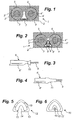
- Figs. 1 and 2 the same part of a rotating electric machine 1 is shown, the machine having a rotor (not shown), a stator 2, and stator windings 3,4.
- the windings 3, 4 include high voltage cable having an insulating coating 3', 4' and a core 3'', 4" of conductors.
- the windings 3, 4 are drawn through slots 5, 6 in the stator 2, the slots being interconnected and a little wider than the windings 3, 4.
- a support member 7, 8 is arranged within the slots 5, 6, to be precise inside the interconnecting part of the slots 5, 6 as can be seen in the drawing.
- the prior art support member 7, shown in Fig. 1, comprises a hose which is shown in a collapsed state in which it is able to be threaded through the slots 5, 6 between the windings 3, 4. After being threaded through the hose shaped support member 7 is sealed at one end and filled with a hardening mass, such as epoxy resin. The mass is makes the support member 7 expand, locking the windings 3, 4 inside the slots 5, 6.
- the support member 8 does not have to be filled with e.g. epoxy resin. It comprises a hose 8' with a substantially triangular cross-section (cf. Fig. 2) well fitting the interconnecting part of the slots 5, 6 through which it extends in contact with the windings 3, 4.
- a wire 9 extends there through, the wire 9 being made of a non-stretchable material, such as steel, and having at least twice the length of a stator slot 5, 6.
- the wire is attached to the front or insertion end support member 8 by means of a ring 10 (cf. Fig. 3) which is clamped onto said insertion end.
- a shrinking tube 11 is thereafter placed on said insertion end (cf. Fig. 4) covering said ring 10 and tightening the joint between the wire 9 and the support member hose 8'.
- a first alternative embodiment of a support member 12 is shown. It comprises a hose 13 with a substantially triangular cross-section, having a lip 14 extending along one of the hose walls.
- the purpose of the lip 14 is to help the hose 13 support the stator windings 5, 6 as does the wire in the previous embodiment.
- the wire consists of several reinforcement threads 15 being embedded in the hose walls.
- a second alternative embodiment of a support member 16 is shown. It comprises a hose 17 with a substantially triangular cross-section, having a lip 18 extending along one of the hose walls.
- the wire consists of one reinforcement thread 19 being embedded in said lip 18.
Landscapes
- Engineering & Computer Science (AREA)
- Power Engineering (AREA)
- Insulation, Fastening Of Motor, Generator Windings (AREA)
- Iron Core Of Rotating Electric Machines (AREA)
Abstract
Description
Claims (10)
- A rotating electric machine having a rotor, a stator (2), and stator windings (3, 4), the windings (3, 4) including high voltage cable drawn through slots (5, 6) in the stator (2), wherein support members (8; 12; 16) are arranged inside the slots (5, 6) along and in contact with the windings (3, 4), said support members (8; 12; 16) comprising a hose (8'; 13, 17) with a substantially triangular cross-section, characterized in that a wire (9; 15; 19) is extending through and being attached to each support member (8; 12; 16).
- A rotating machine according to claim 1, wherein an insertion part of the wire (9), said part having a length corresponding to at least the length of a slot (5, 6), protrudes at an insertion end of each support member (8).
- A rotating machine according to claim 2, wherein said wire (9) is attached to each support member (8) by means of a ring (10) which is clamped onto said insertion end.
- A rotating machine according to claim 3, wherein a shrinking tube (11) is placed on said insertion end covering said ring (10).
- A rotating machine according to claim 1, wherein said wire consists of at least one reinforcement thread (15, 19) being embedded in a hose wall.
- A rotating machine according to claim 5, wherein said hose wall has a lip (14; 18) extending along said hose wall and having a substantially triangular cross-section.
- A rotating machine according to claim 6, wherein said at least one reinforcement thread (19) is embedded in said lip (18).
- Method of mounting a support member (8; 12; 16) in a rotating electric machine (1) having a rotor, a stator (2), and stator windings (3, 4), the windings (3, 4) including high voltage cable drawn through slots (5, 6) in the stator (2), wherein support members (8; 12; 16) are arranged inside the slots (5, 6) along and in contact with the windings (3, 4), said support members (8; 12; 16) comprising a hose (8'; 13; 17) with a substantially triangular cross-section, characterized in that air inside a support member (8; 12; 16) is evacuated in order to shrink the support member (8; 12; 16), that a wire (9; 15; 19) extending through the support member (8; 12; 16) is used to pull the evacuated support member (8; 12; 16) into a slot (5, 6), and that the evacuated support member (8; 12; 16) is expanded by releasing the vacuum inside in order to make it clamp a cable inside a slot (5, 6) of the stator (2) .
- Method according to claim 8, wherein said wire (9) is inserted into a support member (8) and attached to an insertion end of it by means of a ring (10) which is clamped on said end.
- Method according to claim 9, wherein a shrinking tube (11) is placed on said insertion end and shrunk to tightly enclose said ring (10).
Applications Claiming Priority (2)
| Application Number | Priority Date | Filing Date | Title |
|---|---|---|---|
| SE0202489A SE0202489D0 (en) | 2002-08-22 | 2002-08-22 | Suport members inside stator slots of a rotating electric machine and method of mounting these support members |
| SE0202489 | 2002-08-22 |
Publications (3)
| Publication Number | Publication Date |
|---|---|
| EP1391977A2 true EP1391977A2 (en) | 2004-02-25 |
| EP1391977A3 EP1391977A3 (en) | 2006-08-09 |
| EP1391977B1 EP1391977B1 (en) | 2010-05-05 |
Family
ID=20288772
Family Applications (1)
| Application Number | Title | Priority Date | Filing Date |
|---|---|---|---|
| EP03405573A Expired - Lifetime EP1391977B1 (en) | 2002-08-22 | 2003-07-31 | Support members inside stator slots of a rotating electric machine and method of mounting these support members |
Country Status (5)
| Country | Link |
|---|---|
| US (1) | US6981308B2 (en) |
| EP (1) | EP1391977B1 (en) |
| CA (1) | CA2437719C (en) |
| DE (1) | DE60332418D1 (en) |
| SE (1) | SE0202489D0 (en) |
Cited By (1)
| Publication number | Priority date | Publication date | Assignee | Title |
|---|---|---|---|---|
| CN102386736A (en) * | 2011-12-13 | 2012-03-21 | 许晓华 | Permanent magnet synchronous motor and modification method thereof |
Family Cites Families (6)
| Publication number | Priority date | Publication date | Assignee | Title |
|---|---|---|---|---|
| SU961048A1 (en) * | 1979-12-06 | 1982-09-23 | Научно-Исследовательский Сектор Всесоюзного Ордена Ленина Проектно-Изыскательского И Научно-Исследовательского Института "Гидропроект" Им.С.Я.Жука | Generator stator |
| GB2076597A (en) * | 1980-05-16 | 1981-12-02 | Aei | Securing Windings in an Electrical Rotating Machine |
| US6972505B1 (en) * | 1996-05-29 | 2005-12-06 | Abb | Rotating electrical machine having high-voltage stator winding and elongated support devices supporting the winding and method for manufacturing the same |
| US5807447A (en) * | 1996-10-16 | 1998-09-15 | Hendrix Wire & Cable, Inc. | Neutral conductor grounding system |
| US6278217B1 (en) * | 1999-12-09 | 2001-08-21 | General Electric Company | High voltage generator stator with radially inserted cable windings and assembly method |
| DE20009286U1 (en) * | 2000-05-23 | 2000-09-07 | Partzsch, Thomas, Dipl.-Ing., 04720 Döbeln | Winding wire for electrical machines |
-
2002
- 2002-08-22 SE SE0202489A patent/SE0202489D0/en unknown
-
2003
- 2003-07-31 DE DE60332418T patent/DE60332418D1/en not_active Expired - Lifetime
- 2003-07-31 EP EP03405573A patent/EP1391977B1/en not_active Expired - Lifetime
- 2003-08-11 US US10/637,569 patent/US6981308B2/en not_active Expired - Fee Related
- 2003-08-20 CA CA2437719A patent/CA2437719C/en not_active Expired - Fee Related
Cited By (2)
| Publication number | Priority date | Publication date | Assignee | Title |
|---|---|---|---|---|
| CN102386736A (en) * | 2011-12-13 | 2012-03-21 | 许晓华 | Permanent magnet synchronous motor and modification method thereof |
| CN102386736B (en) * | 2011-12-13 | 2013-10-16 | 浙江联宜电机股份有限公司 | Permanent magnet synchronous motor and modification method thereof |
Also Published As
| Publication number | Publication date |
|---|---|
| EP1391977A3 (en) | 2006-08-09 |
| SE0202489D0 (en) | 2002-08-22 |
| DE60332418D1 (en) | 2010-06-17 |
| US20040056551A1 (en) | 2004-03-25 |
| CA2437719A1 (en) | 2004-02-22 |
| EP1391977B1 (en) | 2010-05-05 |
| US6981308B2 (en) | 2006-01-03 |
| CA2437719C (en) | 2011-05-17 |
Similar Documents
| Publication | Publication Date | Title |
|---|---|---|
| US7456539B2 (en) | Rotor and method of manufacturing the same | |
| US8558427B2 (en) | Insulation assembly for electric machine | |
| FI92247B (en) | Connector for corrugated pipe | |
| CA1324643C (en) | Cable entry device | |
| CN104253342B (en) | Electric connector with cold events part | |
| US4215464A (en) | Method of making a stator connection assembly | |
| JP2010532550A (en) | Adapter, cable with adapter and cable connector assembly | |
| EP1860749B1 (en) | Support coil comprising a mechanical locking means and method for the production thereof | |
| JP2023536508A (en) | Coupling device and method for pulling electrical wire through conduit | |
| US10424984B2 (en) | Rotating electrical machine coil, production method of rotating electrical machine coil, and rotating electrical machine | |
| US3748511A (en) | Stator lead anchoring and splice-insulating slot insulator structure and method | |
| US6981308B2 (en) | Support members inside stator slots of a rotating electric machine and method of mounting these support members | |
| US3862492A (en) | Method for production of stator lead anchoring and splice-insulating slot insulator structure | |
| KR102121714B1 (en) | Press sleeve for connecting cable and cable connecting method | |
| US8339002B2 (en) | End winding for an electrical machine, and method for its production | |
| KR101188059B1 (en) | Cable jointing method using spiral core | |
| KR102602572B1 (en) | Branch sleeve for power distribution line and its construction method | |
| KR20210029133A (en) | Method injecting lubricant of buried type pipe conditioner | |
| CN100502166C (en) | Commutator and method for manufacturing same | |
| JP6985650B2 (en) | Composite tube and terminal connection | |
| RU2382428C2 (en) | Method for superposition of electric insulating shell over varistor unit, and also varistor unit for overvoltage protection discharger | |
| JP2968187B2 (en) | Lead wire fixing device for rotating machine stator | |
| US2443456A (en) | Dynamoelectric machine | |
| JP6089010B2 (en) | Power cable connecting apparatus and power cable connecting method | |
| JP2015104190A (en) | Holding structure for cables, and holding method for cable |
Legal Events
| Date | Code | Title | Description |
|---|---|---|---|
| PUAI | Public reference made under article 153(3) epc to a published international application that has entered the european phase |
Free format text: ORIGINAL CODE: 0009012 |
|
| AK | Designated contracting states |
Kind code of ref document: A2 Designated state(s): AT BE BG CH CY CZ DE DK EE ES FI FR GB GR HU IE IT LI LU MC NL PT RO SE SI SK TR |
|
| AX | Request for extension of the european patent |
Extension state: AL LT LV MK |
|
| RAP1 | Party data changed (applicant data changed or rights of an application transferred) |
Owner name: ALSTOM TECHNOLOGY LTD |
|
| PUAL | Search report despatched |
Free format text: ORIGINAL CODE: 0009013 |
|
| AK | Designated contracting states |
Kind code of ref document: A3 Designated state(s): AT BE BG CH CY CZ DE DK EE ES FI FR GB GR HU IE IT LI LU MC NL PT RO SE SI SK TR |
|
| AX | Request for extension of the european patent |
Extension state: AL LT LV MK |
|
| 17P | Request for examination filed |
Effective date: 20061229 |
|
| AKX | Designation fees paid |
Designated state(s): DE GB SE |
|
| GRAP | Despatch of communication of intention to grant a patent |
Free format text: ORIGINAL CODE: EPIDOSNIGR1 |
|
| GRAS | Grant fee paid |
Free format text: ORIGINAL CODE: EPIDOSNIGR3 |
|
| GRAA | (expected) grant |
Free format text: ORIGINAL CODE: 0009210 |
|
| AK | Designated contracting states |
Kind code of ref document: B1 Designated state(s): DE GB SE |
|
| REG | Reference to a national code |
Ref country code: GB Ref legal event code: FG4D |
|
| REF | Corresponds to: |
Ref document number: 60332418 Country of ref document: DE Date of ref document: 20100617 Kind code of ref document: P |
|
| PG25 | Lapsed in a contracting state [announced via postgrant information from national office to epo] |
Ref country code: SE Free format text: LAPSE BECAUSE OF FAILURE TO SUBMIT A TRANSLATION OF THE DESCRIPTION OR TO PAY THE FEE WITHIN THE PRESCRIBED TIME-LIMIT Effective date: 20100505 |
|
| PLBE | No opposition filed within time limit |
Free format text: ORIGINAL CODE: 0009261 |
|
| STAA | Information on the status of an ep patent application or granted ep patent |
Free format text: STATUS: NO OPPOSITION FILED WITHIN TIME LIMIT |
|
| 26N | No opposition filed |
Effective date: 20110208 |
|
| REG | Reference to a national code |
Ref country code: DE Ref legal event code: R097 Ref document number: 60332418 Country of ref document: DE Effective date: 20110207 |
|
| PGFP | Annual fee paid to national office [announced via postgrant information from national office to epo] |
Ref country code: GB Payment date: 20110622 Year of fee payment: 9 |
|
| PGFP | Annual fee paid to national office [announced via postgrant information from national office to epo] |
Ref country code: DE Payment date: 20110729 Year of fee payment: 9 |
|
| GBPC | Gb: european patent ceased through non-payment of renewal fee |
Effective date: 20120731 |
|
| PG25 | Lapsed in a contracting state [announced via postgrant information from national office to epo] |
Ref country code: GB Free format text: LAPSE BECAUSE OF NON-PAYMENT OF DUE FEES Effective date: 20120731 Ref country code: DE Free format text: LAPSE BECAUSE OF NON-PAYMENT OF DUE FEES Effective date: 20130201 |
|
| REG | Reference to a national code |
Ref country code: DE Ref legal event code: R119 Ref document number: 60332418 Country of ref document: DE Effective date: 20130201 |