EP1391843A2 - Procédé de détection des pixels de teinte Y dans une image I et dispositif pour la mise en oeuvre du procédé - Google Patents
Procédé de détection des pixels de teinte Y dans une image I et dispositif pour la mise en oeuvre du procédé Download PDFInfo
- Publication number
- EP1391843A2 EP1391843A2 EP03017992A EP03017992A EP1391843A2 EP 1391843 A2 EP1391843 A2 EP 1391843A2 EP 03017992 A EP03017992 A EP 03017992A EP 03017992 A EP03017992 A EP 03017992A EP 1391843 A2 EP1391843 A2 EP 1391843A2
- Authority
- EP
- European Patent Office
- Prior art keywords
- image
- pixels
- pixel
- colorimetric
- hue
- Prior art date
- Legal status (The legal status is an assumption and is not a legal conclusion. Google has not performed a legal analysis and makes no representation as to the accuracy of the status listed.)
- Withdrawn
Links
Images


Classifications
-
- G—PHYSICS
- G06—COMPUTING OR CALCULATING; COUNTING
- G06V—IMAGE OR VIDEO RECOGNITION OR UNDERSTANDING
- G06V40/00—Recognition of biometric, human-related or animal-related patterns in image or video data
- G06V40/10—Human or animal bodies, e.g. vehicle occupants or pedestrians; Body parts, e.g. hands
- G06V40/16—Human faces, e.g. facial parts, sketches or expressions
- G06V40/161—Detection; Localisation; Normalisation
- G06V40/162—Detection; Localisation; Normalisation using pixel segmentation or colour matching
-
- G—PHYSICS
- G06—COMPUTING OR CALCULATING; COUNTING
- G06V—IMAGE OR VIDEO RECOGNITION OR UNDERSTANDING
- G06V10/00—Arrangements for image or video recognition or understanding
- G06V10/20—Image preprocessing
- G06V10/26—Segmentation of patterns in the image field; Cutting or merging of image elements to establish the pattern region, e.g. clustering-based techniques; Detection of occlusion
- G06V10/267—Segmentation of patterns in the image field; Cutting or merging of image elements to establish the pattern region, e.g. clustering-based techniques; Detection of occlusion by performing operations on regions, e.g. growing, shrinking or watersheds
-
- G—PHYSICS
- G06—COMPUTING OR CALCULATING; COUNTING
- G06V—IMAGE OR VIDEO RECOGNITION OR UNDERSTANDING
- G06V10/00—Arrangements for image or video recognition or understanding
- G06V10/20—Image preprocessing
- G06V10/28—Quantising the image, e.g. histogram thresholding for discrimination between background and foreground patterns
-
- G—PHYSICS
- G06—COMPUTING OR CALCULATING; COUNTING
- G06V—IMAGE OR VIDEO RECOGNITION OR UNDERSTANDING
- G06V10/00—Arrangements for image or video recognition or understanding
- G06V10/40—Extraction of image or video features
- G06V10/56—Extraction of image or video features relating to colour
Definitions
- the invention relates to a method for detecting pixels of a given hue Y in an image I and a device suitable for the implementation of this method.
- Such a method is used in particular to detect the "flesh” hue of a skin. human in a picture. Many applications require localization of the "flesh” shade. Examples include the detection and monitoring of faces human, hand tracking, advanced human-machine interfaces, indexing video, image database filtering, etc.
- the value of the binary mask applied to the pixel p is equal to 1 when each of the k components of this pixel p in the color space C, is included in a "flesh" shade interval.
- Detection methods of the second type are in fact based on two detection modes.
- the second detection mode consists in modeling the colorimetric distribution of the "flesh” shade by a Gaussian or a mixture of Gaussians. This modeling is carried out by learning from histograms obtained by manual labeling of the pixels of "flesh” hue. Each Gaussian distribution is then characterized by its mean and its covariance matrix. The color c of a pixel p can be compared to the distribution model of the "flesh” hue by calculating the Mahalanobis distance. If this distance is less than a fixed threshold, the pixel p is considered to be part of a region of hue "flesh".
- the first detection step consists of extract skin tone pixels from the image by color thresholding in space HSV colorimetric, using a main polyhedron (PP).
- An analysis of the saturation histogram of the skin tone pixels detected during this first detection step forms a threshold secondary polyhedron (SP) colorimetric, taking into account the level of saturation of the image.
- SP threshold secondary polyhedron
- Modeling then consists in segmenting the skin tone pixels detected during this first detection step in order to obtain “HRi” regions and to generate Oi objects correspondents.
- the second detection step pixels are extracted from the image skin tone using the secondary polyhedron (SP), in the HSV color space, we calculate the color distance between each extracted pixel and the center of each object Oi and, if the calculated distance is less than a certain threshold, we add the pixel considered to object Oi.
- the second detection step therefore makes it possible to growing the flesh-colored regions detected during the first detection step, in the HSV color space.
- the process proposed by HERODOTOU has very limited performances adaptation to lighting conditions because only the polyhedron formation stage secondary takes into account the lighting conditions.
- the problem of the invention consists therefore to propose a method for detecting pixels of a given hue Y in a image I composed of a plurality of pixels p, more robust under lighting conditions, without, however, requiring too much computing time.
- the second detection step is carried out in space image and makes it possible to grow the spatial regions of hue Y detected during the first step of detection in image space.
- the second detection step allows therefore to assign pixels J which are spatially neighboring in image space to image J and which, due to this proximity, are subject to the same lighting conditions. So, if the image J is rather achromatic, it may extend to areas also achromatic. On the other hand, if the image J is rather of classic Y hue (not achromatic), it can only extend to areas with very bright colors close to classic Y colors. Detection is therefore extremely robust vis-à-vis lighting conditions. In addition, only the pixels spatially neighboring image J are compared to the color model, which considerably limits the calculations.
- the number of pixels of hue Y of the image J is increased by inserting therein pixels detected step by step during the second detection step. For each new pixel of hue Y inserted in image J, we examine each pixel neighbor of this new pixel of shade Y, contained in image J but not already taken into account account in image J, we determine if this pixel is of hue Y and, if this is the case, we insert it into image J.
- the second step of detecting pixels of shade Y consists in calculating the colorimetric distance between each of the pixels of the subset V and the color model created from image J and to determine if this distance colorimetric is below a predefined threshold.
- the first step of detecting pixels of hue Y of image I we can detect pixels of hue Y in image I by a thresholding operation colorimetric consisting in comparing, for each pixel of image I, at least one color component of this pixel at a predefined color interval of hue Y.
- the method of detecting pixels of hue Y by colorimetric thresholding has the advantage of reliably detecting pixels of hue Y.
- the first detection operation by color thresholding certainly lets escape pixels of Y hue, but these are anyway subsequently detected by the second detection operation.
- a step of segmenting the image J consisting of forming m colorimetric agglomerates A i from the pixels of hue Y of the image J and the modeling step consists of modeling each of the m agglomerates A i in order to create m colorimetric models M (A i ) of hue Y, each colorimetric model M (A i ) of hue Y being associated with the agglomerate A i from which said model was created.
- the operation consisting in forming m colorimetric agglomerates A i from the hue pixels Y of the image J, detected during the first detection step, makes it possible to create colorimetric models of hue Y.
- the creation of several colorimetric models of Hue Y makes the detection of Y hue pixels more precise and therefore more reliable.
- the image J is decomposed into x spatial zones Z i, j of shade Y, with 1 ⁇ i ⁇ m, j ⁇ 1 and x ⁇ m , each containing a block of pixels close to each other and belonging to the same color agglomerate A i .
- a map is thus formed from image J comprising x spatial zones Z i, j of shade Y linked to the various colorimetric agglomerates A i .
- the second detection step consists, for each of the zones Z i, j of color Y linked to a given colorimetric agglomerate A i , to select pixels of the image I spatially neighboring this zone Z i, j of color Y, the set of pixels thus selected forming a subset V Zi, j, to calculate the colorimetric distance between each of the pixels of the subset V Zi, j and the colorimetric model M (A i ) of the associated shade Y to the agglomerate A i and to determine whether this distance is less than the predefined threshold in order, if this is the case, to assign said pixel to said zone Z i, j of shade Y.
- the first step 1 of detecting flesh-colored pixels is carried out in a color space C 1 , here the HSV space. It is a three-dimensional space (H, S and V) in which the dimensions H, S and V respectively represent the hue, which defines the color perceived by the human eye, the saturation, which defines the quantity of white in the color, and luminance, which defines the brightness of the color.
- a colorimetric thresholding operation is carried out which consists in comparing, for each pixel of image I, at least one colorimetric component of this pixel with a predefined color tint interval, in space C 1 (HSV).
- HSV space C 1
- a "skin tone color interval" is an interval occupied by the majority of skin tone pixels.
- the comparison relates only to the H and S components of the pixels of image I.
- the dimension V is not taken into account in order to make detection by colorimetric thresholding more robust vis- with regard to lighting conditions.
- the colorimetric skin tone interval is determined for each of the dimensions H and S by experimentation.
- the flesh tone interval [H min , H max ] for the dimension H occupies the range of values [330, 30] and the flesh tone interval [S min , S max ] for dimension S occupies the range of values [0.20, 0.54].
- the computation of the binary mask MB therefore consists in assigning the value "1" to the pixels p whose components I H (p) and I S (p) are respectively included in the intervals [H min , H max ] and [S min , S max ], and the value "0" to the other pixels, the pixels carrying the value "1" being considered to be skin tone.
- the calculation of the binary mask thus makes it possible to detect at least a portion of the flesh-colored pixels.
- an image J of flesh tint is formed such that:
- Image J includes only the skin tone pixels of the original image I detected during the first detection step 1, the value "0" being assigned to the others pixels of the original image I.
- the segmentation step 3 consists in forming m colorimetric agglomerates A i , here in space C 1 (ie HSV), from the flesh-colored pixels of the image J.
- the histogram H (J) represents a colorimetric distribution of the pixels having been detected as being of flesh tint during the first detection step 1.
- the modes of the histogram H (J) constituted are determined by the hues with the highest pixel densities, in other words the hues most common human flesh in image J, by an estimation method of density per nucleus.
- an estimation method of density per nucleus we use a method density estimation by nucleus of type "Mean Shift", which will now be explained.
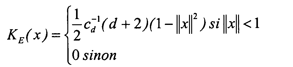
- the kernel K (x) is a satisfying scalar function:
- the Mean Shift procedure consists of finding areas of high density in space . To do this, we calculate the density gradient which can be approximated by the gradient of the density estimate:
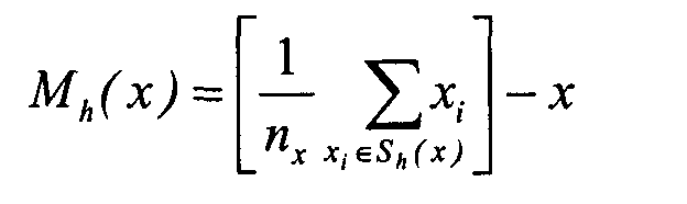
- S h (x) denotes the hypersphere of dimension d, of radius h, of volume h d c d , containing n x point and centered in x .
- S h (x) is called the uniform nucleus.
- the quantity M h (x) is called the Mean Shift sample and the quantity f and U (x) defines the density estimate with the uniform nucleus of radius h.
- the estimate of the density gradient at point x can be calculated from the Mean Shift sample using a uniform kernel centered at x .
- the Mean Shift vector M h (x) has the direction of the gradient of the density estimate in x when this estimate uses the Epanechnikov kernel.
- the point x defines a path converging towards a maximum density.
- the method of estimation of Mean Shift is applied to l image J, in a C 2 color space, in this case the Luv space.
- the radius r of the nucleus in other words the size of the search window, determined in sub-step 3b-i), is here proportional to the trace of the covariance matrix of image J. The calculation of this matrix is performed as follows:
- (p 1 , p 2 , ..., p n ) be the set of n pixels p x of the image J such that J ( p x ) ⁇ 0, i.e. the pixels detected as being of skin tone during the first step 1 of detecting skin tone pixels by colorimetric thresholding in the HSV space.
- Each of the pixels p x is characterized by a vector determining the color of p i in the space Luv:
- Each "vector pixel" p x is then centered on the average color vector resulting in a "centered vector pixel" p x:
- the diagonal of the covariance matrix gives the variance in the dimensions L, u and v.
- step 3b-iv After possible deletion of one or more convergence points in step 3b-iv), we obtain m convergence points pc i (1 ⁇ i ⁇ m and m ⁇ k). Each of these m points of convergence pc i defines the center of a high color density of flesh-colored pixels, in other words a mode of the histogram H (J). The m modes of the histogram H (j) therefore respectively represent the m most common skin tones in the image J.
- a “colorimetric agglomerate A i " is characterized by a mode of the histogram pc i , and contains a set of pixels close in the colorimetric sense, that is to say of close hue, of this mode pc i .
- the nearest neighbor algorithm therefore consists of assigning, or associating, the flesh-colored pixel p x of image J to the agglomerate A i if the colorimetric distance between this pixel p x and the mode pc i associated with the agglomerate A i is less than each of the color distances between this pixel p and the other modes pc j ⁇ i of the image J.
- the image J is decomposed into x spatial zones, or regions Z i, j (with 1 ⁇ i ⁇ m, j ⁇ 1) of flesh tint.
- Each zone Z i, j contains a block of neighboring flesh-colored pixels, in pairs contact by at least one side of the pixel, and belonging to the same colorimetric agglomerate A i .
- a flesh-colored zone Z i, j is linked to, or associated with, an agglomerate A i when it contains pixels belonging to this agglomeration A i .
- the number x of spatial zones Z i, j is greater than or equal to the total number m of colorimetric agglomerates, depending on whether the pixels of each agglomerate A i all belong to the same spatial zone Z i, j or to different zones spatial Z i, j .
- each agglomerate A i is modeled by the colorimetric mean of the pixels which compose it. Any other modeling method could be considered.
- the modeling step 4 is followed by a second step 5 of detecting flesh-colored pixels aimed at increasing the skin-tone areas Z i, j of the image J.
- image space designates the graphic space, here two-dimensional, containing the images, or graphic representations, I and J.
- Detection step 5 uses a modified version of a segmentation algorithm by watershed.
- This algorithm uses a "minimal heap” type data structure.
- this tree is a balanced binary tree containing N nodes, each node being connected to an upper node and to two lower nodes with the exception of the end nodes comprising a higher root node and nodes lower leaves.
- the heap has the property of "minimal heap" if the distance d x associated with each node e x is less than the distance d x 'associated with each node e x ' located below the node e x .
- the minimum distance d min absolute from the tree is that which is located at the root e root of the tree.
- the tree is such that the distance d min from the root node of the tree e root is less than the size r of the search window used in step 3b-iii) by the method of estimating the density.
- the operations of inserting or deleting nodes in the tree must be followed by a reorganization of the heap by swapping of nodes in order to preserve the ownership of the heap.
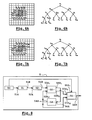
- FIG. 6A shows, by way of illustrative example, a representation of a spatial zone Z i, j of flesh tint of the image J, linked to a colorimetric agglomerate A i and N pixels P x (1 ⁇ x ⁇ N ) of the image I neighbors of this flesh-colored zone Z i, j, N being here equal to 18.
- the node e 5 in FIG. 6B constitutes the root node of the tree.
- steps 5a) to 5g) is carried out here for all the zones Z i, j in order to form a single global heap, for all the zones Z i, j .
- steps 5a) to 5g) are carried out here for all the zones Z i, j in order to form a single global heap, for all the zones Z i, j .
- FIG. 7A the flesh-colored zone Z i, j of FIG. 6A is shown enlarged by insertion of the root pixel p 5 and the new neighboring pixels of the region A i , namely q 19 and q 20 .
- FIG. 7B represents the heap of FIG. 6B reorganized after extraction of the root pixel p 5 and insertion of the new neighboring pixel q 19 .
- the pixel q 20 is not inserted into the heap because the color distance between this pixel and the model M (A i ) is greater than the size r of the search window.
- step 5c the pixel p x is inserted into the zone Z i, j with which it is spatially neighboring.
- step 5d we proceed to step 5d) aiming to determine if there is one or more pixel (s) q x neighbor (s) of the new pixel p x , but not belonging to the zone Z i, j and of color close to that of the model M (A i ) of the colorimetric agglomerate A; associated with this zone Z i, j .
- step 5d) is partially analogous to step Sa): First, it is detected whether there are one or more new pixel (s) q x of the image I, not contained in the zone Z i, j and spatially neighbors (that is to say in image space) of the new pixel p x inserted in the zone Z i, j .
- step 5d we end step 5d and go to step 5b for extracting the root of the heap. Otherwise, the steps which have just been described are repeated (that is to say steps 5a-iii) to 5a-viii) applied to the new neighboring pixels q x ), until the neighborhood subset V Zi, j be empty.
- a device 5 shown in FIG. 8, comprising a module 50 for storing an image I, a first module 51 for detecting skin tone pixels, a training module 52 of an image J, a module 53 for segmenting the image J, a modeling module 54 and a second module 55 for detecting flesh-colored pixels.
- the storage module 50 is intended to record and store an image I and is connected to an input 51A of the first detection module 51.
- the latter is arranged to detect at least part of the flesh-colored pixels of the image I , as previously explained in step 1 of the method, and in delivering, at output 51B, the skin tone pixels thus detected.
- the first detection module 51 detects flesh-colored pixels of the image I here by colorimetric thresholding, in the HSV space, using the flesh-colored intervals [H min , H max ] and [S min , S max ] obtained by experimentation.
- the module 52 for forming the image J is arranged to form an image J containing the flesh-colored pixels detected by the first detection module 51 (step 2 of the method). It includes an input 52A, connected to the output 51B of the detection module 51, and an output 52B intended to deliver the image J such that:
- the segmentation module 53 is arranged to form m colorimetric agglomerates A i from the flesh-colored pixels of the image J and to decompose the image J into x spatial zones Z i, j with 1 ⁇ i ⁇ m, j ⁇ 1 and x ⁇ m each containing a block of neighboring pixels belonging to the same colorimetric agglomerate A i , as previously explained in step 3 of the method.
- the segmentation module 53 includes two inputs 53A 1 and 53A 2 and two outputs 53B 1 and 53B 2 .
- the input 53A 1 and the output 53B 1 are respectively connected to the output 52B of the segmentation module and to an input 54A of the modeling module 54, while the input 53A 2 and the output 53B 2 are respectively connected to the output 54B of the modeling module and to an input 55A of the second detection module 55.
- the outputs 53B 1 and 53B 2 are intended to deliver the m colorimetric agglomerates A i and the x zones Z i, j .
- the modeling module 54 is arranged to create m colorimetric model of skin tone from the m colorimetric agglomerates A i , as previously explained in step 4 of the method. It includes an input 54A connected to the output 53B 1 of the segmentation module and an output 54B intended to deliver m colorimetric models of flesh tint M (A i ) respectively created from m colorimetric agglomerates A i .
- the second detection module 55 is arranged to detect flesh-colored pixels in the image J, as previously explained in step 5 of the method. It includes three inputs 55A 1 , 55A 2 and 55A 3 respectively connected to the storage module 50, to the output 53B 2 of the segmentation module 53 and to the output 54B of the modeling module 54. In operation, the detection module 55 receives , by the inputs 55A 1 , 55A 2 and 55A 3 , the image I, the image J comprising x zones Z i, j of flesh tint and the colorimetric models of flesh tint M (A i ), respectively, and delivers by the output 54B the set of skin tone pixels detected.
- the subset V Zi, j of pixels neighboring the area, or spatial region Z i, j contains the pixels adjacent to the flesh-colored pixels of the area Z i, j of the image J, that is to say in contact with pixels of the zone Z i, j either by one side or by a vertex.
- step 1 of detecting flesh-colored pixels by colorimetric thresholding is performed in the HSV color space while the steps consisting in forming the m colorimetric agglomerates and in modeling them in order to create m colorimetric models M (A i ) of flesh color are made in the Luv color space.
- the detection method of the invention could be applied to the detection of pixels of hue Y different from a skin tint.
Landscapes
- Engineering & Computer Science (AREA)
- Physics & Mathematics (AREA)
- General Physics & Mathematics (AREA)
- Multimedia (AREA)
- Theoretical Computer Science (AREA)
- Health & Medical Sciences (AREA)
- General Health & Medical Sciences (AREA)
- Oral & Maxillofacial Surgery (AREA)
- Human Computer Interaction (AREA)
- Image Analysis (AREA)
- Image Processing (AREA)
- Spectrometry And Color Measurement (AREA)
Abstract
Description

- TC(p) désigne la valeur du masque binaire à la position p ;
- Ii(p) désigne la composante colorimétrique du pixel p dans l'image I suivant la dimension i de l'espace colorimétrique considéré C.
- p(c|chair) et p(c|¬chair) désignent respectivement la probabilité d'avoir la couleur c comme couleur "chair" et couleur non "chair". Ces probabilités sont facilement calculables à partir des deux histogrammes construits ;
- p(chair) et p(¬chair) désignent respectivement la probabilité d'obtenir de la teinte "chair" et non "chair" quelle que soit la couleur. Ces probabilités peuvent être approchées en étudiant les distributions dans les deux histogrammes construits.
- on insère les pixels du sous-ensemble V séparés du modèle colorimétrique de teinte Y par une distance colorimétrique inférieure audit seuil dans une structure de données de type tas minimal de manière à former un arbre comprenant des noeuds ex, constitués chacun d'un couple (px, dx) dans lequel px et dx représentent respectivement un pixel de l'image I, voisin d'un pixel de teinte Y de l'image J et non pris en compte dans l'image J, et la distance colorimétrique entre ce pixel px et ledit modèle colorimétrique, l'arbre étant tel que la distance dx associée à chaque noeud ex est inférieure à la distance dx' associée à chaque noeud ex' situé en-dessous du noeud ex et la distance colorimétrique dmin associée au noeud racine eracine est inférieure au rayon r du noyau utilisé par la méthode d'estimation de densité, et
- on affecte le pixel pracine du noeud racine eracine de l'arbre à l'image J.
- - il comprends de moyens pour former une image J contenant les pixels de teinte Y détectés par les premiers moyens de détection,
- - les seconds moyens de détection sont agencés pour former ledit sous-ensemble V à l'aide des pixels voisins des pixels de teinte Y de l'image J dans l'espace image et pour insérer dans l'image J les nouveaux pixels p de teinte Y détectés.
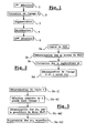
- les figures 1 à 5 représentent des organigrammes du mode de réalisation particulier du procédé de l'invention;
- la figure 6A représente une zone Zi,jde teinte Y de l'image I, liée à un agglomérat colorimétrique Ai, et un sous-ensemble voisinage VZi,j associé à cette zone Zi,j de teinte Y;
- la figure 6B représente une structure de données de type tas minimale formée à partir du sous-ensemble voisinage VZi,jde la figure 6A;
- la figure 7A représente la zone Zi,j de teinte Y et le sous-ensemble voisinage VZi,jde la figure 6A, après insertion de la racine du tas de la figure 6B;
- la figure 7B représente le tas de la figure 6B après insertion de la racine du tas et insertion d'un nouveau pixel voisin de la zone Zi,jde teinte Y;
- la figure 8 représente un schéma bloc fonctionnel de la forme de réalisation particulière du dispositif de l'invention.
- une première étape 1 de détection de pixels de teinte chair, consistant à détecter au moins une partie des pixels de teinte chair dans l'image d'origine I,
- une étape 2 de formation d'une image J contenant les pixels de teinte chair détectés lors de la première étape de détection 1 ;
- une étape 3 de segmentation de l'image J consistant à former m agglomérats colorimétriques Ai de teinte chair à partir des pixels de teinte chair de l'image J, dans un espace colorimétrique, et à décomposer l'image J en x zones, ou régions, spatiales Zi,jde teinte Y (avec 1 ≤ i ≤ m, j ≥ 1 et donc x ≥ m ) contenant chacune un bloc de pixels de teinte Y voisins les uns des autres (c'est-à-dire ici en contact deux à deux par au moins un côté de pixel) et appartenant à un agglomérat colorimétrique donné Ai,
- une étape de modélisation 4 consistant à modéliser chacun des m agglomérats Ai afin de créer m modèles colorimétriques M(A;) de teinte chair, chaque modèle colorimétrique M(Ai) de teinte chair étant associé à l'agglomérat Ai à partir duquel il a été créé,
- une seconde étape 5 de détection de pixels de teinte chair consistant, pour chaque zone Zi,j de teinte Y de l'image J liée à un agglomérat colorimétrique Ai (c'est-à-dire contenant des pixels appartenant à l'agglomérat colorimétrique Ai), à détecter les pixels de l'image d'origine I voisins spatialement de cette zone Zi,j de teinte Y afin de former un sous-ensemble « voisinage » VZi,j de la zone Zi,j considérée, à comparer chacun des pixels de VZi,j au modèle colorimétrique M(Ai) associé à l'agglomérat Ai afin de déterminer si sa couleur est suffisamment proche de celle du modèle M(Ai) pour qu'il puisse être considéré comme un pixel de teinte chair et, si tel est le cas, d'affecter le pixel considéré à la zone Zi,j de teinte Y liée à l'agglomérat Ai.
- l'angle H dans le plan de la base du cône, avec 0≤H≤360°,
- la distance à l'axe achromatique S, avec 0≤S≤1 et
- la hauteur du cône, avec 0≤V≤255.

- i représente l'une des deux dimensions H et S de l'espace HSV,
- p représente un pixel de l'image I,
- Ii(p) désigne la composante colorimétrique du pixel p suivant la dimension i et
- Ci min,Ci maxreprésentent les deux bornes, inférieure et supérieure, de l'intervalle de teinte chair pour la dimension i.










- A(px ) représente l'agglomérat Ai auquel le pixel px est affecté, ou associé;
- dC2 (J(px), pci) représente la distance colorimétrique entre la couleur J(px) du pixel px et la couleur du mode pci dans l'espace C2 (Luv).

Claims (21)
- Procédé de détection de pixels d'une teinte donnée Y dans une image I composée d'une pluralité de pixels p, comprenantprocédé caractérisé par le fait queune première étape (1) de détection de pixels de teinte Y consistant à détecter au moins une partie des pixels de teinte Y dans l'image d'origine I,une étape de modélisation (4) consistant à créer au moins un modèle colorimétrique de la teinte Y à partir des pixels de teinte Y détectés lors de la première étape de détection etune seconde étape (5) de détection de pixels de teinte Y consistant, pour chacun des pixels d'un sous-ensemble V de pixels de l'image I none détectés lors de la première étape de détection, à comparer ledit pixel au' modèle colorimétrique préalablement créé afin de déterminer s'il s'agit de pixels'de teinte Y,- il comprend une étape (2) de formation d'une image J contenant les pixels de teinte Y détectés lors de la première étape de détection (1),- dans la seconde étape de détection (5), on forme ledit sous-ensemble V (4a-ii)) à l'aide des pixels voisins des pixels de teinte Y de l'image J (4a-i)) dans l'espace image et- on insère dans l'image J les nouveaux pixels p de teinte Y détectés lors de la seconde étape de détection (4c).
- Procédé selon la revendication 1, dans lequel, à chaque insertion d'un nouveau pixel p dans l'image J,on détermine s'il existe au moins un pixel q de l'image I, non pris en compte dans l'image J et voisin de ce nouveau pixel p de l'image J (4d), etsi tel est le cas, on ajoute ledit pixel voisin q au sous-ensemble V et on réitère la seconde étape de détection en l'appliquant audit pixel q (4d).
- Procédé selon l'une des revendications 1 et 2, dans lequel la seconde étape de détection des pixels de teinte Y consiste à calculer la distance colorimétrique entre chacun des pixels du sous-ensemble V et le modèle colorimétrique créé à partir de l'image J (4a-iii)) et à déterminer si cette distance colorimétrique est inférieure à un seuil prédéfini (4a-iv)).
- Procédé selon la revendication 3, dans lequel pour insérer de nouveaux pixels de teinte Y dans l'image J :on insère (4a-vi)) les pixels du sous-ensemble V séparés du modèle colorimétrique de teinte Y par une distance colorimétrique inférieure audit seuil dans une structure de données de type tas minimal de manière à former un arbre comprenant des noeuds ex, constitués chacun d'un couple (px, dx) dans lequél px et dx représentent respectivement un pixel de l'image I, voisin d'un pixel de teinte Y de l'image J et non pris en compte dans l'image J, et la distance colorimétrique entre ce pixel px et ledit modèle colorimétrique, l'arbre étant tel que la distance dx associée à chaque noeud ex est inférieure à la distance dx' associée à chaque noeud ex' situé en-dessous du noeud ex et la distance colorimétrique dmin associée au noeud racine eracine est inférieure au rayon r du noyau utilisé par la méthode d'estimation de densité, eton affecte le pixel pracine du noeud racine eracine de l'arbre à l'image J (4c).
- Procédé selon la revendication 4, dans lequelpour chaque nouveau pixel px de teinte Y affecté à l'image J, on détermine s'il existe au moins un pixel qx de l'image I non pris en compte dans l'image J et voisin de ce nouveau pixel px (4d),on calcule la distance colorimétrique entre ledit pixel qx et le modèle colorimétrique de la teinte Y (4d) etsi cette distance est inférieure au rayon r du noyau utilisé par la méthode d'estimation de densité, on insère ledit pixel qx dans la structure de données de type tas minimal (4e).
- Procédé selon l'une des revendications 1 à 5, dans lequel, lors de la première étape (1) de détection de pixels de teinte Y de l'image I, on détecte les pixels de teinte Y dans l'image I par une opération de seuillage colorimétrique consistant à comparer, pour chaque pixel de l'image I, au moins une composante colorimétrique de ce pixel à un intervalle colorimétrique prédéfini de teinte Y.
- Procédé selon l'une des revendications 1 à 6, dans lequel il est prévu une étape (2) de segmentation de l'image J consistant à former m agglomérats colorimétriques Ai à partir des pixels de teinte Y de l'image J et l'étape de modélisation (3) consiste à modéliser chacun des m agglomérats Ai afin de créer m modèles colorimétriques M(Ai) de teinte Y, chaque modèle colorimétrique M(Ai) de teinte Y étant associé à l'agglomérat Ai à partir de laquelle ledit modèle a été créé.
- Procédé selon la revendication 7, dans lequel, après avoir formé les m agglomérats colorimétriques Ai, on décompose l'image J en x zones spatiales Zi,j de teinte Y, avec 1 ≤ i ≤ m,j ≥ 1 et x ≥ m, contenant chacune un bloc de pixels voisins les uns des autres et appartenant au même agglomérat colorimétrique Ai.
- Procédé selon la revendication 8, dans lequel la seconde étape de détection consiste, pour chacune des zones Zi,jde teinte Y liée à un agglomérat colorimétrique Ai donné, à sélectionner des pixels de l'image I voisins spatialement de cette zone Zi,jde teinte Y (4a-i)), l'ensemble des pixels ainsi sélectionnés formant un sous-ensemble VZi,j, à calculer la distance colorimétrique entre chacun des pixels du sous-ensemble VZi,j(4a-iv)) et le modèle colorimétrique M(Ai) de la teinte Y associé à l'agglomérat Ai et à déterminer si cette distance est inférieure au seuil prédéfini (4a-v)) afin, si tel est le cas, d'affecter ledit pixel à ladite zone Zi,jde teinte Y (4a-vi)).
- Procédé selon l'une des revendications 7 à 9, dans lequel, pour former les m agglomérats colorimétriques lors l'étape (3) de segmentation de l'image J,on calcule un histogramme des teintes Y de l'image J (3a),on détermine les modes de l'histogramme constitués par les teintes Y de l'histogramme ayant les plus fortes densités de pixels (3b),on associe chacun des pixels de teinte Y de l'image J au mode le plus proche au sens colorimétrique afin de constituer les m agglomérats colorimétriques (3c), chaque agglomérat étant caractérisé par un mode et contenant les pixels associés à ce mode.
- Procédé selon l'une des revendications 9 et 10, dans lequel, pour déterminer les modes de l'histogramme (3b), on utilise une méthode d'estimation de densité par noyau, ledit noyau ayant un rayon r.
- Procédé selon la revendication 11, dans lequel on utilise une méthode d'estimation de densité par noyau de type "Mean Shift".
- Procédé selon l'une des revendications 11 et 12, dans lequel Si la distance colorimétrique entre deux modes est inférieure au rayon r dudit noyau, on évince l'un des deux modes (3b-iv)).
- Procédé selon l'une des revendications 11 à 13, dans lequel on sélectionne de façon aléatoire une pluralité de pixels de teinte Y dans l'image J (3b-ii)) et on applique la méthode d'estimation de densité par noyau aux pixels sélectionnés de façon aléatoire (3b-iii)).
- Procédé selon l'une des revendications 10 à 14, dans lequel, lors la seconde étape (4) de détection de pixels de teinte Y, le seuil auquel on compare la distance colorimétrique entre un pixel du sous-ensemble V et le modèle colorimétrique de l'image J est pris égal au rayon r du noyau utilisé par la méthode d'estimation de densité.
- Procédé selon l'une des revendications 10 à 15, dans lequel le rayon r du noyau est proportionnel à la trace de la matrice de covariance de l'image J.
- Procédé selon l'une des revendications 1 à 16, dans lequel pour la première étape (1) de détection de pixels de teinte Y on utilise un premier espace colorimétrique (C1) et, pour l'étape de modélisation de l'image J ainsi que pour la seconde étape de détection de pixels de teinte Y, on utilise un second espace colorimétrique (C2).
- Procédé selon la revendication 17, dans lequel le premier espace colorimétrique est l'espace HSV et le second espace colorimétrique est l'espace Luv.
- Procédé selon l'une des revendications 1 à 18, dans lequel la modélisation de l'image J, ou d'un agglomérat colorimétrique Ai de l'image J, consiste à calculer la moyenne colorimétrique des pixels qui composent l'image J, ou ladite région colorimétrique Ai de l'image J.
- Dispositif pour la mise en oeuvre du procédé de la revendication 1, comprenantdispositif caractérisé par le fait quedes premiers moyens (51) de détection de pixels de teinte Y de l'image I, agencés pour détecter au moins une partie des pixels de teinte Y dans l'image I,des moyens de modélisation (54) agencés pour créer au moins un modèle colorimétrique à partir des pixels de teinte Y détectés par les premiers moyens de détection (51) etdes seconds moyens (55) de détection de pixels de teinte Y, agencés pour, pour chacun des pixels d'un sous-ensemble V de pixels de l'image I non détectés par les premiers moyens de détection (51), comparer ledit pixel au modèle colorimétrique préalablement créé afin de déterminer s'il s'agit de pixels de teinte Y,- il comprends de moyens (52) pour former une image J contenant les pixels de teinte Y détectés par les premiers moyens de détection,- les seconds moyens de détection (55) sont agencés pour former ledit sous-ensemble V à l'aide des pixels voisins des pixels de teinte Y de l'image J dans l'espace image et pour insérer dans l'image J les nouveaux pixels p de teinte Y détectés.
- Dispositif selon la revendication 20, dans lequel il est prévu des moyens (53) de segmentation de l'image J agencé pour former m agglomérats colorimétriques Ai à partir des pixels de teinte Y de l'image J et les moyens de modélisation (54) sont agencés pour créer m modèles colorimétriques M(Ai) de teinte Y à partir des m agglomérats colorimétriques Ai.
Applications Claiming Priority (2)
| Application Number | Priority Date | Filing Date | Title |
|---|---|---|---|
| FR0210421A FR2843817A1 (fr) | 2002-08-20 | 2002-08-20 | Procede de detection de pixels de teinte y dans une image i et dispositif pour la mise en oeuvre du procede |
| FR0210421 | 2002-08-20 |
Publications (2)
| Publication Number | Publication Date |
|---|---|
| EP1391843A2 true EP1391843A2 (fr) | 2004-02-25 |
| EP1391843A3 EP1391843A3 (fr) | 2007-02-07 |
Family
ID=30776050
Family Applications (1)
| Application Number | Title | Priority Date | Filing Date |
|---|---|---|---|
| EP03017992A Withdrawn EP1391843A3 (fr) | 2002-08-20 | 2003-08-07 | Procédé de détection des pixels de teinte Y dans une image I et dispositif pour la mise en oeuvre du procédé |
Country Status (2)
| Country | Link |
|---|---|
| EP (1) | EP1391843A3 (fr) |
| FR (1) | FR2843817A1 (fr) |
Cited By (1)
| Publication number | Priority date | Publication date | Assignee | Title |
|---|---|---|---|---|
| CN120396271A (zh) * | 2025-07-04 | 2025-08-01 | 鹰星精密工业(深圳)有限公司 | 一种协作机械人注塑缺陷智能检测控制方法 |
-
2002
- 2002-08-20 FR FR0210421A patent/FR2843817A1/fr active Pending
-
2003
- 2003-08-07 EP EP03017992A patent/EP1391843A3/fr not_active Withdrawn
Non-Patent Citations (15)
| Title |
|---|
| CHO K-M ET AL: "Adaptive skin-color filter" PATTERN RECOGNITION, PERGAMON PRESS INC. ELMSFORD, N.Y, US, vol. 34, no. 5, mai 2001 (2001-05), pages 1067-1073, XP004321324 ISSN: 0031-3203 * |
| COMANICIU D ET AL: "MEAN SHIFT: A ROBUST APPROACH TOWARD FEATURE SPACE ANALYSIS" IEEE TRANSACTIONS ON PATTERN ANALYSIS AND MACHINE INTELLIGENCE, IEEE SERVICE CENTER, LOS ALAMITOS, CA, US, vol. 5, no. 24, mai 2002 (2002-05), pages 603-619, XP001141187 ISSN: 0162-8828 * |
| COMANICIU D ET AL: "ROBUST ANALYSIS OF FEATURE SPACES: COLOR IMAGE SEGMENTATION" PROCEEDINGS OF THE 1997 IEEE COMPUTER SOCIETY CONFERENCE ON COMPUTER VISION AND PATTERN RECOGNITION. SAN JUAN, PUERTO RICO, JUNE 17 - 19, 1997, PROCEEDINGS OF THE IEEE COMPUTER SOCIETY CONFERENCE ON COMPUTER VISION AND PATTERN RECOGNITION, LOS ALAMIT, vol. CONF. 16, 17 juin 1997 (1997-06-17), pages 750-755, XP000776572 ISBN: 0-7803-4236-4 * |
| HARALICK R M ET AL: "IMAGE SEGMENTATION TECHNIQUES" PROCEEDINGS OF THE SPIE, SPIE, BELLINGHAM, VA, US, vol. 548, 1985, pages 2-9, XP000974448 ISSN: 0277-786X * |
| HERODOTOU N ET AL: "Automatic location and tracking of the facial region in color video sequences" SIGNAL PROCESSING. IMAGE COMMUNICATION, ELSEVIER SCIENCE PUBLISHERS, AMSTERDAM, NL, vol. 14, no. 5, mars 1999 (1999-03), pages 359-388, XP004163260 ISSN: 0923-5965 * |
| HONGO H ET AL: "Face and hand gesture recognition for human-computer interaction" PATTERN RECOGNITION, 2000. PROCEEDINGS. 15TH INTERNATIONAL CONFERENCE ON SEPTEMBER 3-7, 2000, LOS ALAMITOS, CA, USA,IEEE COMPUT. SOC, US, 3 septembre 2000 (2000-09-03), pages 921-924, XP010533963 ISBN: 0-7695-0750-6 * |
| IKONOMAKIS N ET AL: "Unsupervised seed determination for a region-based color image segmentation scheme" INTERNATIONAL CONFERENCE ON IMAGE PROCESSING (ICIP 2000), vol. 1, 10 septembre 2000 (2000-09-10), pages 537-540, XP010530670 Vancouver, Canada * |
| KAWATO S ET AL: "Automatic skin-color distribution extraction for face detection and tracking" WCC 2000 - ICSP 2000. 2000 5TH INTERNATIONAL CONFERENCE ON SIGNAL PROCESSING PROCEEDINGS. 16TH WORLD COMPUTER CONGRESS 2000, PROCEEDINGS OF 5TH INTERNATIONAL CONFERENCE ON SIGNAL PROCESSING, BEIJING, CHINA, 21-25 AUG. 2000, 2000, pages 1415-1418 vol.2, XP001157569 2000, Piscataway, NJ, USA, IEEE, USA ISBN: 0-7803-5747-7 * |
| KURITA T: "AN EFFICIENT AGGLOMERATIVE CLUSTERING ALGORITHM FOR REGION GROWING" PROCEEDINGS OF IAPR WORKSHOP ON MACHINE VISION APPLICATIONS, 13 décembre 1994 (1994-12-13), pages 210-213, XP008023739 * |
| LAURENT C ET AL: "A human skin detector combining mean shift analysis and watershed algorithm" PROCEEDINGS 2003 INTERNATIONAL CONFERENCE ON IMAGE PROCESSING. ICIP-2003. BARCELONA, SPAIN, SEPT. 14 - 17, 2003, INTERNATIONAL CONFERENCE ON IMAGE PROCESSING, NEW YORK, NY : IEEE, US, vol. VOL. 3 OF 3, 14 septembre 2003 (2003-09-14), pages 1025-1028, XP010669863 ISBN: 0-7803-7750-8 * |
| MONGA O ED - INSTITUTE OF ELECTRICAL AND ELECTRONICS ENGINEERS: "A HIERARCHICAL ALGORITHM FOR THE SEGMENTATION OF 3-D IMAGES" PROCEEDINGS OF THE INTERNATIONAL JOINT CONFERENCE ON PATTERN RECOGNITION. PARIS, OCT. 27 - 31, 1986, LOS ANGELES, IEEE COMP. SOC. PRESS, US, vol. CONF. 8, 27 octobre 1986 (1986-10-27), pages 735-737, XP001155984 * |
| TERRILLON J-C ET AL: "Comparative performance of different skin chrominance models and chrominance spaces for the automatic detection of human faces in color images" AUTOMATIC FACE AND GESTURE RECOGNITION, 2000. PROCEEDINGS. FOURTH IEEE INTERNATIONAL CONFERENCE ON GRENOBLE, FRANCE 28-30 MARCH 2000, LOS ALAMITOS, CA, USA,IEEE COMPUT. SOC, US, 28 mars 2000 (2000-03-28), pages 54-61, XP010378323 ISBN: 0-7695-0580-5 * |
| WANG Y ET AL: "A novel approach for human face detection from color images under complex background" PATTERN RECOGNITION, ELSEVIER, KIDLINGTON, GB, vol. 34, no. 10, octobre 2001 (2001-10), pages 1983-1992, XP004362586 ISSN: 0031-3203 * |
| ZARIT B D ET AL: "Comparison of five color models in skin pixel classification" RECOGNITION, ANALYSIS, AND TRACKING OF FACES AND GESTURES IN REAL-TIME SYSTEMS, 1999. PROCEEDINGS. INTERNATIONAL WORKSHOP ON CORFU, GREECE 26-27 SEPT. 1999, LOS ALAMITOS, CA, USA,IEEE COMPUT. SOC, US, 26 septembre 1999 (1999-09-26), pages 58-63, XP010356547 ISBN: 0-7695-0378-0 * |
| ZHENG LIN ET AL: "UNSEEDED REGION GROWING FOR 3D IMAGE SEGMENTATION" PROCEEDINGS SELECTED PAPERS FROM PAN- SYDNEY WORKSHOP ON VISUAL INFORMATION, 2001, pages 31-37, XP008023770 * |
Cited By (1)
| Publication number | Priority date | Publication date | Assignee | Title |
|---|---|---|---|---|
| CN120396271A (zh) * | 2025-07-04 | 2025-08-01 | 鹰星精密工业(深圳)有限公司 | 一种协作机械人注塑缺陷智能检测控制方法 |
Also Published As
| Publication number | Publication date |
|---|---|
| FR2843817A1 (fr) | 2004-02-27 |
| EP1391843A3 (fr) | 2007-02-07 |
Similar Documents
| Publication | Publication Date | Title |
|---|---|---|
| EP1298588B1 (fr) | Procédé de traitement d'images pour l'extraction automatique d'éléments sémantiques | |
| EP3707676B1 (fr) | Procédé d'estimation de pose d'une caméra dans le référentiel d'une scène tridimensionnelle, dispositif, système de réalite augmentée et programme d'ordinateur associé | |
| EP3832535A1 (fr) | Procédé de détection d'au moins un élément d'intérêt visible dans une image d'entrée au moyen d'un réseau de neurones à convolution | |
| US7039239B2 (en) | Method for image region classification using unsupervised and supervised learning | |
| Di Ruberto et al. | Analysis of infected blood cell images using morphological operators | |
| EP3640843A1 (fr) | Procédé d'extraction de caractéristiques d'une empreinte digitale représentée par une image d'entrée | |
| FR3088467A1 (fr) | Procede de classification d'une image d'entree representative d'un trait biometrique au moyen d'un reseau de neurones a convolution | |
| EP3929809A1 (fr) | Procédé de détection d'au moins un trait biométrique visible sur une image d entrée au moyen d'un réseau de neurones à convolution | |
| EP3620970A1 (fr) | Procédé d'extraction de caractéristiques d'une empreinte digitale représentée par une image d'entrée | |
| CA3043090A1 (fr) | Procede de reconnaissance de caracteres | |
| FR3123748A1 (fr) | Apprentissage automatique sans annotation ameliore par regroupements adaptatifs en ensemble ouvert de classes | |
| FR3082976A1 (fr) | Detection de nerfs dans une serie d'images echographiques par la determination de regions d'interets definies par la detection d'arteres | |
| WO2023031305A1 (fr) | Procédé de mise en relation d'une image candidate avec une image de référence | |
| FR3131419A1 (fr) | Dispositif et procédé de traitement de données d’images de visages d’êtres humains | |
| WO2021123209A1 (fr) | Procédé de segmentation d'une image d'entrée représentant un document comportant des informations structurées | |
| Quan et al. | Provenance inference for instagram photos through device fingerprinting | |
| Cho et al. | Scene text extraction by superpixel CRFs combining multiple character features | |
| FR2774493A1 (fr) | Procede de segmentation spatiale d'une image en objets visuels et application | |
| WO2004013802A2 (fr) | Procede et systeme de localisation automatique de zones de texte dans une image | |
| FR2843817A1 (fr) | Procede de detection de pixels de teinte y dans une image i et dispositif pour la mise en oeuvre du procede | |
| WO1999057677A1 (fr) | Procede de segmentation et de reconnaissance d'un document, notamment d'un plan technique | |
| Berthet | Deep learning methods and advancements in digital image forensics | |
| EP4439484A1 (fr) | Procédé de classification de données multidimensionnelles fortement résolues | |
| EP4462281A1 (fr) | Procede pour generer automatiquement une sequence d'images ordonnee pour l application de traitements d'images differencies | |
| Wadhe et al. | Review on Classification of Natural & Synthetic Images. |
Legal Events
| Date | Code | Title | Description |
|---|---|---|---|
| PUAI | Public reference made under article 153(3) epc to a published international application that has entered the european phase |
Free format text: ORIGINAL CODE: 0009012 |
|
| AK | Designated contracting states |
Kind code of ref document: A2 Designated state(s): AT BE BG CH CY CZ DE DK EE ES FI FR GB GR HU IE IT LI LU MC NL PT RO SE SI SK TR |
|
| AX | Request for extension of the european patent |
Extension state: AL LT LV MK |
|
| PUAL | Search report despatched |
Free format text: ORIGINAL CODE: 0009013 |
|
| AK | Designated contracting states |
Kind code of ref document: A3 Designated state(s): AT BE BG CH CY CZ DE DK EE ES FI FR GB GR HU IE IT LI LU MC NL PT RO SE SI SK TR |
|
| AX | Request for extension of the european patent |
Extension state: AL LT LV MK |
|
| RIC1 | Information provided on ipc code assigned before grant |
Ipc: G06K 9/46 20060101ALI20070102BHEP Ipc: G06K 9/00 20060101AFI20070102BHEP |
|
| AKX | Designation fees paid |
Designated state(s): DE ES GB IT |
|
| 17P | Request for examination filed |
Effective date: 20070918 |
|
| R17P | Request for examination filed (corrected) |
Effective date: 20070919 |
|
| RBV | Designated contracting states (corrected) |
Designated state(s): AT BE BG CH CY CZ DE DK EE ES FI FR GB GR HU IE IT LI LU MC NL PT RO SE SI SK TR |
|
| RAP1 | Party data changed (applicant data changed or rights of an application transferred) |
Owner name: ORANGE |
|
| STAA | Information on the status of an ep patent application or granted ep patent |
Free format text: STATUS: THE APPLICATION IS DEEMED TO BE WITHDRAWN |
|
| 18D | Application deemed to be withdrawn |
Effective date: 20160301 |