EP1391795A2 - Machining system - Google Patents
Machining system Download PDFInfo
- Publication number
- EP1391795A2 EP1391795A2 EP03254998A EP03254998A EP1391795A2 EP 1391795 A2 EP1391795 A2 EP 1391795A2 EP 03254998 A EP03254998 A EP 03254998A EP 03254998 A EP03254998 A EP 03254998A EP 1391795 A2 EP1391795 A2 EP 1391795A2
- Authority
- EP
- European Patent Office
- Prior art keywords
- associated information
- workpiece
- machine tool
- displayed
- display screen
- Prior art date
- Legal status (The legal status is an assumption and is not a legal conclusion. Google has not performed a legal analysis and makes no representation as to the accuracy of the status listed.)
- Granted
Links
Images


Classifications
-
- G—PHYSICS
- G05—CONTROLLING; REGULATING
- G05B—CONTROL OR REGULATING SYSTEMS IN GENERAL; FUNCTIONAL ELEMENTS OF SUCH SYSTEMS; MONITORING OR TESTING ARRANGEMENTS FOR SUCH SYSTEMS OR ELEMENTS
- G05B19/00—Program-control systems
- G05B19/02—Program-control systems electric
- G05B19/418—Total factory control, i.e. centrally controlling a plurality of machines, e.g. direct or distributed numerical control [DNC], flexible manufacturing systems [FMS], integrated manufacturing systems [IMS] or computer integrated manufacturing [CIM]
- G05B19/41835—Total factory control, i.e. centrally controlling a plurality of machines, e.g. direct or distributed numerical control [DNC], flexible manufacturing systems [FMS], integrated manufacturing systems [IMS] or computer integrated manufacturing [CIM] characterised by program execution
-
- G—PHYSICS
- G05—CONTROLLING; REGULATING
- G05B—CONTROL OR REGULATING SYSTEMS IN GENERAL; FUNCTIONAL ELEMENTS OF SUCH SYSTEMS; MONITORING OR TESTING ARRANGEMENTS FOR SUCH SYSTEMS OR ELEMENTS
- G05B19/00—Program-control systems
- G05B19/02—Program-control systems electric
- G05B19/418—Total factory control, i.e. centrally controlling a plurality of machines, e.g. direct or distributed numerical control [DNC], flexible manufacturing systems [FMS], integrated manufacturing systems [IMS] or computer integrated manufacturing [CIM]
-
- G—PHYSICS
- G05—CONTROLLING; REGULATING
- G05B—CONTROL OR REGULATING SYSTEMS IN GENERAL; FUNCTIONAL ELEMENTS OF SUCH SYSTEMS; MONITORING OR TESTING ARRANGEMENTS FOR SUCH SYSTEMS OR ELEMENTS
- G05B19/00—Program-control systems
- G05B19/02—Program-control systems electric
- G05B19/418—Total factory control, i.e. centrally controlling a plurality of machines, e.g. direct or distributed numerical control [DNC], flexible manufacturing systems [FMS], integrated manufacturing systems [IMS] or computer integrated manufacturing [CIM]
- G05B19/41815—Total factory control, i.e. centrally controlling a plurality of machines, e.g. direct or distributed numerical control [DNC], flexible manufacturing systems [FMS], integrated manufacturing systems [IMS] or computer integrated manufacturing [CIM] characterised by the cooperation between machine tools, manipulators and conveyor or other workpiece supply system, workcell
- G05B19/41825—Total factory control, i.e. centrally controlling a plurality of machines, e.g. direct or distributed numerical control [DNC], flexible manufacturing systems [FMS], integrated manufacturing systems [IMS] or computer integrated manufacturing [CIM] characterised by the cooperation between machine tools, manipulators and conveyor or other workpiece supply system, workcell machine tools and manipulators only, machining centre
-
- G—PHYSICS
- G05—CONTROLLING; REGULATING
- G05B—CONTROL OR REGULATING SYSTEMS IN GENERAL; FUNCTIONAL ELEMENTS OF SUCH SYSTEMS; MONITORING OR TESTING ARRANGEMENTS FOR SUCH SYSTEMS OR ELEMENTS
- G05B2219/00—Program-control systems
- G05B2219/30—Nc systems
- G05B2219/31—From computer integrated manufacturing till monitoring
- G05B2219/31069—Cell controller, setup machine of cell during operation of other machines
-
- G—PHYSICS
- G05—CONTROLLING; REGULATING
- G05B—CONTROL OR REGULATING SYSTEMS IN GENERAL; FUNCTIONAL ELEMENTS OF SUCH SYSTEMS; MONITORING OR TESTING ARRANGEMENTS FOR SUCH SYSTEMS OR ELEMENTS
- G05B2219/00—Program-control systems
- G05B2219/30—Nc systems
- G05B2219/31—From computer integrated manufacturing till monitoring
- G05B2219/31078—Several machines and several buffers, storages, conveyors, robots
-
- Y—GENERAL TAGGING OF NEW TECHNOLOGICAL DEVELOPMENTS; GENERAL TAGGING OF CROSS-SECTIONAL TECHNOLOGIES SPANNING OVER SEVERAL SECTIONS OF THE IPC; TECHNICAL SUBJECTS COVERED BY FORMER USPC CROSS-REFERENCE ART COLLECTIONS [XRACs] AND DIGESTS
- Y02—TECHNOLOGIES OR APPLICATIONS FOR MITIGATION OR ADAPTATION AGAINST CLIMATE CHANGE
- Y02P—CLIMATE CHANGE MITIGATION TECHNOLOGIES IN THE PRODUCTION OR PROCESSING OF GOODS
- Y02P90/00—Enabling technologies with a potential contribution to greenhouse gas [GHG] emissions mitigation
- Y02P90/02—Total factory control, e.g. smart factories, flexible manufacturing systems [FMS] or integrated manufacturing systems [IMS]
Definitions
- the present invention relates to a machining system in which workpieces are, preferably automatically, supplied to a machine tool and, preferably automatically, machined by the machine tool.
- a machining system for automatically and successively supplying and machining workpieces may be constituted by components comprising a visual sensor for detecting position/orientation of a supplied workpiece, a jig device for fixing/unfixing the workpiece, a handling robot for holding the supplied workpiece using the detected position/orientation of the workpiece and transferring the workpiece to a position of the jig device and also for taking out a machined workpiece from the jig device, and a machine tool for machining the workpiece fixed by the jig device, etc.
- the workpieces may be successively supplied from an automatic storehouse to a predetermined supply place where position/orientation of the supplied workpiece is detected by the visual sensor.
- the handling robot holds the workpiece at position/orientation determined by correcting a taught position/orientation using the detected position/orientation of the workpiece and transfers the held workpiece to the position of the jig device.
- the workpiece fixedly mounted thereon by the jig device is machined by the machine tool according to a machining program. After completing the machining, the machined workpiece is unfixed from the machine tool, and is taken from the jig device by the handling robot and transferred for the next process, to thus perform the supplying, machining and transferring of workpieces automatically and successively.
- the visual sensor, the robot,the jig device and the machine tool cooperate with one another to perform the series of operations. Therefore, the operation programs and associated information therewith such as set values of various parameters for respective controllers of the visual sensor, the robot, the jig device and the machine tool have influence with one another. Thus, it is desirable to provide conformity between these operation programs and the associated information for the components of the system so as to continuously perform the series of operations.
- the operation programs and the associated information such as machining or operation conditions set by parameter values are displayed on display devices provided at the respective controllers of the components of the system for confirmation and adjustment of the operations thereof.
- An embodiment of the present invention provides a machining system capable of allowing an operator to confirm and edit operation programs and associated information for respective components of the system with ease.
- the information processing device includes display means for displaying items (possibly in a list) specifying operation programs for the machine tool, the handling robot or the visual sensor to be used for different kinds of workpieces on a display screen; and communicating means for uploading/downloading an operation program specified by one of the items displayed on the display screen selected by an operator and/or information associated with the operation program from /to the machine tool, the handling robot and/or the visual sensor, wherein the operation program and/or the associated information specified by the item selected by the operator are displayed on the display screen to allow the operator to confirm and/or edit the displayed operation program and/or associated information.
- the information processing device may further include editing means for editing the operation program and/or the associated information displayed on the display screen.
- the associated information may include parameters for executing the operation program.
- the display means may simultaneously display information on a plurality of operation programs specified by items selected by the operator on the display screen.
- the display means may simultaneously display the operation programs and/or the associated information for at least two of the machine tool, the handling robot and the visual sensor on the display screen.
- One of the machine tool, the handling robot and the visual sensor may function as the information processing device.
- FIG. 1 shows a machining system according to an embodiment of the present invention.
- a machining system of this embodiment is constituted by components of a machine tool 1, a jig device 2 for fixing and unfixing a workpiece to the machine tool 1, a handling robot 3, a visual sensor 4, an information processing device 5 and a communication path 6 for communication between the information processing device 5 and the machine tool 1, the jig device 2, the handling robot 3 and the visual sensor 4.
- the machine tool 1, the jig device 2, the handling robot 3 and the visual sensor are provided with respective controllers having communication interfaces in addition to the hardware configuration of the conventional controllers.
- the jig device 2 may be controlled by the controller of the machine tool 1.
- the information processing device 5 has a hardware configuration comprising a processor, a communication interface, a storage device, a display device, a data input device such as a keyboard, a mouse and a touch panel.
- workpieces are successively supplied from an automatic storehouse to a predetermined supply place and an image of the workpiece supplied to the supply place is captured by the visual sensor 4 and the captured image is analyzed to obtain position/orientation of the workpiece.
- a displacement between a predetermined reference position/orientation and the detected position/orientation is obtained and sent to the controller of the handling robot 3.
- the controller of the robot 3 corrects a taught position/orientation for holding a workpiece based on the displacement of the workpiece and moves a robot hand to the corrected position/orientation to hold the workpiece and transfers the held workpiece to a place of the jig device 2.
- the workpiece held by the robot hand is fixed on the machine tool 1 by the jig device 2, and the robot hand is opened after confirming that the workpiece is fixed by the jig device 2 and returns to a home position.
- the machine tool 1 performs machining on the workpiece fixed by the jig device 2.
- the robot 3 holds the machined workpiece and transfers the machined workpiece to the next process after the workpiece is unfixed from the machine tool 1 by the jig device 2.
- machining programs for machining workpieces and associated information such as machining conditions set by parameters are stored in the controller of the machine tool 1.
- Different machining programs and the associated information are required for different kinds of workpieces and different kinds of machining. Therefore, it is necessary to store different machining programs and associated information therewith for different kinds of workpieces to be machined in the controller of the machine tool 1.
- the positions/orientations of the robot hand for holding a workpiece and transferring the held workpiece to the jig device, and a motion path of transferring of the workpiece are different in dependence on the kind of workpiece, and thus it is necessary to store the operation programs and the associated information such as parameters of operation conditions for respective kinds of workpieces.
- operation programs and the associated information such as parameter values for the respective components 1-4 of the system are correlated with one another to be grouped by kind of workpiece to be machined into sets of operation programs and associated information for respective kinds of workpieces.
- the operation programs and the associated information to be used for respective kinds of workpieces are stored in the respective controllers of the machine tool 1, the jig device 2, the handling robot 3 and the visual sensor 4, and the operation programs and the associated information suitable for the kind of workpieces to be machined are selected for the respective controllers.
- items of names or ID numbers each specifying an operation program and associated information for each of the components of the system, are stored for each kind of workpiece to be machined.
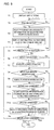
- the processor of the information processing device 5 starts the processing as shown in FIG. 4 when a command for displaying a list of items is inputted.
- the names or ID numbers specifying operation programs and associated information for the respective components of the system suitable for each kind of workpiece are read and displayed on the display device of the information processing device 5 as a list of items grouped by kind of workpiece and by component of the system, as shown in FIG. 2 (Step S1).
- the operation programs and associated information such as parameters are uploaded from the controllers of the components of the system related to the selected item to the information processing device 5 through the communication path 6 and the uploaded data are displayed on a display screen 10 of the display device in the form of a window (Steps S3, S4).
- the window 11 includes a program name indication area 11a at left above, an image display area 11b at left center, an operation program display area 11c at right center and buttons 11d for selecting data of parameters.
- a pointer indicating a position of the program in execution is displayed to indicate a progress of execution of the program.
- the processor repeatedly determines whether or not there is another item selected (Step S5), any manual input for editing (Step S6), any manual input for window modification (Step S8), an download command inputted (Step S10), and a termination command inputted (Step S12).
- Step S5 the procedure returns to Step S3 and the processing of Steps S3 and S4 is executed to display the information regarding the selected item.
- the item "PNS001" for the handling robot with respect to a kind of workpice "K1" as indicated by fine dots in FIG. 2 a window 12 having a program name indicating area 12a indicating "PNS0001" and a program display area 12b displaying the contents of the operation program is displayed on the display screen.
- the window 12 is also provided with an area 12c providing buttons for selecting the other kinds of workpieces and an area 12c providing buttons for selecting data of parameters to be displayed.
- the item "RIGHT” for the jig device 2 or the item “LX20" for the machine tool 1 with respect to the workpiece of the kind "K1" is selected, the operation program and associated information for the controller for the jig device or the machining program and associated information for the controller of the machine tool 1 are displayed on the display screen in the form of window.
- the displayed window if one of the buttons 11d, 12d for selecting associated information is selected by the operator, the parameters of the associated information are displayed.
- the operation programs and the associated information such as parameters for the machine tool 1, the jig device 2, the handling robot 3 and the visual sensor 4 for use in machining of the workpiece of the kind "K1" are displayed on the same display screen simultaneously.
- Step S6 the processor executes processing for the editing.
- Step S8 when it is determined that manual operation on the data input device for modifying the window on the display screen such as enlargement, contraction and movement (Step S8), the processor performed processing for the required modification (Step S9).
- Step S10 After the editing of the operation programs and/or the associated parameters is finished, when a command to download the edited operation program and/or the associated parameters is inputted (Step S10), the edited operation program and/or the associated parameters are downloaded to the controller of the associated component of the system through the communication path 6 (Step S11). For example, as shown in FIG. 2, in the case where the item "PNS0001" for the handling robot is selected and the operation program specified by the item "PNS0001" is displayed, when a download command for the "PNS0001" is inputted, the displayed operation program is downloaded to the controller of the handling robot 3 and stored therein to be rewritten.
- Step S12 If it is determined that a termination command is inputted (Step S12), the procedure is terminated.
- editing of the operation programs and the associated information such as parameters is carried out by the information processing device 5 and the edited operation programs and the associated information are downloaded to the respective apparatuses 1-4 to update the operation programs and the associated information stored in the respective components, to make the management of the machining process easy.
- the operation programs and the associated information are stored in the respective components 1-4 of the system.
- the operation programs and the associated information for the respective components of the system with respect to the kinds of workpieces may be stored in the information processing device 5, so that the operation programs and the associated information specified by a selected item are downloaded to the respective components of the system.
- FIG. 5 shows processing for the information management in the case where the operation programs and the associated information for the respective components of the system are stored in the information processing device . This processing differs from the processing shown in FIG. 4 in Steps T3, T11-T13.
- a command to display a list of items, a list of operation programs for the respective components of the system with respect to the kinds of workpieces is displayed on the display screen 10 of the information processing device 5, as shown in FIG. 2 (Step T1).
- the operation program and the associated information such as parameters for the selected item are read from the storage device in the information processing device 5 and displayed on the display screen 10 of the display device in the form of window (Steps T3, T4).
- This processing is different from that in the processing shown in FIG. 4 in that the program and the associated information are read from the storage device of the information processing device 5.
- a window including the operation program and an image of a sample workpiece of the kind "K1" as the associated information for the visual sensor 4 suitable for the machining of the workpiece of the kind "K1” is displayed.
- the name of the operation program is indicated in a name indication area 11a
- the image of the sample workpiece is displayed in the image display area 11b
- contents of the operation program is displayed in a program display area 11c
- the associated information selection buttons are displayed in the area 11d.
- the processor repeatedly determines whether or not there is another item selected (Step T5), any manual input for editing (Step T6), any manual input for window modification (Step T8), a download command inputted (Step T10), an upload command inputted (Step T12), and a termination command inputted (Step S12). If it is determined that another item is selected from the list (Step T5), the procedure returns to Step T3 to perform the processing of Steps T3 and T4 to display the information on the selected item.
- a window 12 having the program name area 12a indicating the name of the program, the program display area 12b displaying the robot operation program, the area 12c displaying the buttons for selecting other kinds of workpieces, and the area 12d displaying buttons for selecting the associated information is displayed on the display screen 10, as shown in FIG. 3.
- the item "RIGHT” for the jig device 2 or the item “LX20" for the machine tool 1 with respect to the workpiece of the kind "K1" is selected, the operation program and associated information for the controller for a jig device or the machining program and associated information for the controller of the machine tool 1 are displayed on the display screen in the form of window.
- the displayed window if one of the buttons 11d, 12d for selecting associated information is selected by the operator, the parameters of the associated information are displayed.
- the operation programs and the associated information such as parameters for the machine tool 1, the jig device 2, the handling robot 3 and the visual sensor 4 for use in machining of the workpiece of the kind "K1" are displayed on the same display screen simultaneously.
- Step T6 the processor executes processing for the editing.
- Step T8 when it is determined that manual operation on the data input device for modifying the window on the display screen such as enlargement, contraction and movement (Step T8), the processor performed processing for the required modification (Step T9).
- Step T10 After the editing of the operation programs and/or the associated parameters is finished, when a command to download the edited operation program and/or the associated parameters is inputted (Step T10), the edited operation program and/or the associated parameters are downloaded to the controller of the related component of the system through the communication path 6, and also stored in the storage device of the information processing device 5 to be rewritten and updated (Step T11).
- Step T 10 when one of the kinds of workpieces is selected and a command for download is inputted (Step T 10), the operation programs and the associated information for the respective components with respect to the selected kind of workpiece are read from the storage device and downloaded to the respective components of the system.
- the processing shown in FIG. 5 differs from the processing shown in FIG. 4 in that the operation programs and the associated information are downloaded to the respective components of the system at a time, and that the operation programs and the associated information are stored in the storage device of the information processing device 5 to be rewritten to update the original operation programs and the associated information, as well as downloaded to the respective components of the system.
- Step T12 When one of the components of the machine tool, the jig device, the handling robot and the visual sensor is selected in the list as shown in FIG. 2 and an upload command is inputted (Step T12), the operation program and the associated information in execution for the selected component are uploaded and displayed on the display screen 10 in the form of a window and the progress status of execution of the operation program is indicated by a pointer (Step T13).
- Step T12 When it is determined that a termination command is inputted (Step T12), the procedure is terminated.
- the operation programs and the associated information for the respective components of the machining system can be confirmed and edited using only the information processing device 5, and a group of the operation programs and the associated information for the respective components with respect to each kind of workpiece are displayed on the same display screen 10 simultaneously for confirmation and editing thereof. Further, when the operation programs are in execution, progress statuses of execution of the operation programs are displayed to be monitored.
- the information processing device 5 is provided separately from the controllers of the visual sensor 4, the handling robot 3, the jig device 2 and the machine tool 1.
- one of the controllers of the visual sensor 4, the handling robot, the jig device 2 and the machine tool 1 may be used to perform the function of the information processing device 5.
- the items of names or ID numbers specifying the operation programs and the associated information for the respective components of the system are displayed as a list.
- the names or ID numbers of the operation programs and the names or ID numbers of the associated information may be separately displayed on the display screen.
- the operation programs and the associated information for the respective components of the machining system which cooperate with one another, can be confirmed, created and edited at one place by an operator, to improve efficiency of management of the machining system.
- the operation programs and the associated information for the components of the system are simultaneously displayed on the same display screen to allow the operator to confirm relations among the components and present status of the operations of the respective components of the system.
Landscapes
- Engineering & Computer Science (AREA)
- General Engineering & Computer Science (AREA)
- Manufacturing & Machinery (AREA)
- Quality & Reliability (AREA)
- Physics & Mathematics (AREA)
- General Physics & Mathematics (AREA)
- Automation & Control Theory (AREA)
- Numerical Control (AREA)
- Manipulator (AREA)
- General Factory Administration (AREA)
Abstract
Description
Claims (7)
- A machining system for machining workpieces of different kinds, comprising:wherein the operation program and/or the associated information specified by the item selected by the operator can be displayed on the display screen to allow the operator to confirm and/or edit the displayed operation program and/or associated information.a machine tool for performing machining on a workpiece;a handling robot for handling the workpiece; anda visual sensor for detecting the workpiece;
with an information processing device being cooperable between said machine tool, said handling robot and said visual sensor through a communication path,said information processing device including display means for displaying items specifying operation programs for said machine tool, said handling robot or said visual sensor to be used for different kinds of workpieces on a display screen; andcommunicating means for uploading/downloading an operation program specified by one of the items displayed on the display screen selected by an operator and/or information associated with the operation program from /to said machine tool, said handling robot and/or said visual sensor, - A machining system according to claim 1, wherein said information processing device further includes editing means for editing the operation program and/or the associated information displayed on the display screen.
- A machining system according to claim 1 or 2, wherein said associated information includes parameters for executing the operation program.
- A machining system according to claim 1, 2 or 3, wherein said display means can simultaneously display information on a plurality of operation programs specified by items selected by the operator on the display screen.
- A machining system according to any preceding claim,
wherein said display means can simultaneously display the operation programs and/or the associated information for at least two of said machine tool, said handling robot and said visual sensor on the display screen. - A machining system according to any preceding claim,
wherein one of said machine tool, said handling robot and said visual sensor functions as said information processing device. - A machining system according to any preceding claim,
wherein said display means can display said items in a list.
Applications Claiming Priority (2)
| Application Number | Priority Date | Filing Date | Title |
|---|---|---|---|
| JP2002243544 | 2002-08-23 | ||
| JP2002243544A JP3691032B2 (en) | 2002-08-23 | 2002-08-23 | Processing equipment |
Publications (3)
| Publication Number | Publication Date |
|---|---|
| EP1391795A2 true EP1391795A2 (en) | 2004-02-25 |
| EP1391795A3 EP1391795A3 (en) | 2004-04-07 |
| EP1391795B1 EP1391795B1 (en) | 2007-04-11 |
Family
ID=31185235
Family Applications (1)
| Application Number | Title | Priority Date | Filing Date |
|---|---|---|---|
| EP03254998A Expired - Lifetime EP1391795B1 (en) | 2002-08-23 | 2003-08-12 | Machining system |
Country Status (7)
| Country | Link |
|---|---|
| US (1) | US7035711B2 (en) |
| EP (1) | EP1391795B1 (en) |
| JP (1) | JP3691032B2 (en) |
| KR (1) | KR100556173B1 (en) |
| CN (1) | CN1268996C (en) |
| DE (1) | DE60313090T2 (en) |
| TW (1) | TWI225578B (en) |
Cited By (1)
| Publication number | Priority date | Publication date | Assignee | Title |
|---|---|---|---|---|
| EP1815301B1 (en) | 2004-11-26 | 2015-07-22 | ABB Research Ltd. | A system and a method for controlling movements of an industrial robot |
Families Citing this family (28)
| Publication number | Priority date | Publication date | Assignee | Title |
|---|---|---|---|---|
| US20070198057A1 (en) * | 2006-02-21 | 2007-08-23 | Daniel Gelbart | Method and device for closing holes in tissue |
| ATE497197T1 (en) * | 2006-03-29 | 2011-02-15 | Siemens Ag | FIELD DEVICE |
| JP4235214B2 (en) * | 2006-07-04 | 2009-03-11 | ファナック株式会社 | Apparatus, program, recording medium, and method for creating robot program |
| JP5215574B2 (en) * | 2007-03-08 | 2013-06-19 | カヤバ工業株式会社 | Production line management system |
| JP5152488B2 (en) * | 2007-11-30 | 2013-02-27 | 豊和工業株式会社 | Work machine motion control device |
| JP4598865B2 (en) * | 2009-02-17 | 2010-12-15 | ファナック株式会社 | Robot control device used in combination with machine tools |
| US9119655B2 (en) | 2012-08-03 | 2015-09-01 | Stryker Corporation | Surgical manipulator capable of controlling a surgical instrument in multiple modes |
| US9921712B2 (en) | 2010-12-29 | 2018-03-20 | Mako Surgical Corp. | System and method for providing substantially stable control of a surgical tool |
| CN119097419A (en) | 2012-08-03 | 2024-12-10 | 史赛克公司 | Systems and methods for robotic surgery |
| US9820818B2 (en) | 2012-08-03 | 2017-11-21 | Stryker Corporation | System and method for controlling a surgical manipulator based on implant parameters |
| US9226796B2 (en) | 2012-08-03 | 2016-01-05 | Stryker Corporation | Method for detecting a disturbance as an energy applicator of a surgical instrument traverses a cutting path |
| JPWO2014068667A1 (en) * | 2012-10-30 | 2016-09-08 | 株式会社牧野フライス製作所 | Machining program creation method and apparatus |
| US20140259670A1 (en) * | 2013-03-18 | 2014-09-18 | Factory Automation Technology Co., Ltd. | Human-Machine Interface Mechanism For Automated Wheel Production |
| JP6331732B2 (en) * | 2014-06-09 | 2018-05-30 | 日産自動車株式会社 | JIG DEVICE, OPERATION SYSTEM, AND JIG DEVICE OPERATION METHOD |
| JP6514041B2 (en) * | 2015-06-02 | 2019-05-15 | 株式会社ミツトヨ | Control method of shape measuring device |
| JP6250901B2 (en) | 2015-10-28 | 2017-12-20 | ファナック株式会社 | A robot system in which a CNC and a robot controller are connected via a communication network |
| JP6638519B2 (en) * | 2016-03-30 | 2020-01-29 | 三菱自動車エンジニアリング株式会社 | Production line development support device, development support method, and development support program |
| EP3554414A1 (en) | 2016-12-16 | 2019-10-23 | MAKO Surgical Corp. | Techniques for modifying tool operation in a surgical robotic system based on comparing actual and commanded states of the tool relative to a surgical site |
| JP6538771B2 (en) | 2017-07-26 | 2019-07-03 | ファナック株式会社 | Numerical control device and control method of numerical control device |
| JP6871218B2 (en) * | 2018-10-12 | 2021-05-12 | ファナック株式会社 | Machining information recording device, machining information recording method and program |
| JP7409852B2 (en) * | 2019-12-10 | 2024-01-09 | ファナック株式会社 | robot control device |
| US12416483B2 (en) | 2021-11-24 | 2025-09-16 | Hexagon Metrology, Inc. | Parametric and modal work-holding apparatus |
| US12066808B2 (en) * | 2021-11-24 | 2024-08-20 | Hexagon Metrology, Inc. | Parametric and modal work-holding method for automated inspection |
| US12343860B2 (en) * | 2021-11-24 | 2025-07-01 | Hexagon Metrology, Inc. | Automated work-holding for precise fastening of light parts during automated transfer |
| EP4619204A1 (en) * | 2022-11-15 | 2025-09-24 | Hexagon Metrology, Inc. | Parametric and modal work-holding apparatus |
| WO2024232024A1 (en) * | 2023-05-09 | 2024-11-14 | ファナック株式会社 | Machining information display device |
| WO2024232022A1 (en) * | 2023-05-09 | 2024-11-14 | ファナック株式会社 | Machining information display device |
| JP7415094B1 (en) * | 2023-05-09 | 2024-01-16 | ファナック株式会社 | Processing information display device |
Family Cites Families (20)
| Publication number | Priority date | Publication date | Assignee | Title |
|---|---|---|---|---|
| JPS5822411A (en) | 1981-08-04 | 1983-02-09 | Fanuc Ltd | Industrial robot control system |
| US4998206A (en) | 1988-07-29 | 1991-03-05 | The Boeing Company | Automated method and apparatus for fabricating sheet metal parts and the like using multiple manufacturing stations |
| US5220718A (en) | 1986-12-05 | 1993-06-22 | Gemcor Engineering Corp. | Programmable fixture and assembly cell |
| US4894908A (en) * | 1987-08-20 | 1990-01-23 | Gmf Robotics Corporation | Method for automated assembly of assemblies such as automotive assemblies and system utilizing same |
| US5050088A (en) | 1989-03-29 | 1991-09-17 | Eastman Kodak Company | Production control system and method |
| JPH05228866A (en) | 1991-05-14 | 1993-09-07 | Canon Inc | Controller of automatic holding device in use of visual sense |
| JP3211422B2 (en) | 1992-11-11 | 2001-09-25 | ブラザー工業株式会社 | Robot controller |
| GB2281779B (en) * | 1993-09-14 | 1997-04-23 | Rank Taylor Hobson Ltd | Metrological instrument |
| EP0744046B1 (en) * | 1994-11-09 | 2003-02-12 | Amada Company Limited | Intelligent system for generating and executing a sheet metal bending plan |
| US5969973A (en) * | 1994-11-09 | 1999-10-19 | Amada Company, Ltd. | Intelligent system for generating and executing a sheet metal bending plan |
| US5761940A (en) * | 1994-11-09 | 1998-06-09 | Amada Company, Ltd. | Methods and apparatuses for backgaging and sensor-based control of bending operations |
| US5896292A (en) * | 1995-06-05 | 1999-04-20 | Canon Kabushiki Kaisha | Automated system for production facility |
| JP3683616B2 (en) * | 1995-06-23 | 2005-08-17 | 株式会社アマダ | Processing program selection device in sheet metal processing system |
| JPH1097313A (en) * | 1996-09-19 | 1998-04-14 | Toshiba Mach Co Ltd | Factory automation system |
| US5883803A (en) * | 1996-09-24 | 1999-03-16 | The Regents Of The University Of California | Six degree of freedom sensor |
| US6349237B1 (en) * | 1997-12-23 | 2002-02-19 | The Regents Of The University Of Michigan | Reconfigurable manufacturing system having a production capacity method for designing same and method for changing its production capacity |
| JP2000222015A (en) * | 1999-02-01 | 2000-08-11 | Brother Ind Ltd | Numerical control unit |
| JP2001121461A (en) * | 1999-10-26 | 2001-05-08 | Denso Corp | Robot system |
| US6571148B1 (en) * | 2000-05-03 | 2003-05-27 | The Boeing Company | System for automatically certifying the accuracy of a manufacturing machine and associated methods |
| DE10032096A1 (en) * | 2000-07-01 | 2002-01-24 | Kuka Roboter Gmbh | Device network and control cabinet for such |
-
2002
- 2002-08-23 JP JP2002243544A patent/JP3691032B2/en not_active Expired - Fee Related
-
2003
- 2003-07-24 TW TW092120181A patent/TWI225578B/en not_active IP Right Cessation
- 2003-07-28 US US10/627,689 patent/US7035711B2/en not_active Expired - Fee Related
- 2003-08-12 EP EP03254998A patent/EP1391795B1/en not_active Expired - Lifetime
- 2003-08-12 DE DE60313090T patent/DE60313090T2/en not_active Expired - Fee Related
- 2003-08-22 KR KR1020030058113A patent/KR100556173B1/en not_active Expired - Fee Related
- 2003-08-25 CN CNB031558569A patent/CN1268996C/en not_active Expired - Fee Related
Cited By (1)
| Publication number | Priority date | Publication date | Assignee | Title |
|---|---|---|---|---|
| EP1815301B1 (en) | 2004-11-26 | 2015-07-22 | ABB Research Ltd. | A system and a method for controlling movements of an industrial robot |
Also Published As
| Publication number | Publication date |
|---|---|
| KR20040018197A (en) | 2004-03-02 |
| TWI225578B (en) | 2004-12-21 |
| CN1489013A (en) | 2004-04-14 |
| JP3691032B2 (en) | 2005-08-31 |
| US20040039484A1 (en) | 2004-02-26 |
| EP1391795B1 (en) | 2007-04-11 |
| DE60313090D1 (en) | 2007-05-24 |
| CN1268996C (en) | 2006-08-09 |
| DE60313090T2 (en) | 2007-07-19 |
| JP2004086311A (en) | 2004-03-18 |
| EP1391795A3 (en) | 2004-04-07 |
| US7035711B2 (en) | 2006-04-25 |
| TW200403553A (en) | 2004-03-01 |
| KR100556173B1 (en) | 2006-03-03 |
Similar Documents
| Publication | Publication Date | Title |
|---|---|---|
| US7035711B2 (en) | Machining system | |
| EP2081096B1 (en) | Controller of work piece-conveying robot | |
| US8155789B2 (en) | Device, method, program and recording medium for robot offline programming | |
| EP0780197A1 (en) | Apparatus for controlling movement of robot and method of controlling movement of robot | |
| CN110737244B (en) | Numerical control device and data editing method | |
| JP2019171498A (en) | Robot program execution device, robot program execution method and program | |
| CN110682288A (en) | Robot program generating device | |
| CN113021335A (en) | Robot teaching device with icon programming function | |
| EP1616674A2 (en) | Robot system provided with robot controller | |
| US5997169A (en) | Control apparatus for manufacturing system and method of controlling therefor | |
| JPH08286722A (en) | Method and system for off-line teaching using CAD data | |
| EP0573657B1 (en) | Robot controller | |
| EP0075325B1 (en) | Control apparatus and method for industrial robot | |
| JP3378738B2 (en) | Welding robot teaching device | |
| JP6824454B1 (en) | Machine tools, machine tools, and control programs | |
| KR101610386B1 (en) | Cutting shape input apparatus and method using cutting program in computer numarical control machine tools | |
| JP7856835B1 (en) | Control device, design support method, and design support program | |
| US20250262766A1 (en) | Robot programming device and programming method | |
| JPH06270082A (en) | Control of robot having auxiliary shaft | |
| JP2886289B2 (en) | FMS work input / recovery method | |
| JP7024795B2 (en) | Robot teaching device | |
| JP2025184068A (en) | ROBOT DEVICE, CONTROL METHOD, AND PROGRAM | |
| US20230072717A1 (en) | Display control system | |
| JP7099470B2 (en) | Robot teaching device | |
| JP4774683B2 (en) | Support device for servo controller |
Legal Events
| Date | Code | Title | Description |
|---|---|---|---|
| PUAI | Public reference made under article 153(3) epc to a published international application that has entered the european phase |
Free format text: ORIGINAL CODE: 0009012 |
|
| PUAL | Search report despatched |
Free format text: ORIGINAL CODE: 0009013 |
|
| AK | Designated contracting states |
Kind code of ref document: A2 Designated state(s): AT BE BG CH CY CZ DE DK EE ES FI FR GB GR HU IE IT LI LU MC NL PT RO SE SI SK TR |
|
| AX | Request for extension of the european patent |
Extension state: AL LT LV MK |
|
| AK | Designated contracting states |
Kind code of ref document: A3 Designated state(s): AT BE BG CH CY CZ DE DK EE ES FI FR GB GR HU IE IT LI LU MC NL PT RO SE SI SK TR |
|
| AX | Request for extension of the european patent |
Extension state: AL LT LV MK |
|
| RIC1 | Information provided on ipc code assigned before grant |
Ipc: 7G 05B 19/418 A |
|
| 17P | Request for examination filed |
Effective date: 20040823 |
|
| AKX | Designation fees paid |
Designated state(s): DE |
|
| 17Q | First examination report despatched |
Effective date: 20041126 |
|
| GRAP | Despatch of communication of intention to grant a patent |
Free format text: ORIGINAL CODE: EPIDOSNIGR1 |
|
| GRAS | Grant fee paid |
Free format text: ORIGINAL CODE: EPIDOSNIGR3 |
|
| GRAA | (expected) grant |
Free format text: ORIGINAL CODE: 0009210 |
|
| AK | Designated contracting states |
Kind code of ref document: B1 Designated state(s): DE |
|
| REF | Corresponds to: |
Ref document number: 60313090 Country of ref document: DE Date of ref document: 20070524 Kind code of ref document: P |
|
| PLBE | No opposition filed within time limit |
Free format text: ORIGINAL CODE: 0009261 |
|
| STAA | Information on the status of an ep patent application or granted ep patent |
Free format text: STATUS: NO OPPOSITION FILED WITHIN TIME LIMIT |
|
| 26N | No opposition filed |
Effective date: 20080114 |
|
| PGFP | Annual fee paid to national office [announced via postgrant information from national office to epo] |
Ref country code: DE Payment date: 20080908 Year of fee payment: 6 |
|
| PG25 | Lapsed in a contracting state [announced via postgrant information from national office to epo] |
Ref country code: DE Free format text: LAPSE BECAUSE OF NON-PAYMENT OF DUE FEES Effective date: 20100302 |