EP1391769A2 - A steerable night vision system - Google Patents
A steerable night vision system Download PDFInfo
- Publication number
- EP1391769A2 EP1391769A2 EP03102547A EP03102547A EP1391769A2 EP 1391769 A2 EP1391769 A2 EP 1391769A2 EP 03102547 A EP03102547 A EP 03102547A EP 03102547 A EP03102547 A EP 03102547A EP 1391769 A2 EP1391769 A2 EP 1391769A2
- Authority
- EP
- European Patent Office
- Prior art keywords
- vehicle
- camera
- night vision
- image
- signal
- Prior art date
- Legal status (The legal status is an assumption and is not a legal conclusion. Google has not performed a legal analysis and makes no representation as to the accuracy of the status listed.)
- Withdrawn
Links
Images

Classifications
-
- G—PHYSICS
- G02—OPTICS
- G02B—OPTICAL ELEMENTS, SYSTEMS OR APPARATUS
- G02B23/00—Telescopes, e.g. binoculars; Periscopes; Instruments for viewing the inside of hollow bodies; Viewfinders; Optical aiming or sighting devices
- G02B23/12—Telescopes, e.g. binoculars; Periscopes; Instruments for viewing the inside of hollow bodies; Viewfinders; Optical aiming or sighting devices with means for image conversion or intensification
-
- H—ELECTRICITY
- H04—ELECTRIC COMMUNICATION TECHNIQUE
- H04N—PICTORIAL COMMUNICATION, e.g. TELEVISION
- H04N23/00—Cameras or camera modules comprising electronic image sensors; Control thereof
- H04N23/60—Control of cameras or camera modules
- H04N23/66—Remote control of cameras or camera parts, e.g. by remote control devices
-
- B—PERFORMING OPERATIONS; TRANSPORTING
- B60—VEHICLES IN GENERAL
- B60Q—ARRANGEMENT OF SIGNALLING OR LIGHTING DEVICES, THE MOUNTING OR SUPPORTING THEREOF OR CIRCUITS THEREFOR, FOR VEHICLES IN GENERAL
- B60Q2300/00—Indexing codes for automatically adjustable headlamps or automatically dimmable headlamps
- B60Q2300/10—Indexing codes relating to particular vehicle conditions
- B60Q2300/12—Steering parameters
- B60Q2300/122—Steering angle
-
- B—PERFORMING OPERATIONS; TRANSPORTING
- B60—VEHICLES IN GENERAL
- B60Q—ARRANGEMENT OF SIGNALLING OR LIGHTING DEVICES, THE MOUNTING OR SUPPORTING THEREOF OR CIRCUITS THEREFOR, FOR VEHICLES IN GENERAL
- B60Q2300/00—Indexing codes for automatically adjustable headlamps or automatically dimmable headlamps
- B60Q2300/10—Indexing codes relating to particular vehicle conditions
- B60Q2300/12—Steering parameters
- B60Q2300/128—Steering dead zone
-
- B—PERFORMING OPERATIONS; TRANSPORTING
- B60—VEHICLES IN GENERAL
- B60Q—ARRANGEMENT OF SIGNALLING OR LIGHTING DEVICES, THE MOUNTING OR SUPPORTING THEREOF OR CIRCUITS THEREFOR, FOR VEHICLES IN GENERAL
- B60Q2300/00—Indexing codes for automatically adjustable headlamps or automatically dimmable headlamps
- B60Q2300/10—Indexing codes relating to particular vehicle conditions
- B60Q2300/13—Attitude of the vehicle body
- B60Q2300/132—Pitch
-
- B—PERFORMING OPERATIONS; TRANSPORTING
- B60—VEHICLES IN GENERAL
- B60Q—ARRANGEMENT OF SIGNALLING OR LIGHTING DEVICES, THE MOUNTING OR SUPPORTING THEREOF OR CIRCUITS THEREFOR, FOR VEHICLES IN GENERAL
- B60Q2300/00—Indexing codes for automatically adjustable headlamps or automatically dimmable headlamps
- B60Q2300/10—Indexing codes relating to particular vehicle conditions
- B60Q2300/13—Attitude of the vehicle body
- B60Q2300/134—Yaw
-
- B—PERFORMING OPERATIONS; TRANSPORTING
- B60—VEHICLES IN GENERAL
- B60Q—ARRANGEMENT OF SIGNALLING OR LIGHTING DEVICES, THE MOUNTING OR SUPPORTING THEREOF OR CIRCUITS THEREFOR, FOR VEHICLES IN GENERAL
- B60Q2300/00—Indexing codes for automatically adjustable headlamps or automatically dimmable headlamps
- B60Q2300/30—Indexing codes relating to the vehicle environment
- B60Q2300/32—Road surface or travel path
-
- H—ELECTRICITY
- H04—ELECTRIC COMMUNICATION TECHNIQUE
- H04N—PICTORIAL COMMUNICATION, e.g. TELEVISION
- H04N23/00—Cameras or camera modules comprising electronic image sensors; Control thereof
- H04N23/20—Cameras or camera modules comprising electronic image sensors; Control thereof for generating image signals from infrared radiation only
- H04N23/23—Cameras or camera modules comprising electronic image sensors; Control thereof for generating image signals from infrared radiation only from thermal infrared radiation
Definitions
- the present invention relates generally to a night vision system and more particularly to a night vision system that is responsive to a vehicle steering system.
- Night vision systems are utilized to allow a user to see objects at relatively low visibility light levels.
- Examples of night vision technologies are image enhancement and thermal imaging.
- Image enhancement functions through collecting the tiny amounts of light, including the near infrared light spectrum, that are present but may be imperceptible to human eyes, and amplifying the light to a point at which the image can easily be observed.
- Thermal imaging operates by capturing the far infrared light spectrum, which is emitted as heat by objects instead of simply reflected as light. Hotter objects, such as warm bodies, emit more of this light than cooler objects such as trees or buildings.
- Night vision systems typically are classified as either passive or active.
- passive, night vision systems used in automotive applications far infrared cameras are used to image objects using the ambient infrared light emitted by the objects in the environment.
- Far infrared night vision systems have relatively few pixels and, accordingly, images formed using such cameras have low video resolution and a relatively narrow field of view.
- active night vision systems utilize a near-infrared (NIR) diode laser or a filtered incandescent light source.
- NIR near-infrared
- the NIR light is subsequently reflected off objects in the environment and is received by a camera.
- the camera generates a video signal responsive to received light.
- a night vision system for a vehicle characterised in that the system comprises at least one vehicle directional sensor coupled to the vehicle and adapted to generate a vehicle directional signal when the vehicle is changing direction, a night vision camera adapted to generate a camera signal, a camera motor adapted to direct the night vision camera and a camera motor control unit adapted to receive the vehicle directional signal from the or each vehicle directional sensor and activate the camera motor in response thereto.
- the vehicle directional sensor may comprise at least one of a steering wheel position sensor, a pitch sensor, a Global Positioning System unit, a wheel sensor and an accelerometer.
- the night vision camera may be coupled to the vehicle by means of a gimbal.
- the gimbal may limit the range of motion of the night vision camera.
- the system may further comprise an image-steadying unit adapted to receive and stabilize the camera signal.
- the system may further comprise a camera image-viewing unit adapted to receive and display the camera signal.
- the image steadying unit may be operable to generate a stabilized signal.
- the camera image-viewing unit may be adapted to receive and display the stabilized signal from the camera.
- the system may further comprise a steering control unit coupled to the vehicle.
- the steering control unit may comprise the camera motor control unit.
- the vehicle directional signal may be received in both the steering control unit and the camera motor control unit.
- a night vision method for a vehicle comprising sensing that the vehicle is changing direction, generating a vehicle directional signal, activating a camera motor control unit adapted to direct a night vision camera in response to the vehicle directional signal, shifting area of view of the night vision camera, generating an image from the night vision camera corresponding to night vision camera area of view and displaying the image on an image view screen.
- Sensing that the vehicle is changing direction may comprises at least one of sensing a change in a vehicle pitch, sensing a change in a vehicle yaw and sensing a rotation of a steering wheel.
- the method may further comprise steadying an image from the night vision camera.
- Steadying an image from the night vision camera may comprise steadying the image by mounting the camera via a gimbal.
- Steadying an image from the night vision camera may comprise steadying the image with an image steadying unit.
- the present invention is illustrated with respect to a night vision system, particularly suited to the automotive field. However, the present invention is applicable to various other uses that may require night vision as will be understood by one skilled in the art.
- a camera motor control unit 18 is electrically coupled to the directional sensor 14, 27 or 29 and a camera control motor 20.
- the camera control motor 20 is coupled to a night vision camera 22, which generates a camera signal.
- the night vision camera 22 is moveably coupled to a gimbal 24 and electrically coupled to an image-steadying unit 26.
- the image-steadying unit 26 is electrically coupled to a camera image-viewing unit 28.
- Directional sensors 14, 27 and 29, which are well known in the art, generate at least one vehicle directional signal when the vehicle 22 is changing direction, as will be discussed later.
- Examples of directional sensors include wheel sensors 27, pitch sensors 29, Global Positioning System (GPS) units, head mount sensors (such as incorporated in apache helicopters), steering wheel position sensors 14, and various other sensor types and combinations thereof, as will be understood by one skilled in the art.
- GPS Global Positioning System
- the vehicle directional signal is embodied as, for example, a signal from the wheel sensors 27 generated when the wheels 36 are turning.
- An alternate vehicle directional signal is generated from a pitch sensor 29 indicating that the vehicle 12 is ascending or descending.
- Another embodiment includes a GPS system where satellite tracking directs the night vision camera when the vehicle 12 is undergoing, for example, a turn.
- Another embodiment for a directional sensor is an accelerometer.
- Still another embodiment includes a vehicle directional signal generated from a steering wheel position sensor 14 when the steering wheel is turning.
- FIGURES 1 and 2 illustrate a vehicle 12 including a wheel sensor 27, a pitch sensor 29, and a steering wheel position sensor 14. It will be apparent to one skilled in the art that the present invention includes at least one of the aforementioned sensors or a combination thereof or alternate sensors that sense vehicle turning or vehicle pitch (i.e. vehicle is changing direction) and generate therefrom a vehicle directional signal.
- the vehicle directional signal is received in both the camera motor control unit 18 and, for the steering wheel position sensor 14, in the steering control unit 30.
- the steering control unit 30 typically controls steering functions such as electric power steering.
- the camera motor control unit 18 is embodied as a computer containing logic adapted to receive the vehicle directional signal and respond by signalling the camera motor 20 to move the night vision camera 22.
- the camera motor control unit 18 responds to either the vehicle directional signal or a signal from the steering control unit 30 that signals that the vehicle 12 is undergoing a turn, ascending or descending.
- Alternate embodiments include the camera motor control unit 18 as a component of the steering control unit 30.
- the steering angle of the vehicle 12 can be obtained from any of a number of sources already incorporated in the vehicle 12.
- FIGURE 3 a perspective view of the night vision camera assembly 32, including x, y, and z-axis frames of reference, according to one embodiment of the present invention, is illustrated.
- the night vision camera 22 generates a camera signal and is coupled to a rotatable mount 34 which, in turn, is seated on a damped gimbal 24.
- Types of night vision sensors include thermal, CCD (charge-coupled device), or CMOS (complimentary metal-oxide semiconductor) cameras, as will be understood by one skilled in the art.
- the rotatable mount 34 couples the night vision camera 22 to the vehicle 12 and provides full range of motion to the night vision camera 22.
- Gimbals are a type of mount for an instrument such as a gyroscope or compass in which the instrument is free to rotate about two or three perpendicular axes.
- the gimbal 24 permits two (x and y-axis) or three (x, y and z-axis) degrees of freedom to the night vision camera 22.
- Alternate embodiments include any and all gimbal-type devices.
- the image is further controlled using stabilization software in the image-steadying unit 26 similar to that used for handheld camcorders.
- the image-steadying unit 26 receives the camera signal and stabilizes it, thereby generating a stabilized signal.
- the camera image-viewing unit 28 such as a video screen, HUD, liquid crystal display, or other device receives the stabilized signal and displays it in view of the vehicle driver.
- the driver is presented with a stable image that is pointing in the direction the vehicle 12 is heading and, more importantly, where the driver is looking not just the direction that the front end of the vehicle is pointing.
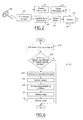
- FIGURE 4 a schematic view of the vehicle night vision system 10 of FIGURE 1 undergoing a vehicle turn operation, according to one embodiment of the present invention, is illustrated.
- the night vision camera 22 is illustrated rotating with the tires 36 through operation of the aforementioned camera motor control unit 18.
- FIGURE 5 a schematic view of a vehicle night vision system 40 according to another embodiment of the present invention is illustrated. Alternate placements of the night vision camera on the vehicle 49 are illustrated. For example, a single night vision camera 42 is shown located within a conventional vehicle rear-view mirror housing 44. Alternately, two night vision cameras 46 are located within each of the side mirrors 47, 48. The night vision camera is either pointed in the direction of vehicle travel, or alternately in the direction opposite the vehicle direction of travel and receiving the image received by each of the respective mirrors.
- the directional sensor such as the steering wheel position sensor 50 senses change in position of the steering wheel 52 and therefrom generates a vehicle directional signal.
- the camera motor control unit 54 receives the vehicle directional signal from the steering wheel position sensor 50 and activates the camera motor 56, which directs the night vision camera or cameras 42, 46.
- the night vision cameras 42, 46 are coupled to gimbals and an image-steadying unit 58.
- the gimbal is coupled to the vehicle 49, and an image is presented on an image viewing unit as was previously discussed regarding FIGURE 1.
- the night vision camera or plurality of night vision cameras 42, 46 are positioned almost anywhere on the vehicle 49, however, the aforementioned locations are preferred.
- Alternate embodiments include the camera motor control unit 54 electrically coupled to the steering control unit 59.
- the steering angle of the vehicle can be obtained from any of a number of sources already incorporated in the vehicle 12.
- Logic starts in operation block 60 where either the yaw or pitch of the vehicle is undergoing a noticeable change and a vehicle directional signal is generated.
- a check is then made in inquiry block 62 whether the vehicle directional signal is large enough to require camera movement. For a negative response, logic ends. This check is optional, however, in cases that just involve changing lanes, for example, the night vision camera field of view is still directed in the direction of travel.
- operation block 64 activates, and the camera motor control unit is activated.
- operation block 66 activates and the camera motor control unit directs the night vision camera.
- Operation block 68 activates and steadying software is activated to steady the image for display, which subsequently occurs in operation block 72.
- the vehicle In operation, the vehicle is travelling down a road and the driver initiates a turn or navigates a hill. This generates a vehicle directional signal that activates the camera motor control, which directs the night vision camera.
- the image from the night vision camera is steadied both by a gimbal, which the night vision camera sits upon, and an image steadying unit, which contains image steadying software.
- the image is displayed on an image view screen, and shows a relatively continuous transition from one direction of vehicle travel, through a turn, and to another direction of vehicle travel.
- the present invention enhances the utility of night vision systems far beyond present ranges of use by providing added night vision information during various vehicle operating conditions such as when the vehicle is changing direction due to changing bearing ,undergoing a turn, ascending or descending.
- the aforementioned system directs the night vision camera while the vehicle is turning rather than having a constant view along the instantaneous direction of travel of the vehicle, as currently exists in the art.
Landscapes
- Physics & Mathematics (AREA)
- Astronomy & Astrophysics (AREA)
- General Physics & Mathematics (AREA)
- Optics & Photonics (AREA)
- Engineering & Computer Science (AREA)
- Multimedia (AREA)
- Signal Processing (AREA)
- Studio Devices (AREA)
- Closed-Circuit Television Systems (AREA)
- Fittings On The Vehicle Exterior For Carrying Loads, And Devices For Holding Or Mounting Articles (AREA)
Abstract
Description
Claims (10)
- A night vision system (10, 40) for a vehicle (12, 49) characterised in that the system (10, 40) comprises at least one vehicle directional sensor (14, 27, 29, 50) coupled to the vehicle (12, 49) and adapted to generate a vehicle directional signal when the vehicle (12, 49) is changing direction, a night vision camera (22, 42, 46) adapted to generate a camera signal, a camera motor (20, 56) adapted to direct the night vision camera (22, 42,46) and a camera motor control unit (18, 54) adapted to receive the vehicle directional signal from the or each vehicle directional sensor (14, 27, 29, 50) and activate the camera motor (20, 56) in response thereto.
- A system as claimed in claim 1 wherein the vehicle directional sensor comprises at least one of a steering wheel position sensor (14, 50), a pitch sensor (29), a Global Positioning System unit, a wheel sensor (27) and an accelerometer.
- A system as claimed in claim 1 or in claim 2 wherein the night vision camera is coupled to the vehicle by means of a gimbal (24).
- A system as claimed in any of claims 1 to 3 wherein the system further comprises an image-steadying unit (26, 58) adapted to receive and stabilize the camera signal.
- A system as claimed in any of claims 1 to 4 wherein the system further comprises a camera image-viewing unit (28) adapted to receive and display the camera signal.
- A system as claimed in any of claims 1 to 5 wherein the system further comprises a steering control unit (30) coupled to the vehicle (12).
- A system as claimed in claim 6 wherein the vehicle directional signal is received in both the steering control unit (30) and the camera motor control unit (18).
- A night vision method for a vehicle (12, 49) characterised in that the method comprises sensing that the vehicle (12, 49) is changing direction, generating a vehicle directional signal, activating a camera motor control unit (18, 54) adapted to direct a night vision camera (22, 42, 46) in response to the vehicle directional signal, shifting area of view of the night vision camera (22, 42, 46), generating an image from the night vision camera (22, 42, 46) corresponding to night vision camera area of view and displaying the image on an image view screen (28).
- A method as claimed in claim 8 wherein sensing that the vehicle is changing direction comprises at least one of sensing a change in a vehicle pitch, sensing a change in a vehicle yaw and sensing a rotation of a steering wheel.
- A method as claimed in claim 9 wherein the method further comprises steadying an image from the night vision camera.
Applications Claiming Priority (2)
| Application Number | Priority Date | Filing Date | Title |
|---|---|---|---|
| US64802 | 2002-08-19 | ||
| US10/064,802 US6725139B2 (en) | 2002-08-19 | 2002-08-19 | Steerable night vision system |
Publications (2)
| Publication Number | Publication Date |
|---|---|
| EP1391769A2 true EP1391769A2 (en) | 2004-02-25 |
| EP1391769A3 EP1391769A3 (en) | 2004-03-17 |
Family
ID=31186037
Family Applications (1)
| Application Number | Title | Priority Date | Filing Date |
|---|---|---|---|
| EP03102547A Withdrawn EP1391769A3 (en) | 2002-08-19 | 2003-08-14 | A steerable night vision system |
Country Status (2)
| Country | Link |
|---|---|
| US (1) | US6725139B2 (en) |
| EP (1) | EP1391769A3 (en) |
Cited By (3)
| Publication number | Priority date | Publication date | Assignee | Title |
|---|---|---|---|---|
| DE102005030838A1 (en) * | 2005-07-01 | 2007-01-04 | Siemens Ag | Night Vision System |
| DE102006020023A1 (en) * | 2006-01-09 | 2007-07-12 | Industrial Technology Research Institute, Chutung | Assistance monitoring device and method for controlling the same |
| FR2995096A1 (en) * | 2012-08-28 | 2014-03-07 | Jean Marc Anziani | Device for using mini on-board camera on roof of vehicle for capturing image of e.g. object, has housing arranged with rotary arm, and on-board camera fixed at end of rotary arm, where housing is fixed on roof of vehicle by magnetic plate |
Families Citing this family (13)
| Publication number | Priority date | Publication date | Assignee | Title |
|---|---|---|---|---|
| US10361802B1 (en) | 1999-02-01 | 2019-07-23 | Blanding Hovenweep, Llc | Adaptive pattern recognition based control system and method |
| US8352400B2 (en) | 1991-12-23 | 2013-01-08 | Hoffberg Steven M | Adaptive pattern recognition based controller apparatus and method and human-factored interface therefore |
| US7202776B2 (en) * | 1997-10-22 | 2007-04-10 | Intelligent Technologies International, Inc. | Method and system for detecting objects external to a vehicle |
| US8060308B2 (en) * | 1997-10-22 | 2011-11-15 | Intelligent Technologies International, Inc. | Weather monitoring techniques |
| US7983802B2 (en) * | 1997-10-22 | 2011-07-19 | Intelligent Technologies International, Inc. | Vehicular environment scanning techniques |
| US7966078B2 (en) | 1999-02-01 | 2011-06-21 | Steven Hoffberg | Network media appliance system and method |
| JP2004328399A (en) * | 2003-04-24 | 2004-11-18 | Denso Corp | In-vehicle camera device |
| US20060098448A1 (en) * | 2004-11-06 | 2006-05-11 | Mark Coast | Multiple spectrum marker and light assembly for vehicles |
| US20070233361A1 (en) * | 2006-03-30 | 2007-10-04 | Ford Global Technologies, Llc | Centralized Image Processing For An Automobile With A Navigation System |
| CN202463699U (en) * | 2012-02-09 | 2012-10-03 | 广州飒特红外股份有限公司 | Vehicle-mounted auxiliary infrared night driving system |
| CN104149701B (en) * | 2014-08-28 | 2016-02-24 | 吉林大学 | Non-blind zone automobile--Radar Control System |
| KR101822890B1 (en) * | 2015-01-22 | 2018-01-29 | 엘지전자 주식회사 | Front Vedeo Camera for Vehicles |
| US20170225628A1 (en) * | 2016-02-09 | 2017-08-10 | Ford Global Technologies, Llc | Motorized Camera Mount |
Family Cites Families (13)
| Publication number | Priority date | Publication date | Assignee | Title |
|---|---|---|---|---|
| GB178234A (en) * | 1921-01-26 | 1922-04-20 | Samuel Vernon Gramlich | Improvements in and relating to electric lighting systems for vehicles |
| US3641261A (en) * | 1969-06-04 | 1972-02-08 | Hughes Aircraft Co | Night vision system |
| US4645320A (en) | 1985-12-20 | 1987-02-24 | General Motors Corporation | Camera mount for motor vehicle |
| JPS62155140A (en) | 1985-12-27 | 1987-07-10 | Aisin Warner Ltd | Road image input system for controlling vehicle |
| EP0488828B1 (en) * | 1990-11-30 | 1996-08-14 | Honda Giken Kogyo Kabushiki Kaisha | Control device of an autonomously moving body and evaluation method for data thereof |
| JP2783079B2 (en) * | 1992-08-28 | 1998-08-06 | トヨタ自動車株式会社 | Light distribution control device for headlamp |
| US5729016A (en) * | 1994-04-12 | 1998-03-17 | Hughes Aircraft Company | Low cost night vision system for nonmilitary surface vehicles |
| JPH0995194A (en) | 1995-09-29 | 1997-04-08 | Aisin Seiki Co Ltd | Object detection device in front of the vehicle |
| KR100270523B1 (en) | 1995-12-27 | 2000-11-01 | 정몽규 | Unmanned car having control function according to the road condition |
| JP2000225970A (en) * | 1998-11-30 | 2000-08-15 | Tuner Kk | Image recording system loaded on vehicle |
| US6593848B1 (en) * | 2000-02-23 | 2003-07-15 | Atkins, Iii William T. | Motor vehicle recorder system |
| WO2002038414A1 (en) * | 2000-11-08 | 2002-05-16 | Petr Holy | Moveable front lighting system in response to the curvature of a vehicle´s trajectory. |
| JP4815677B2 (en) * | 2001-02-20 | 2011-11-16 | ソニー株式会社 | Automotive video camera system and automotive outside mirror |
-
2002
- 2002-08-19 US US10/064,802 patent/US6725139B2/en not_active Expired - Lifetime
-
2003
- 2003-08-14 EP EP03102547A patent/EP1391769A3/en not_active Withdrawn
Cited By (6)
| Publication number | Priority date | Publication date | Assignee | Title |
|---|---|---|---|---|
| DE102005030838A1 (en) * | 2005-07-01 | 2007-01-04 | Siemens Ag | Night Vision System |
| WO2007003463A1 (en) * | 2005-07-01 | 2007-01-11 | Siemens Vdo Automotive Ag | Night vision system |
| US8878932B2 (en) | 2005-07-01 | 2014-11-04 | Continental Automotive Gmbh | System and method for detecting the surrounding environment of a motor vehicle using as adjustable infrared night vision system |
| DE102006020023A1 (en) * | 2006-01-09 | 2007-07-12 | Industrial Technology Research Institute, Chutung | Assistance monitoring device and method for controlling the same |
| DE102006020023B4 (en) * | 2006-01-09 | 2008-08-28 | Industrial Technology Research Institute, Chutung | Assistance monitoring device and method for controlling the same |
| FR2995096A1 (en) * | 2012-08-28 | 2014-03-07 | Jean Marc Anziani | Device for using mini on-board camera on roof of vehicle for capturing image of e.g. object, has housing arranged with rotary arm, and on-board camera fixed at end of rotary arm, where housing is fixed on roof of vehicle by magnetic plate |
Also Published As
| Publication number | Publication date |
|---|---|
| EP1391769A3 (en) | 2004-03-17 |
| US6725139B2 (en) | 2004-04-20 |
| US20040034452A1 (en) | 2004-02-19 |
Similar Documents
| Publication | Publication Date | Title |
|---|---|---|
| US6725139B2 (en) | Steerable night vision system | |
| KR101241865B1 (en) | In-vehicle terminal for control forward looking infrared camera and method thereof | |
| US8947532B2 (en) | System for monitoring the environment of a motor vehicle | |
| US10061992B2 (en) | Image display system | |
| US8228379B2 (en) | Night vision device for a vehicle | |
| US8212662B2 (en) | Automotive display system and display method | |
| EP1334008B1 (en) | A night vision device for a vehicle | |
| US20050206510A1 (en) | Active night vision with adaptive imaging | |
| CN102198819B (en) | For the method for the back-sight visual system of vehicle, rear view device and display stabilized image | |
| JP7436391B2 (en) | In-vehicle cameras and in-vehicle camera systems | |
| CN101801724A (en) | Method for providing information to a driver in a motor vehicle | |
| US11068731B2 (en) | Vehicle-mounted display system and method for preventing vehicular accidents | |
| KR102836410B1 (en) | Vehicle and controlling method of the vehicle | |
| US20190098226A1 (en) | Smart field of view (fov) adjustment for a rearview display system in a motor vehicle | |
| CN223314918U (en) | Rearview device for vehicle | |
| US7729507B1 (en) | System and method for stabilizing a rear view image | |
| JP2005534549A (en) | Image display method and system | |
| JP7228761B2 (en) | Image display system, moving object, image display method and program | |
| KR102625203B1 (en) | Driving assistance apparatus for vehicle and controlling method of driving assistance apparatus for vehicle | |
| WO2021028910A1 (en) | A gimbal apparatus system and method for automated vehicles | |
| JPH05294184A (en) | On-vehicle camera device | |
| JP3222451U (en) | Manually adjustable rear view mirror | |
| JP2023085287A (en) | Drive recorder, captured image display device, captured image display method, captured image display program, and storage medium | |
| JP2019043342A (en) | Electronic mirror display device, and display system for vehicle | |
| JP2013026798A (en) | Image display unit |
Legal Events
| Date | Code | Title | Description |
|---|---|---|---|
| PUAI | Public reference made under article 153(3) epc to a published international application that has entered the european phase |
Free format text: ORIGINAL CODE: 0009012 |
|
| PUAL | Search report despatched |
Free format text: ORIGINAL CODE: 0009013 |
|
| AK | Designated contracting states |
Kind code of ref document: A2 Designated state(s): AT BE BG CH CY CZ DE DK EE ES FI FR GB GR HU IE IT LI LU MC NL PT RO SE SI SK TR |
|
| AX | Request for extension of the european patent |
Extension state: AL LT LV MK |
|
| AK | Designated contracting states |
Kind code of ref document: A3 Designated state(s): AT BE BG CH CY CZ DE DK EE ES FI FR GB GR HU IE IT LI LU MC NL PT RO SE SI SK TR |
|
| AX | Request for extension of the european patent |
Extension state: AL LT LV MK |
|
| RIC1 | Information provided on ipc code assigned before grant |
Ipc: 7H 04N 5/232 B Ipc: 7G 02B 23/12 B Ipc: 7B 60Q 1/12 B Ipc: 7H 04N 5/33 A |
|
| 17P | Request for examination filed |
Effective date: 20040803 |
|
| 17Q | First examination report despatched |
Effective date: 20041026 |
|
| AKX | Designation fees paid |
Designated state(s): DE GB SE |
|
| STAA | Information on the status of an ep patent application or granted ep patent |
Free format text: STATUS: THE APPLICATION IS DEEMED TO BE WITHDRAWN |
|
| 18D | Application deemed to be withdrawn |
Effective date: 20050507 |