EP1391767A1 - Variable focal length lens using switchable lens groups - Google Patents
Variable focal length lens using switchable lens groups Download PDFInfo
- Publication number
- EP1391767A1 EP1391767A1 EP03077514A EP03077514A EP1391767A1 EP 1391767 A1 EP1391767 A1 EP 1391767A1 EP 03077514 A EP03077514 A EP 03077514A EP 03077514 A EP03077514 A EP 03077514A EP 1391767 A1 EP1391767 A1 EP 1391767A1
- Authority
- EP
- European Patent Office
- Prior art keywords
- lens element
- optical axis
- focal length
- wide angle
- telephoto
- Prior art date
- Legal status (The legal status is an assumption and is not a legal conclusion. Google has not performed a legal analysis and makes no representation as to the accuracy of the status listed.)
- Withdrawn
Links
- 230000003287 optical effect Effects 0.000 claims abstract description 84
- 230000008859 change Effects 0.000 claims abstract description 7
- 239000004033 plastic Substances 0.000 claims description 14
- 229920003023 plastic Polymers 0.000 claims description 14
- 239000011521 glass Substances 0.000 claims description 7
- 230000005499 meniscus Effects 0.000 claims description 7
- 238000000034 method Methods 0.000 claims description 7
- 229920003229 poly(methyl methacrylate) Polymers 0.000 description 9
- 239000004926 polymethyl methacrylate Substances 0.000 description 9
- 229920002972 Acrylic fiber Polymers 0.000 description 6
- PPBRXRYQALVLMV-UHFFFAOYSA-N Styrene Chemical compound C=CC1=CC=CC=C1 PPBRXRYQALVLMV-UHFFFAOYSA-N 0.000 description 6
- NIXOWILDQLNWCW-UHFFFAOYSA-N acrylic acid group Chemical group C(C=C)(=O)O NIXOWILDQLNWCW-UHFFFAOYSA-N 0.000 description 3
- 230000004075 alteration Effects 0.000 description 3
- 230000008569 process Effects 0.000 description 2
- 238000004519 manufacturing process Methods 0.000 description 1
- 230000007246 mechanism Effects 0.000 description 1
- 238000012986 modification Methods 0.000 description 1
- 230000004048 modification Effects 0.000 description 1
- 239000005304 optical glass Substances 0.000 description 1
Images





Classifications
-
- G—PHYSICS
- G02—OPTICS
- G02B—OPTICAL ELEMENTS, SYSTEMS OR APPARATUS
- G02B15/00—Optical objectives with means for varying the magnification
- G02B15/02—Optical objectives with means for varying the magnification by changing, adding, or subtracting a part of the objective, e.g. convertible objective
-
- G—PHYSICS
- G02—OPTICS
- G02B—OPTICAL ELEMENTS, SYSTEMS OR APPARATUS
- G02B15/00—Optical objectives with means for varying the magnification
- G02B15/14—Optical objectives with means for varying the magnification by axial movement of one or more lenses or groups of lenses relative to the image plane for continuously varying the equivalent focal length of the objective
- G02B15/142—Optical objectives with means for varying the magnification by axial movement of one or more lenses or groups of lenses relative to the image plane for continuously varying the equivalent focal length of the objective having two groups only
Definitions
- This invention relates generally to lens design, and in particular to a variable focal length lens for use in a camera.
- Zoom lens system in which the rear or image side lens units switch out of and into an optical path are known.
- the first auxiliary lens unit is attached to an image-plane side of the master lens unit to form a photographic unit giving a low ratio of magnification.
- the second auxiliary lens unit is attached to an image-plane side of the master lens unit to form another photographic unit giving a high ratio of magnification.
- the first and second auxiliary lens units are placed outside of the optical path to form another photographic unit giving a middle ratio of magnification.
- the zoom lens system disclosed in US Patent No. 4,871,238 is disadvantaged in that each lens unit requires many individual lens components which increases manufacturing costs associated with building the zoom lens system and increases the complexity of the design of the zoom lens system. Additionally, the zoom lens system disclosed in US Patent No. 4,871,238 includes a wide angle, mid- range, and telephoto format (lens position) which increases the cost and complexity associated with the lens driving mechanism.
- Lens systems having a reduced number of individual lens components are also known.
- the front lens group is made of optical glass.
- the rear lens group is made of a single meniscus plastic lens having opposed aspheric lens surfaces with a concave surface adjacent to the diaphragm.
- 5,067,803 which issued to Ohno, on November 26, 1991, discloses a photographic wide angle lens which is composed of, from an object side thereof, a first lens of positive meniscus having a convex surface on the object side, and a second lens of positive meniscus having a concave surface on the object side.
- the wide angle lens has an aspheric surface at least on one of the four lens surfaces provided by the first and second lenses. While the lens systems disclosed in US Patent Nos. 5,677,798 and 5,067,803 have a reduced number of individual lens elements, each lens system is disadvantaged in that the ratio of magnification of the lens system can not be changed.
- a two position variable focal length lens includes a common lens element moveably positioned on an optical axis.
- a wide angle lens element is moveable between a first location removed from the optical axis and a first position on the optical axis on an image side of the common lens element.
- a telephoto lens element is moveable between a second location removed from the optical axis and a second position on the optical axis on the image side of the common lens element.
- a magnification ratio change is effected by moving the common lens element along the optical axis and switching between the wide angle lens element located at the first position on the optical axis and the telephoto lens element located at the second position on the optical axis.
- the two position variable focal length lens satisfies the following condition:
- a two position variable focal length lens includes a common lens element moveably positioned on an optical axis.
- the common lens element has an image side surface with the image side surface having a curvature.
- the common lens element satisfies the following condition: (1/-20.8 ⁇ c ⁇ (1/5), where c is the curvature of the image side surface.
- a wide angle lens element is moveable between a first location removed from the optical axis and a first position on the optical axis on an image side of the common lens element.
- a telephoto lens element is moveable between a second location removed from the optical axis and a second position on the optical axis on the image side of the common lens element.
- a magnification ratio change is effected by moving the common lens element along the optical axis and switching between the wide angle lens element located at the first position on the optical axis and the telephoto lens element located at the second position on the optical axis.
- a two position variable focal length lens includes a common lens element moveably positioned on an optical axis.
- a wide angle lens element is moveable between a first location removed from the optical axis and a first position on the optical axis on an image side of the common lens element.
- a first aperture stop is moveably positioned with the wide angle lens element on an object side of the wide angle lens element.
- a telephoto lens element is moveable between a second location removed from the optical axis and a second position on the optical axis on the image side of the common lens element.
- a second aperture stop is moveably positioned with the telephoto lens element on an object side of the telephoto lens element.
- a magnification ratio change is effected by moving the common lens element along the optical axis and switching between the first aperture stop and the wide angle lens element located at the first position on the optical axis and the second aperture stop and the telephoto lens element located at the second position on the optical axis such that a distance between the common lens element and the first aperture stop is equivalent to a distance between the common lens element and the second aperture stop.
- a two position variable focal length lens includes a common lens element moveably positioned on an optical axis.
- a wide angle lens element having aspheric surfaces is moveable between a first location removed from the optical axis and a first position on the optical axis on an image side of the common lens element.
- a telephoto lens element having aspheric surfaces is moveable between a second location removed from the optical axis and a second position on the optical axis on the image side of the common lens element.
- a magnification ratio change is effected by moving the common lens element along the optical axis and switching between the wide angle lens element located at the first position on the optical axis and the telephoto lens element located at the second position on the optical axis.
- the aspheric surfaces of the telephoto lens element have base radii that are larger than corresponding base radii of the aspheric surfaces of the wide angle lens element.
- a two position variable focal length lens includes a common lens element moveably positioned on an optical axis.
- a wide angle lens element is moveable between a first location removed from the optical axis and a first position on the optical axis on an image side of the common lens element.
- a telephoto lens element is moveable between a second location removed from the optical axis and a second position on the optical axis on the image side of the common lens element, wherein a magnification ratio change is effected by moving the common lens element along the optical axis and switching between the wide angle lens element located at the first position on the optical axis and the telephoto lens element located at the second position on the optical axis.
- the two position variable focal length lens satisfies the following condition: f C > ((f ZW + f ZT ) / 2), where f C is a focal length of the common lens element, f ZW is a focal length of the two position variable focal length lens in a wide angle position, and f ZT is a focal length of the two position variable focal length lens in a telephoto position.
- a method of changing a magnification ratio from a wide angle position to telephoto angle position includes providing a common lens element positioned at a first location on an optical axis; providing a wide angle lens element located at a first position on the optical axis on an image side of the common lens element; providing a telephoto lens element located at a location removed from the optical axis; moving the common lens element toward an object plane; moving the telephoto lens element to a second position on the optical axis on the image side of the common lens element; and removing the wide angle lens from the optical axis.
- the two position variable focal length lens 20 includes a first lens unit 22 and a second lens unit 24, as viewed from an object side of the two position variable focal length lens 20.
- the first lens unit 22 includes a common lens element 26 while the second lens unit 24 includes a wide angle lens element 28.
- An aperture stop 30 is positioned between common lens element 26 and wide angle lens element 28.
- the first lens unit 22 includes the common lens element 26 while the second lens unit 24 includes a telephoto lens element 32.
- a second aperture stop 34 is positioned between the common lens element 26 and the telephoto lens element 32.
- Image plane 36 is cylindrically curved.
- Zooming in and zooming out are accomplished by moving the common lens element 26 along a optical axis 38 while switching between wide angle lens element 28 and telephoto lens element 32.
- two position variable focal length lens 20 is in a wide angle position.
- two position variable focal length lens 20 includes aperture stop 30 positioned between common lens element 26 and wide angle lens element 28.
- common lens element 26 moves toward object plane 40 in a direction as indicated by arrow 42 while wide angle lens 28 moves out of the optical axis 38 in a direction as indicated by arrow 44.
- telephoto lens element 32 shown in phantom in FIG.
- the telephoto lens element 32 moves out of the optical axis 38 in a direction as indicated by arrow 48 while common lens element 26 moves toward image plane 36 in a direction as indicated by arrow 50.
- Wide angle lens element 28 moves into optical axis 38 in a direction as indicated by arrow 52 such that common lens element 26 is on the object side of wide angle lens element 32. This completes the zoom out process which results in the two position variable focal length lens 20 being in the wide angle position as shown in FIG. 1A.
- While the motion of the wide angle lens element 28 and the telephoto lens element 32 is generally perpendicular to the optical axis 38, other motion angles can be incorporated with substantially similar results.
- the motion of common lens element 26 is generally parallel to optical axis 38. Additionally, aperture stop 30 moves into and out of optical axis 38 with wide angle lens element 28 while second aperture stop 34 moves into and out of optical axis 38 with telephoto lens element 32. Finally, common lens element 26 does not stop at a mid-range position.
- the movement of two position variable focal length lens 20 is from a wide angle position directly to a telephoto position or directly from a telephoto position to a wide angle position.
- FIG. 2A shows two position variable focal length lens 20 in a wide angle format or position while FIG. 2B show two position variable focal length lens 20 in a telephoto format or position.
- Common lens element 26 is glass and includes surface S 1 which is spherical and convex toward the object plane 40 while surface S 2 is plano.
- Wide angle lens element 28 is plastic (for example, acrylic plastic or PMMA, etc.) and includes surfaces S 3 and S 4 which are both aspheric.
- Telephoto lens element 32 is plastic (styrene) and includes surfaces S 5A and S 6A which are both aspheric.
- common lens element 26 is glass and includes surface S 1 which is spherical and convex toward the object plane 40 while surface S 2 is plano.
- Wide angle lens element 28 is plastic (for example, acrylic plastic or PMMA, etc.) and includes surfaces S 3 and S 4 which are both aspheric.
- Telephoto lens element 32 is plastic (for example, acrylic or PMMA, etc.) and includes surfaces S 5B and S 6B which are both aspheric.
- the first lens element 26 has a focal length of 40.000 mm
- the second lens element 28 has a focal length of 65.834 mm.
- the first lens element 26 has a focal length of 40.000 mm
- the second lens element 32 has a focal length of -727.007 mm.
- the first lens element 26 has a focal length of 40.000
- the second lens element 32 has a focal length of -642.625.
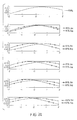
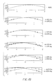
- FIGS. 3A-3C MTF performance plots are measured at best focus using weighted wavelengths (440 nanometers at 15%, 546.1 nanometers at 50%, and 650 nanometers at 35%) at a frequency of 4.45 cycles per millimeter with full field (100%) being 20.58 mm.
- FIG. 3A shows MTF plots for Examples 1 and 2 in wide angle format.
- FIG. 3B shows MTF plots for Example 1 in telephoto (telephoto 1) format.
- FIG. 3C shows MTF plots for Example 2 in an alternative telephoto (telephoto 2) format.
- MTF plots are centered along the diagonal of the film cylinder (long dimension of 24x36mm image format is measured along cylinder radius of curvature in all examples).
- FIGS. 4A-4C describe additional performance characteristics of the variable focal length lens 20 of Examples 1 and 2.
- FIG. 4A shows lateral color correction for Examples 1 and 2 in wide angle format.
- FIG. 4B shows lateral color correction for Example 1 in telephoto (telephoto 1) format.
- FIG. 4C shows lateral color correction for Example 1 in the alternative telephoto (telephoto 2) format.
- FIG. 5A shows two position variable focal length lens 20 in a wide angle format or position while FIG. 5B show two position variable focal length lens 20 in a telephoto format or position.
- Common lens element 26 is a meniscus glass lens and includes spherical surfaces S 1 and S 2 with surface S 1 being convex toward the object plane 40.
- Wide angle lens element 28 is plastic (for example, acrylic or PMMA, etc.) and includes surfaces S 3 and S 4 which are both aspheric.
- Telephoto lens element 32 is plastic (for example, acrylic or PMMA, etc.) and includes surfaces S 5 and S 6 which are both aspheric.
- the first lens element 26 has a focal length of 40.000 mm, and the second lens element 28 has a focal length of 70.131 mm.
- the first lens element 26 has a focal length of 40.000 mm
- the second lens element 32 has a focal length of -304.786 mm.
- FIGS. 6A-6B MTF performance plots are measured at best focus using weighted wavelengths (440 nanometers at 15%, 546.1 nanometers at 50%, and 650 nanometers at 35%) at a frequency of 4.45 cycles per millimeter with full field (100%) being 20.58 mm.
- FIG. 6A shows MTF plots for Example 3 in wide angle format.
- FIG. 6B shows MTF plots for Example 3 in telephoto format. MTF plots are centered along the diagonal of the film cylinder (long dimension of 24x36mm image format is measured along cylinder radius of curvature in all examples).
- FIGS. 8A-8B describe additional performance characteristics of the variable focal length lens 20 of Example 3.
- FIG. 8A shows lateral color correction for Example 3 in wide angle format.
- FIG. 8B shows lateral color correction for Example 3 in telephoto format.
- Common lens element 26 is a meniscus glass lens and includes spherical surfaces S 1 and S 2 with surface S 1 being convex toward the object plane 40.
- Wide angle lens element 28 is plastic (for example, acrylic plastic or PMMA, etc.) and includes surfaces S 3 and S 4 which are both aspheric.
- Telephoto lens element 32 is plastic (styrene) and includes surfaces S 5 and S 6 which are both aspheric.
- the first lens element 26 has a focal length of 40.000 mm
- the second lens element 28 has a focal length of 72.521 mm.
- the first lens element 26 has a focal length of 40.000 mm
- the second lens element 32 has a focal length of-283.278 mm.
- FIGS. 7A-7B MTF performance plots are measured at best focus using weighted wavelengths (440 nanometers at 15%, 546.1 nanometers at 50%, and 650 nanometers at 35%) at a frequency of 4.45 cycles per millimeter with full field (100%) being 20.58 mm.
- FIG. 7A shows MTF plots for Example 4 in wide angle format.
- FIG. 7B shows MTF plots for Example 4 in telephoto format. MTF plots are centered along the diagonal of the film cylinder (long dimension of 24x36mm image format is measured along cylinder radius of curvature in all examples).
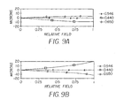
- FIGS. 9A-9B describe additional performance characteristics of the variable focal length lens 20 of Example 4.
- FIG. 9A shows lateral color correction for Example 4 in wide angle format.
- FIG. 9B shows lateral color correction for Example 4 in telephoto format.
- FIG. 10A shows two position variable focal length lens 20 in a wide angle format or position while FIG. 10B shows two position variable focal length lens 20 in a telephoto format or position.
- Common lens element 26 is glass, biconvex, and includes spherical surfaces S 1 and S 2 .
- Wide angle lens element 28 is plastic (for example, acrylic plastic or PMMA, etc.) and includes surfaces S 3 and S 4 which are both aspheric.
- Telephoto lens element 32 is plastic (for example, acrylic plastic or PMMA, etc.) and includes surfaces S 5 and S 6 which are both aspheric.
- the first lens element 26 has a focal length of 40.000 mm, and the second lens element 28 has a focal length of 66.395 mm.
- the first lens element 26 has a focal length of 40.000 mm
- the second lens element 32 has a focal length of -946.925 mm.
- FIGS. 11A-11B MTF performance plots are measured at best focus using weighted wavelengths (440 nanometers at 15%, 546.1 nanometers at 50%, and 650 nanometers at 35%) at a frequency of 4.45 cycles per millimeter with full field (100%) being 20.58 mm.
- FIG. 11A shows MTF plots for Example 5 in wide angle format.
- FIG. 11B shows MTF plots for Example 5 in telephoto format. MTF plots are centered along the diagonal of the film cylinder (long dimension of 24x36mm image format is measured along cylinder radius of curvature in all examples).
- FIGS. 13A-13B describe additional performance characteristics of the variable focal length lens 20 of Example 5.
- FIG. 13A shows lateral color correction for Example 5 in wide angle format.
- FIG. 13B shows lateral color correction for Example 5 in telephoto format.
- Common lens element 26 is glass, biconvex, and includes spherical surfaces S 1 and S 2 .
- Wide angle lens element 28 is plastic (for example, acrylic plastic or PMMA, etc.) and includes surfaces S 3 and S 4 which are both aspheric.
- Telephoto lens element 32 is plastic (styrene) and includes surfaces S 5 and S 6 which are both aspheric.
- the first lens element 26 has a focal length of 40.000 mm, and the second lens element 28 has a focal length of 65.496 mm.
- the first lens element 26 has a focal length of 40.000 mm
- the second lens element 32 has a focal length of-1060.655 mm.
- FIGS. 12A-12B MTF performance plots are measured at best focus using weighted wavelengths (440 nanometers at 15%, 546.1 nanometers at 50%, and 650 nanometers at 35%) at a frequency of 4.45 cycles per millimeter with full field (100%) being 20.58 mm.
- FIG. 12A shows MTF plots for Example 6 in wide angle format.
- FIG. 12B shows MTF plots for Example 6 in telephoto format. MTF plots are centered along the diagonal of the film cylinder (long dimension of 24x36mm image format is measured along cylinder radius of curvature in all examples).
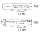
- FIGS. 14A-14B describe additional performance characteristics of the variable focal length lens 20 of Example 6.
- FIG. 14A shows lateral color correction for Example 6 in wide angle format.
- FIG. 14B shows lateral color correction for Example 6 in telephoto format.
- the common lens element 26 of the two position variable focal length lens 20 has an image side surface S 2 that preferably satisfies the condition (1/-20.8) ⁇ c ⁇ (1/5), where c is the curvature of the image side surface. More preferably, the common lens element 26 satisfies the condition (1/-76) ⁇ c ⁇ (1/18.7), where c is the curvature of the image side surface S 2 .
Landscapes
- Physics & Mathematics (AREA)
- General Physics & Mathematics (AREA)
- Optics & Photonics (AREA)
- Lenses (AREA)
Abstract
A two position variable focal length lens is provided. The variable
focal length lens includes a common lens element moveably positioned on an
optical axis; a wide angle lens element moveable between a first location removed
from the optical axis and a first position on the optical axis on an image side of the
common lens element; and a telephoto lens element moveable between a second
location removed from the optical axis and a second position on the optical axis
on the image side of the common lens element. A magnification ratio change is
effected by moving the common lens element along the optical axis and switching
between the wide angle lens element located at the first position on the optical axis
and the telephoto lens element located at the second position on the optical axis.
Description
- This invention relates generally to lens design, and in particular to a variable focal length lens for use in a camera.
- Zoom lens system in which the rear or image side lens units switch out of and into an optical path are known. For example, US Patent No. 4,871,238, which issued to Sato et al., on October 3, 1989, discloses a photographic optical device including a master lens unit having a positive refractive power; a first auxiliary lens unit having a positive refractive power capable of being placed on and off the optical path; and a second auxiliary lens unit having a negative refractive power capable of being placed on and off the optical path. The first auxiliary lens unit is attached to an image-plane side of the master lens unit to form a photographic unit giving a low ratio of magnification. The second auxiliary lens unit is attached to an image-plane side of the master lens unit to form another photographic unit giving a high ratio of magnification. The first and second auxiliary lens units are placed outside of the optical path to form another photographic unit giving a middle ratio of magnification. The zoom lens system disclosed in US Patent No. 4,871,238 is disadvantaged in that each lens unit requires many individual lens components which increases manufacturing costs associated with building the zoom lens system and increases the complexity of the design of the zoom lens system. Additionally, the zoom lens system disclosed in US Patent No. 4,871,238 includes a wide angle, mid- range, and telephoto format (lens position) which increases the cost and complexity associated with the lens driving mechanism.
- Lens systems having a reduced number of individual lens components are also known. For example, US Patent No. 5,677,798, which issued to Hirano et al., on October 14, 1997, discloses an image forming lens system including a positive front lens group, a diaphragm, and a rear lens group, in order from an object to be imaged. The front lens group is made of optical glass. The rear lens group is made of a single meniscus plastic lens having opposed aspheric lens surfaces with a concave surface adjacent to the diaphragm. Additionally, US Patent No. 5,067,803, which issued to Ohno, on November 26, 1991, discloses a photographic wide angle lens which is composed of, from an object side thereof, a first lens of positive meniscus having a convex surface on the object side, and a second lens of positive meniscus having a concave surface on the object side. The wide angle lens has an aspheric surface at least on one of the four lens surfaces provided by the first and second lenses. While the lens systems disclosed in US Patent Nos. 5,677,798 and 5,067,803 have a reduced number of individual lens elements, each lens system is disadvantaged in that the ratio of magnification of the lens system can not be changed.
- Recent surveys of picture taking consumers using a zoom lens indicated that over 90% of all photographs are shot in either a wide angle format or a telephoto format. As such, there is a need for a variable focal length lens system having a reduced number of individual lens components capable of switching between a wide angle format and a telephoto format.
- According to one feature of the present invention, a two position variable focal length lens includes a common lens element moveably positioned on an optical axis. A wide angle lens element is moveable between a first location removed from the optical axis and a first position on the optical axis on an image side of the common lens element. A telephoto lens element is moveable between a second location removed from the optical axis and a second position on the optical axis on the image side of the common lens element. A magnification ratio change is effected by moving the common lens element along the optical axis and switching between the wide angle lens element located at the first position on the optical axis and the telephoto lens element located at the second position on the optical axis. The two position variable focal length lens satisfies the following condition: | fc - fzt |< |fc - fzw|, where fc is a focal length of the common lens element, fzt is a focal length of the two position variable focal length lens in a telephoto position, and fzw is a focal length of the two position variable focal length lens in a wide angle position.
- According to another feature of the present invention, a two position variable focal length lens includes a common lens element moveably positioned on an optical axis. The common lens element has an image side surface with the image side surface having a curvature. The common lens element satisfies the following condition: (1/-20.8 ≤ c ≤ (1/5), where c is the curvature of the image side surface. A wide angle lens element is moveable between a first location removed from the optical axis and a first position on the optical axis on an image side of the common lens element. A telephoto lens element is moveable between a second location removed from the optical axis and a second position on the optical axis on the image side of the common lens element. A magnification ratio change is effected by moving the common lens element along the optical axis and switching between the wide angle lens element located at the first position on the optical axis and the telephoto lens element located at the second position on the optical axis.
- According to another feature of the present invention, a two position variable focal length lens includes a common lens element moveably positioned on an optical axis. A wide angle lens element is moveable between a first location removed from the optical axis and a first position on the optical axis on an image side of the common lens element. A first aperture stop is moveably positioned with the wide angle lens element on an object side of the wide angle lens element. A telephoto lens element is moveable between a second location removed from the optical axis and a second position on the optical axis on the image side of the common lens element. A second aperture stop is moveably positioned with the telephoto lens element on an object side of the telephoto lens element. A magnification ratio change is effected by moving the common lens element along the optical axis and switching between the first aperture stop and the wide angle lens element located at the first position on the optical axis and the second aperture stop and the telephoto lens element located at the second position on the optical axis such that a distance between the common lens element and the first aperture stop is equivalent to a distance between the common lens element and the second aperture stop.
- According to another feature of the present invention, a two position variable focal length lens includes a common lens element moveably positioned on an optical axis. A wide angle lens element having aspheric surfaces is moveable between a first location removed from the optical axis and a first position on the optical axis on an image side of the common lens element. A telephoto lens element having aspheric surfaces is moveable between a second location removed from the optical axis and a second position on the optical axis on the image side of the common lens element. A magnification ratio change is effected by moving the common lens element along the optical axis and switching between the wide angle lens element located at the first position on the optical axis and the telephoto lens element located at the second position on the optical axis. The aspheric surfaces of the telephoto lens element have base radii that are larger than corresponding base radii of the aspheric surfaces of the wide angle lens element.
- According to another feature of the present invention, a two position variable focal length lens includes a common lens element moveably positioned on an optical axis. A wide angle lens element is moveable between a first location removed from the optical axis and a first position on the optical axis on an image side of the common lens element. A telephoto lens element is moveable between a second location removed from the optical axis and a second position on the optical axis on the image side of the common lens element, wherein a magnification ratio change is effected by moving the common lens element along the optical axis and switching between the wide angle lens element located at the first position on the optical axis and the telephoto lens element located at the second position on the optical axis. The two position variable focal length lens satisfies the following condition: fC > ((fZW + fZT) / 2), where fC is a focal length of the common lens element, fZW is a focal length of the two position variable focal length lens in a wide angle position, and fZT is a focal length of the two position variable focal length lens in a telephoto position.
- According to another feature of the present invention, a method of changing a magnification ratio from a wide angle position to telephoto angle position includes providing a common lens element positioned at a first location on an optical axis; providing a wide angle lens element located at a first position on the optical axis on an image side of the common lens element; providing a telephoto lens element located at a location removed from the optical axis; moving the common lens element toward an object plane; moving the telephoto lens element to a second position on the optical axis on the image side of the common lens element; and removing the wide angle lens from the optical axis.
- In the detailed description of the embodiments of the invention presented below, reference is made to the accompanying drawings, in which:
- FIGS. 1A and 1B are schematic cross sectional views of an embodiment made in accordance with the present invention in a wide angle zoom position and telephoto zoom position;
- FIGS. 2A and 2B are cross sectional views of first and second numerical examples made in accordance with the present invention in a wide angle zoom position and a telephoto zoom position;
- FIGS. 3A-3C are MTF performance plots of the first and second examples shown in FIGS. 2A and 2B;
- FIGS. 4A-4C are lateral color aberration curves for the first and second examples shown in FIGS. 2A and 2B;
- FIGS. 5A and 5B are cross sectional views of third and fourth numerical examples made in accordance with the present invention in a wide angle zoom position and a telephoto zoom position;
- FIGS. 6A-7B are MTF performance plots of the third and fourth examples, respectively, shown in FIGS. 5A and 5B;
- FIGS. 8A-9B are lateral color aberration curves for the third and fourth examples, respectively, shown in FIGS. 5A and 5B;
- FIGS. 10A and 10B are cross sectional views of fifth and sixth numerical examples made in accordance with the present invention in a wide angle zoom position and a telephoto zoom position;
- FIGS. 11A-12B are MTF performance plots of the third and fourth examples, respectively, shown in FIGS. 10A and 10B; and
- FIGS. 13A-14B are lateral color aberration curves for the third and fourth examples, respectively, shown in FIGS. 10A and 10B.
-
- The present description will be directed in particular to elements forming part of, or cooperating more directly with, apparatus in accordance with the present invention. It is to be understood that elements not specifically shown or described may take various forms well known to those skilled in the art.
- Referring to FIGS. 1A and 1B, a two position variable
focal length lens 20 is shown. The two position variablefocal length lens 20 includes afirst lens unit 22 and asecond lens unit 24, as viewed from an object side of the two position variablefocal length lens 20. As shown in FIG. 1A, thefirst lens unit 22 includes acommon lens element 26 while thesecond lens unit 24 includes a wideangle lens element 28. Anaperture stop 30 is positioned betweencommon lens element 26 and wideangle lens element 28. As shown in FIG. 1B, thefirst lens unit 22 includes thecommon lens element 26 while thesecond lens unit 24 includes atelephoto lens element 32. Asecond aperture stop 34 is positioned between thecommon lens element 26 and thetelephoto lens element 32.Image plane 36 is cylindrically curved. - Zooming in and zooming out are accomplished by moving the
common lens element 26 along aoptical axis 38 while switching between wideangle lens element 28 andtelephoto lens element 32. For example, as shown in FIG. 1A, two position variablefocal length lens 20 is in a wide angle position. As such, two position variablefocal length lens 20 includesaperture stop 30 positioned betweencommon lens element 26 and wideangle lens element 28. When a telephoto position is desired,common lens element 26 moves towardobject plane 40 in a direction as indicated byarrow 42 whilewide angle lens 28 moves out of theoptical axis 38 in a direction as indicated byarrow 44. As this is occurring, telephoto lens element 32 (shown in phantom in FIG. 1A) moves intooptical axis 38 in a direction as indicated byarrow 46 aftercommon lens element 26 is located on the object side oftelephoto lens element 32. This completes the zoom in process which results in the two position variablefocal length lens 20 being in a telephoto position, as shown in FIG. 1B. - When a wide angle position is desired, the
telephoto lens element 32 moves out of theoptical axis 38 in a direction as indicated byarrow 48 whilecommon lens element 26 moves towardimage plane 36 in a direction as indicated byarrow 50. Wideangle lens element 28 moves intooptical axis 38 in a direction as indicated byarrow 52 such thatcommon lens element 26 is on the object side of wideangle lens element 32. This completes the zoom out process which results in the two position variablefocal length lens 20 being in the wide angle position as shown in FIG. 1A. - While the motion of the wide
angle lens element 28 and thetelephoto lens element 32 is generally perpendicular to theoptical axis 38, other motion angles can be incorporated with substantially similar results. The motion ofcommon lens element 26 is generally parallel tooptical axis 38. Additionally,aperture stop 30 moves into and out ofoptical axis 38 with wideangle lens element 28 whilesecond aperture stop 34 moves into and out ofoptical axis 38 withtelephoto lens element 32. Finally,common lens element 26 does not stop at a mid-range position. The movement of two position variablefocal length lens 20 is from a wide angle position directly to a telephoto position or directly from a telephoto position to a wide angle position. - Referring to FIGS. 2A and 2B, a first example of the two position variable
focal length lens 20 is shown. FIG. 2A shows two position variablefocal length lens 20 in a wide angle format or position while FIG. 2B show two position variablefocal length lens 20 in a telephoto format or position.Common lens element 26 is glass and includes surface S1 which is spherical and convex toward theobject plane 40 while surface S2 is plano. Wideangle lens element 28 is plastic (for example, acrylic plastic or PMMA, etc.) and includes surfaces S3 and S4 which are both aspheric.Telephoto lens element 32 is plastic (styrene) and includes surfaces S5A and S6A which are both aspheric. - A second example is also shown in FIGS. 2A and 2B. In this example,
common lens element 26 is glass and includes surface S1 which is spherical and convex toward theobject plane 40 while surface S2 is plano. Wideangle lens element 28 is plastic (for example, acrylic plastic or PMMA, etc.) and includes surfaces S3 and S4 which are both aspheric.Telephoto lens element 32 is plastic (for example, acrylic or PMMA, etc.) and includes surfaces S5B and S6B which are both aspheric. -
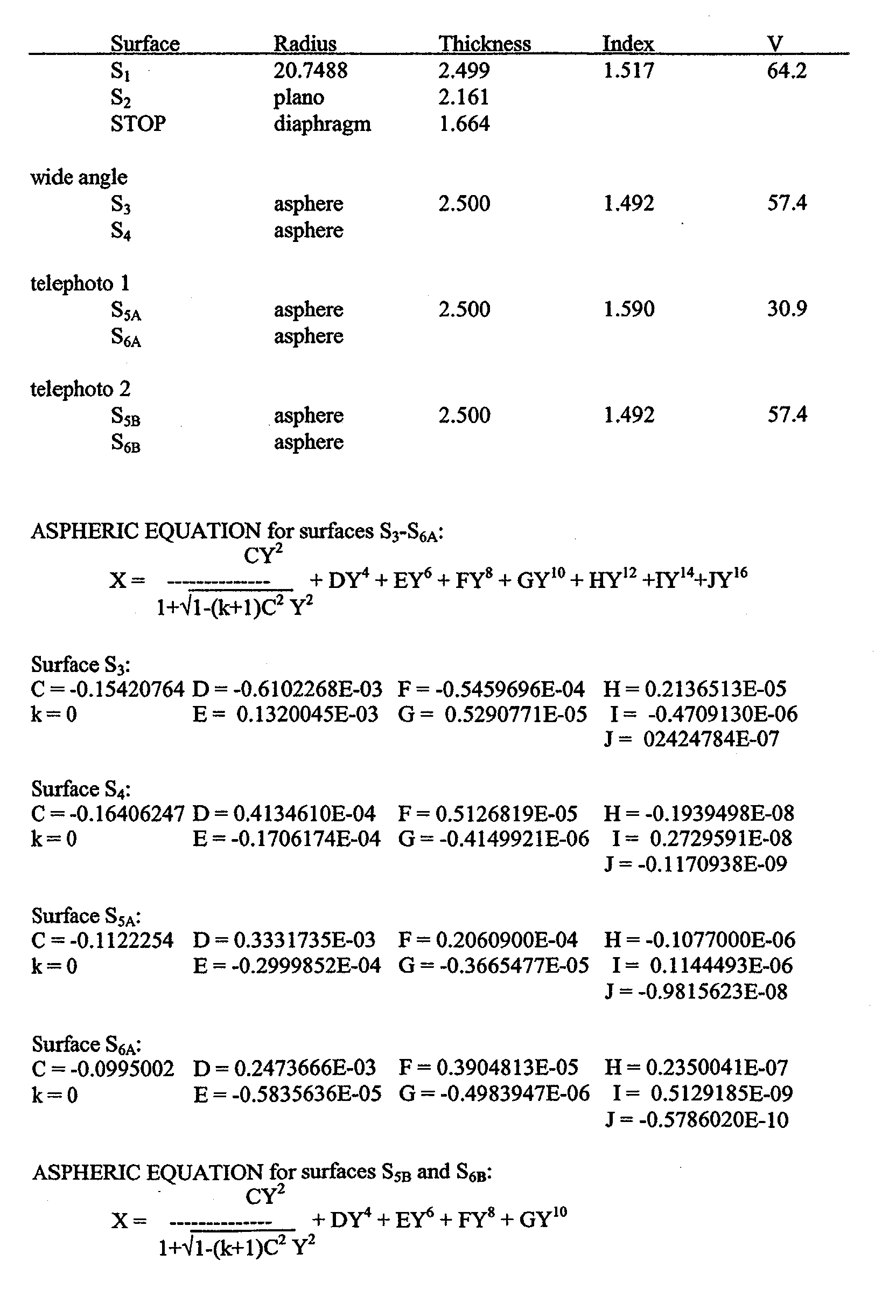
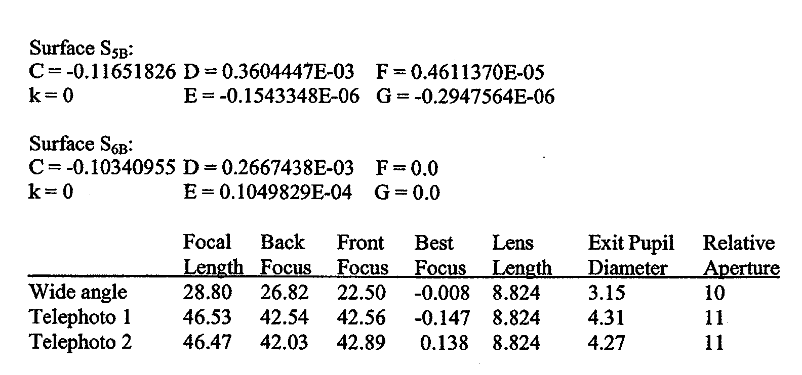
- In wide angle format, Examples 1 and 2 have a cylindrically curved image plane with a radius = -120.0; a semi-field of 36.45°; and a semi-diagonal of 21.63 (Illum.), 20.58 (Image). The
first lens element 26 has a focal length of 40.000 mm, and thesecond lens element 28 has a focal length of 65.834 mm. - In
telephoto 1 format, Example 1 has a cylindrically curved image plane with a radius = -120.0; a semi-field of 24.66°; and a semi-diagonal of 21.63 (Illum.), 20.58 (Image). Thefirst lens element 26 has a focal length of 40.000 mm, and thesecond lens element 32 has a focal length of -727.007 mm. - In
telephoto 2 format, Example 2 has a cylindrically curved image plane with a radius = -120.0; a semi-field of 24.64°; and a semi-diagonal of 21.63 (Illum.), 20.58 (Image). Thefirst lens element 26 has a focal length of 40.000, and thesecond lens element 32 has a focal length of -642.625. - Referring to FIGS. 3A-3C, MTF performance plots are measured at best focus using weighted wavelengths (440 nanometers at 15%, 546.1 nanometers at 50%, and 650 nanometers at 35%) at a frequency of 4.45 cycles per millimeter with full field (100%) being 20.58 mm. FIG. 3A shows MTF plots for Examples 1 and 2 in wide angle format. FIG. 3B shows MTF plots for Example 1 in telephoto (telephoto 1) format. FIG. 3C shows MTF plots for Example 2 in an alternative telephoto (telephoto 2) format. MTF plots are centered along the diagonal of the film cylinder (long dimension of 24x36mm image format is measured along cylinder radius of curvature in all examples).
- FIGS. 4A-4C describe additional performance characteristics of the variable
focal length lens 20 of Examples 1 and 2. FIG. 4A shows lateral color correction for Examples 1 and 2 in wide angle format. FIG. 4B shows lateral color correction for Example 1 in telephoto (telephoto 1) format. FIG. 4C shows lateral color correction for Example 1 in the alternative telephoto (telephoto 2) format. - Referring to FIGS. 5A and 5B, a third example of the two position variable
focal length lens 20 is shown. FIG. 5A shows two position variablefocal length lens 20 in a wide angle format or position while FIG. 5B show two position variablefocal length lens 20 in a telephoto format or position.Common lens element 26 is a meniscus glass lens and includes spherical surfaces S1 and S2 with surface S1 being convex toward theobject plane 40. Wideangle lens element 28 is plastic (for example, acrylic or PMMA, etc.) and includes surfaces S3 and S4 which are both aspheric.Telephoto lens element 32 is plastic (for example, acrylic or PMMA, etc.) and includes surfaces S5 and S6 which are both aspheric. -


- In wide angle, Example 3 has a cylindrically curved image plane with a radius = -120.0; a semi-field of 36.55°; and a semi-diagonal of 21.63 (Illum.), 20.58 (Image). The
first lens element 26 has a focal length of 40.000 mm, and thesecond lens element 28 has a focal length of 70.131 mm. - In telephoto, Example 3 has a cylindrically curved image plane with a radius = -120.0; a semi-field of 24.38°; and a semi-diagonal of 21.63 (Illum.), 20.58 (Image). The
first lens element 26 has a focal length of 40.000 mm, and thesecond lens element 32 has a focal length of -304.786 mm. - Referring to FIGS. 6A-6B, MTF performance plots are measured at best focus using weighted wavelengths (440 nanometers at 15%, 546.1 nanometers at 50%, and 650 nanometers at 35%) at a frequency of 4.45 cycles per millimeter with full field (100%) being 20.58 mm. FIG. 6A shows MTF plots for Example 3 in wide angle format. FIG. 6B shows MTF plots for Example 3 in telephoto format. MTF plots are centered along the diagonal of the film cylinder (long dimension of 24x36mm image format is measured along cylinder radius of curvature in all examples).
- FIGS. 8A-8B describe additional performance characteristics of the variable
focal length lens 20 of Example 3. FIG. 8A shows lateral color correction for Example 3 in wide angle format. FIG. 8B shows lateral color correction for Example 3 in telephoto format. - Again referring to FIGS. 5A and 5B, a fourth example is shown.
Common lens element 26 is a meniscus glass lens and includes spherical surfaces S1 and S2 with surface S1 being convex toward theobject plane 40. Wideangle lens element 28 is plastic (for example, acrylic plastic or PMMA, etc.) and includes surfaces S3 and S4 which are both aspheric.Telephoto lens element 32 is plastic (styrene) and includes surfaces S5 and S6 which are both aspheric. -

- In wide angle, Example 4 has a cylindrically curved image plane with a radius = -120.0; a semi-field of 36.52°; and a semi-diagonal of 21.63 (Illum.), 20.58 (Image). The
first lens element 26 has a focal length of 40.000 mm, and thesecond lens element 28 has a focal length of 72.521 mm. - In telephoto, Example 4 has a cylindrically curved image plane with a radius = -120.0; a semi-field of 24.35°; and a semi-diagonal of 21.63 (Illum.), 20.58 (Image). The
first lens element 26 has a focal length of 40.000 mm, and thesecond lens element 32 has a focal length of-283.278 mm. - Referring to FIGS. 7A-7B, MTF performance plots are measured at best focus using weighted wavelengths (440 nanometers at 15%, 546.1 nanometers at 50%, and 650 nanometers at 35%) at a frequency of 4.45 cycles per millimeter with full field (100%) being 20.58 mm. FIG. 7A shows MTF plots for Example 4 in wide angle format. FIG. 7B shows MTF plots for Example 4 in telephoto format. MTF plots are centered along the diagonal of the film cylinder (long dimension of 24x36mm image format is measured along cylinder radius of curvature in all examples).
- FIGS. 9A-9B describe additional performance characteristics of the variable
focal length lens 20 of Example 4. FIG. 9A shows lateral color correction for Example 4 in wide angle format. FIG. 9B shows lateral color correction for Example 4 in telephoto format. - Referring to FIGS. 10A and 10B, a fifth example of the two position variable
focal length lens 20 is shown. FIG. 10A shows two position variablefocal length lens 20 in a wide angle format or position while FIG. 10B shows two position variablefocal length lens 20 in a telephoto format or position.Common lens element 26 is glass, biconvex, and includes spherical surfaces S1 and S2. Wideangle lens element 28 is plastic (for example, acrylic plastic or PMMA, etc.) and includes surfaces S3 and S4 which are both aspheric.Telephoto lens element 32 is plastic (for example, acrylic plastic or PMMA, etc.) and includes surfaces S5 and S6 which are both aspheric. -
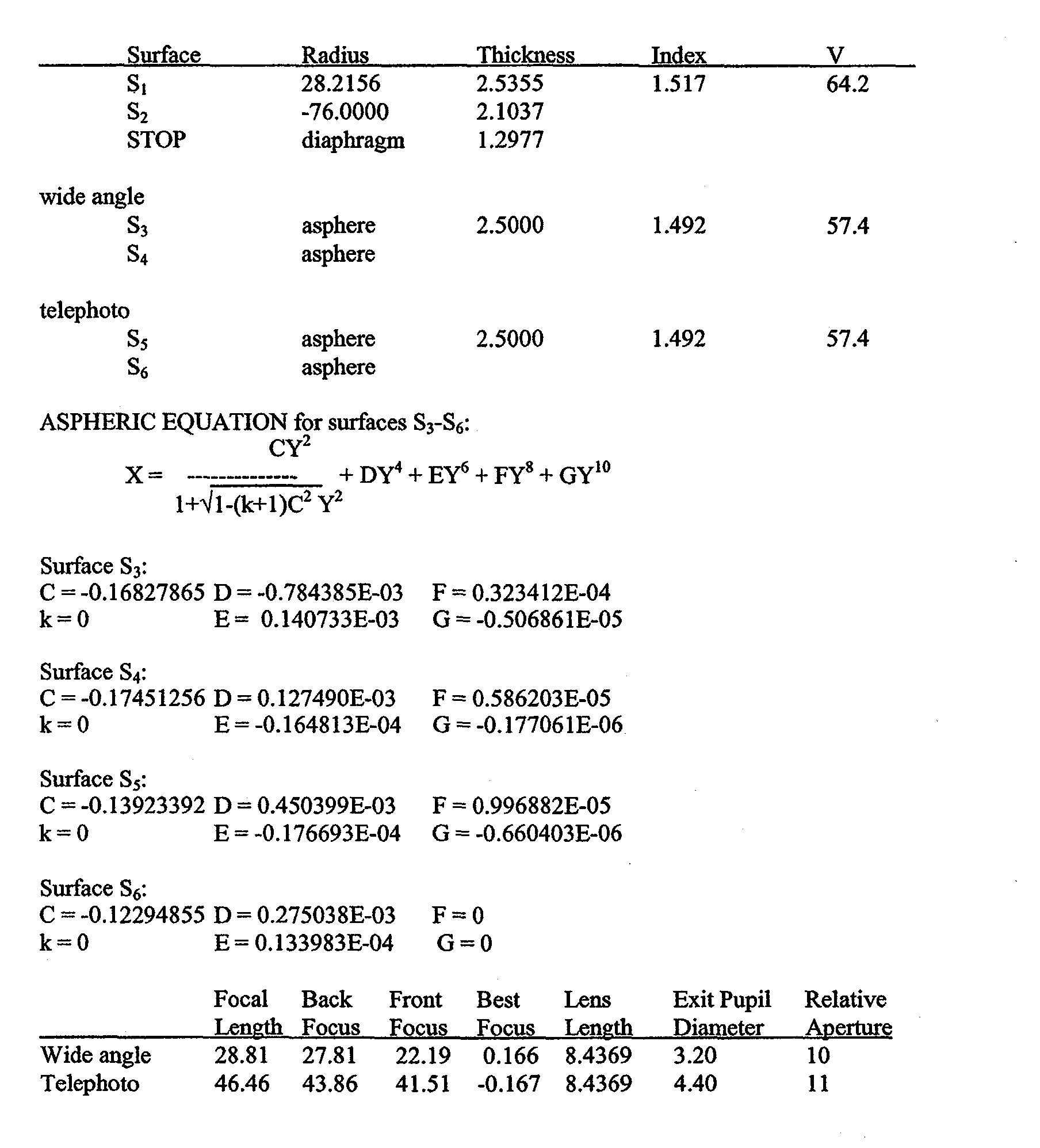
- In wide angle, Example 5 has a cylindrically curved image plane with a radius = -120.0; a semi-field of 36.51°; and a semi-diagonal of 21.63 (Illum.), 20.58 (Image). The
first lens element 26 has a focal length of 40.000 mm, and thesecond lens element 28 has a focal length of 66.395 mm. - In telephoto, Example 5 has a cylindrically curved image plane with a radius = -120.0; a semi-field of 24.83°; and a semi-diagonal of 21.63 (Illum.), 20.58 (Image). The
first lens element 26 has a focal length of 40.000 mm, and thesecond lens element 32 has a focal length of -946.925 mm. - Referring to FIGS. 11A-11B, MTF performance plots are measured at best focus using weighted wavelengths (440 nanometers at 15%, 546.1 nanometers at 50%, and 650 nanometers at 35%) at a frequency of 4.45 cycles per millimeter with full field (100%) being 20.58 mm. FIG. 11A shows MTF plots for Example 5 in wide angle format. FIG. 11B shows MTF plots for Example 5 in telephoto format. MTF plots are centered along the diagonal of the film cylinder (long dimension of 24x36mm image format is measured along cylinder radius of curvature in all examples).
- FIGS. 13A-13B describe additional performance characteristics of the variable
focal length lens 20 of Example 5. FIG. 13A shows lateral color correction for Example 5 in wide angle format. FIG. 13B shows lateral color correction for Example 5 in telephoto format. - Again referring to FIGS. 10A and 10B, a sixth example is shown.
Common lens element 26 is glass, biconvex, and includes spherical surfaces S1 and S2. Wideangle lens element 28 is plastic (for example, acrylic plastic or PMMA, etc.) and includes surfaces S3 and S4 which are both aspheric.Telephoto lens element 32 is plastic (styrene) and includes surfaces S5 and S6 which are both aspheric. -


- In wide angle, Example 6 has a cylindrically curved image plane with a radius = -120.0; a semi-field of 35.87°; and a semi-diagonal of 21.63 (Illum.), 20.58 (Image). The
first lens element 26 has a focal length of 40.000 mm, and thesecond lens element 28 has a focal length of 65.496 mm. - In telephoto, Example 6 has a cylindrically curved image plane with a radius = -120.0; a semi-field of 24.70°; and a semi-diagonal of 21.63 (Illum.), 20.58 (Image). The
first lens element 26 has a focal length of 40.000 mm, and thesecond lens element 32 has a focal length of-1060.655 mm. - Referring to FIGS. 12A-12B, MTF performance plots are measured at best focus using weighted wavelengths (440 nanometers at 15%, 546.1 nanometers at 50%, and 650 nanometers at 35%) at a frequency of 4.45 cycles per millimeter with full field (100%) being 20.58 mm. FIG. 12A shows MTF plots for Example 6 in wide angle format. FIG. 12B shows MTF plots for Example 6 in telephoto format. MTF plots are centered along the diagonal of the film cylinder (long dimension of 24x36mm image format is measured along cylinder radius of curvature in all examples).
- FIGS. 14A-14B describe additional performance characteristics of the variable
focal length lens 20 of Example 6. FIG. 14A shows lateral color correction for Example 6 in wide angle format. FIG. 14B shows lateral color correction for Example 6 in telephoto format. - The
common lens element 26 of the two position variablefocal length lens 20 has an image side surface S2 that preferably satisfies the condition (1/-20.8) ≤ c ≤ (1/5), where c is the curvature of the image side surface. More preferably, thecommon lens element 26 satisfies the condition (1/-76) ≤ c ≤ (1/18.7), where c is the curvature of the image side surface S2. Still more preferably, thecommon lens element 26 satisfies the condition: (1/100) ≤ c < (1/25.5), where c is the curvature of the image side surface S2, and more preferably, thecommon lens element 26 satisfies the condition: c = 0, where c is the curvature of the image side surface S2 of thecommon lens element 26. - The invention has been described in detail with particular reference to certain preferred embodiments thereof, but it will be understood that variations and modifications can be effected within the scope of the invention.
Claims (10)
- A two position variable focal length lens comprising:a common lens element (26) moveably positioned on an optical axis;a wide angle lens element (28) moveable between a first location removed from the optical axis and a first position on the optical axis on an image side of the common lens element; anda telephoto lens element (32) moveable between a second location removed from the optical axis and a second position on the optical axis on the image side of the common lens element, wherein a magnification ratio change is effected by moving the common lens element along the optical axis and switching between the wide angle lens element located at the first position on the optical axis and the telephoto lens element located at the second position on the optical axis and the two position variable focal length lens satisfies the following condition: |fc - fzt | < | fc - fzw |, where fc is a focal length of the common lens element, fzt is a focal length of the two position variable focal length lens in a telephoto position, and fzw is a focal length of the two position variable focal length lens in a wide angle position.
- The two position variable focal length lens of Claim 1, wherein the variable focal length lens satisfies the following condition: fc / fzt> 0.85.
- The two position variable focal length lens of Claim 1, wherein both the wide angle lens element and the telephoto lens element are made from plastic, and the common lens element is a glass element.
- The two position variable focal length lens of Claim 1, wherein the common lens element has an image side surface and satisfies the following condition: -(1/76)≤c≤(1/18.7), where c is the curvature of the image side surface of the common lens element.
- The two position variable focal length lens of Claim 1, wherein the common lens element satisfies the following condition: c = 0, where c is the curvature of the image side surface of the common lens element.
- The two position variable focal length lens of Claim 1, wherein the wide angle lens element is meniscus having a convex surface on the image side of the wide angle lens element and the telephoto lens element is meniscus having a convex surface on the image side of the telephoto lens element.
- A method of changing a magnification ratio from a wide angle position to telephoto angle position comprising:providing a common lens element positioned at a first location on an optical axis;providing a wide angle lens element located at a first position on the optical axis on an image side of the common lens element;providing a telephoto lens element located at a location removed from the optical axis;moving the common lens element toward an object plane;moving the telephoto lens element to a second position on the optical axis on the image side of the common lens element; andremoving the wide angle lens from the optical axis.
- The method of Claim 7, wherein moving the telephoto lens element to a second position on the optical axis on the image side of the common lens element and removing the wide angle lens from the optical path occurs simultaneously.
- The method of Claim 7 further comprising:providing a first aperture stop positioned on an object side of the wide angle lens element, the first aperture stop being spaced apart from the common lens element by a predetermined distance; andremoving the first aperture stop from the optical axis with the wide angle lens element.
- The method of Claim 9 further comprising:providing a second aperture stop positioned on an object side of the telephoto lens element; andmoving the second aperture stop to the second position on the optical axis with the telephoto lens element, wherein the second aperture stop is positioned spaced apart from the common lens element at the predetermined distance.
Applications Claiming Priority (2)
| Application Number | Priority Date | Filing Date | Title |
|---|---|---|---|
| US225669 | 1999-01-05 | ||
| US10/225,669 US6873473B2 (en) | 2002-08-22 | 2002-08-22 | Two position variable focal length lens |
Publications (1)
| Publication Number | Publication Date |
|---|---|
| EP1391767A1 true EP1391767A1 (en) | 2004-02-25 |
Family
ID=31187996
Family Applications (1)
| Application Number | Title | Priority Date | Filing Date |
|---|---|---|---|
| EP03077514A Withdrawn EP1391767A1 (en) | 2002-08-22 | 2003-08-11 | Variable focal length lens using switchable lens groups |
Country Status (3)
| Country | Link |
|---|---|
| US (1) | US6873473B2 (en) |
| EP (1) | EP1391767A1 (en) |
| JP (1) | JP2004086215A (en) |
Families Citing this family (4)
| Publication number | Priority date | Publication date | Assignee | Title |
|---|---|---|---|---|
| JP2005334237A (en) * | 2004-05-26 | 2005-12-08 | Olympus Corp | Endoscope apparatus |
| US7158311B1 (en) * | 2005-07-29 | 2007-01-02 | Eastman Kodak Company | Interchangeable lens system |
| JP6529396B2 (en) * | 2015-09-04 | 2019-06-12 | オリンパス株式会社 | Imaging optical system, imaging device and capsule endoscope |
| US10578853B2 (en) | 2015-09-04 | 2020-03-03 | Olympus Corporation | Image forming optical system, image pickup apparatus, optical apparatus, and capsule endoscope |
Citations (5)
| Publication number | Priority date | Publication date | Assignee | Title |
|---|---|---|---|---|
| JPS59193405A (en) * | 1983-04-18 | 1984-11-02 | Fuji Photo Film Co Ltd | Focusing device of wide angle and telephoto switching camera |
| US4871238A (en) * | 1986-03-06 | 1989-10-03 | Canon Kabushiki Kaisha | Photographic optical device with variable magnification |
| US5321548A (en) * | 1991-09-26 | 1994-06-14 | Olympus Optical Co., Ltd. | Real image mode variable magnification finder optical system |
| US5515206A (en) * | 1994-11-15 | 1996-05-07 | Gentle Peng | Multi-facet lens component |
| US6307683B1 (en) * | 1999-03-25 | 2001-10-23 | Fuji Photo Optical Co., Ltd | Zoom lens |
Family Cites Families (8)
| Publication number | Priority date | Publication date | Assignee | Title |
|---|---|---|---|---|
| US3637282A (en) * | 1970-02-21 | 1972-01-25 | Olympus Optical Co | Elongated variable magnification optical system having selectively interchangeable lenses |
| US5000552A (en) * | 1989-02-21 | 1991-03-19 | Eastman Kodak Company | Optical system for use in photographic devices |
| US5067803A (en) * | 1991-03-06 | 1991-11-26 | Fuji Photo Optical Co., Ltd. | Photographic wide angle lens |
| US5327291A (en) * | 1992-03-30 | 1994-07-05 | Polaroid Corporation | Compact objective lens |
| JP3316936B2 (en) * | 1992-10-22 | 2002-08-19 | 株式会社ニコン | Illumination optical device, exposure device, and transfer method using the exposure device |
| US5677798A (en) * | 1993-10-28 | 1997-10-14 | Asahi Kogaku Kogyo Kabushiki Kaisha | Image forming lens system |
| JP3725276B2 (en) * | 1997-01-23 | 2005-12-07 | フジノン株式会社 | Imaging lens |
| US6282377B1 (en) * | 2000-01-11 | 2001-08-28 | Eastman Kodak Company | Dual lens camera |
-
2002
- 2002-08-22 US US10/225,669 patent/US6873473B2/en not_active Expired - Fee Related
-
2003
- 2003-08-11 EP EP03077514A patent/EP1391767A1/en not_active Withdrawn
- 2003-08-22 JP JP2003298851A patent/JP2004086215A/en active Pending
Patent Citations (5)
| Publication number | Priority date | Publication date | Assignee | Title |
|---|---|---|---|---|
| JPS59193405A (en) * | 1983-04-18 | 1984-11-02 | Fuji Photo Film Co Ltd | Focusing device of wide angle and telephoto switching camera |
| US4871238A (en) * | 1986-03-06 | 1989-10-03 | Canon Kabushiki Kaisha | Photographic optical device with variable magnification |
| US5321548A (en) * | 1991-09-26 | 1994-06-14 | Olympus Optical Co., Ltd. | Real image mode variable magnification finder optical system |
| US5515206A (en) * | 1994-11-15 | 1996-05-07 | Gentle Peng | Multi-facet lens component |
| US6307683B1 (en) * | 1999-03-25 | 2001-10-23 | Fuji Photo Optical Co., Ltd | Zoom lens |
Non-Patent Citations (1)
| Title |
|---|
| PATENT ABSTRACTS OF JAPAN vol. 009, no. 058 (P - 341) 14 March 1985 (1985-03-14) * |
Also Published As
| Publication number | Publication date |
|---|---|
| US20040036981A1 (en) | 2004-02-26 |
| JP2004086215A (en) | 2004-03-18 |
| US6873473B2 (en) | 2005-03-29 |
Similar Documents
| Publication | Publication Date | Title |
|---|---|---|
| JP3822268B2 (en) | Zoom lens | |
| JP3478637B2 (en) | Small zoom lens | |
| JP2006337745A5 (en) | ||
| JP3387524B2 (en) | Variable magnification finder optical system | |
| JP3035830B2 (en) | Zoom lens | |
| JPH11305125A (en) | Zoom lens and photographing apparatus using the same | |
| KR100388917B1 (en) | Optic system for photo lens | |
| JPH05303035A (en) | Internal focusing super-telephoto zoom lens | |
| JP2001133687A5 (en) | ||
| JP2003050352A (en) | Zoom lens and optical device using the same | |
| JP2005055625A (en) | Zoom lens, camera device and projector | |
| TW201502571A (en) | Imaging optical system | |
| CN100549750C (en) | Zoom-lens system | |
| JP7055652B2 (en) | Zoom lens and image pickup device | |
| JP2001154093A5 (en) | ||
| JP2005134746A (en) | Zoom lens and imaging apparatus having the same | |
| CN102375222A (en) | Lens apparatus and image pickup apparatus | |
| TWI819551B (en) | Imaging lens system, image capturing unit and electronic device | |
| CN109324400B (en) | A compact 2x high-definition zoom glass-plastic lens and its imaging method | |
| CN218497254U (en) | Zoom lens | |
| JP2003043355A (en) | Two group zoom lens having weak front element | |
| JP2001356268A5 (en) | ||
| JP3713370B2 (en) | Zoom optical system | |
| TW202328735A (en) | Lens assembly and image capture apparatus thereof | |
| US6873473B2 (en) | Two position variable focal length lens |
Legal Events
| Date | Code | Title | Description |
|---|---|---|---|
| PUAI | Public reference made under article 153(3) epc to a published international application that has entered the european phase |
Free format text: ORIGINAL CODE: 0009012 |
|
| AK | Designated contracting states |
Kind code of ref document: A1 Designated state(s): AT BE BG CH CY CZ DE DK EE ES FI FR GB GR HU IE IT LI LU MC NL PT RO SE SI SK TR |
|
| AX | Request for extension of the european patent |
Extension state: AL LT LV MK |
|
| 17P | Request for examination filed |
Effective date: 20040809 |
|
| AKX | Designation fees paid |
Designated state(s): DE FR GB |
|
| 17Q | First examination report despatched |
Effective date: 20041206 |
|
| STAA | Information on the status of an ep patent application or granted ep patent |
Free format text: STATUS: THE APPLICATION IS DEEMED TO BE WITHDRAWN |
|
| 18D | Application deemed to be withdrawn |
Effective date: 20050617 |