EP1391646A2 - Valve - Google Patents
Valve Download PDFInfo
- Publication number
- EP1391646A2 EP1391646A2 EP03018833A EP03018833A EP1391646A2 EP 1391646 A2 EP1391646 A2 EP 1391646A2 EP 03018833 A EP03018833 A EP 03018833A EP 03018833 A EP03018833 A EP 03018833A EP 1391646 A2 EP1391646 A2 EP 1391646A2
- Authority
- EP
- European Patent Office
- Prior art keywords
- valve
- sensor
- valve according
- housing
- calculation means
- Prior art date
- Legal status (The legal status is an assumption and is not a legal conclusion. Google has not performed a legal analysis and makes no representation as to the accuracy of the status listed.)
- Withdrawn
Links
Images


Classifications
-
- F—MECHANICAL ENGINEERING; LIGHTING; HEATING; WEAPONS; BLASTING
- F16—ENGINEERING ELEMENTS AND UNITS; GENERAL MEASURES FOR PRODUCING AND MAINTAINING EFFECTIVE FUNCTIONING OF MACHINES OR INSTALLATIONS; THERMAL INSULATION IN GENERAL
- F16K—VALVES; TAPS; COCKS; ACTUATING-FLOATS; DEVICES FOR VENTING OR AERATING
- F16K27/00—Construction of housing; Use of materials therefor
- F16K27/02—Construction of housing; Use of materials therefor of lift valves
- F16K27/0254—Construction of housing; Use of materials therefor of lift valves with conical shaped valve members
-
- F—MECHANICAL ENGINEERING; LIGHTING; HEATING; WEAPONS; BLASTING
- F16—ENGINEERING ELEMENTS AND UNITS; GENERAL MEASURES FOR PRODUCING AND MAINTAINING EFFECTIVE FUNCTIONING OF MACHINES OR INSTALLATIONS; THERMAL INSULATION IN GENERAL
- F16K—VALVES; TAPS; COCKS; ACTUATING-FLOATS; DEVICES FOR VENTING OR AERATING
- F16K1/00—Lift valves or globe valves, i.e. cut-off apparatus with closure members having at least a component of their opening and closing motion perpendicular to the closing faces
- F16K1/02—Lift valves or globe valves, i.e. cut-off apparatus with closure members having at least a component of their opening and closing motion perpendicular to the closing faces with screw-spindle
- F16K1/06—Special arrangements for improving the flow, e.g. special shape of passages or casings
- F16K1/10—Special arrangements for improving the flow, e.g. special shape of passages or casings in which the spindle is inclined to the general direction of flow
-
- G—PHYSICS
- G01—MEASURING; TESTING
- G01F—MEASURING VOLUME, VOLUME FLOW, MASS FLOW OR LIQUID LEVEL; METERING BY VOLUME
- G01F1/00—Measuring the volume flow or mass flow of fluid or fluent solid material wherein the fluid passes through a meter in a continuous flow
- G01F1/68—Measuring the volume flow or mass flow of fluid or fluent solid material wherein the fluid passes through a meter in a continuous flow by using thermal effects
- G01F1/684—Structural arrangements; Mounting of elements, e.g. in relation to fluid flow
- G01F1/6842—Structural arrangements; Mounting of elements, e.g. in relation to fluid flow with means for influencing the fluid flow
-
- G—PHYSICS
- G01—MEASURING; TESTING
- G01F—MEASURING VOLUME, VOLUME FLOW, MASS FLOW OR LIQUID LEVEL; METERING BY VOLUME
- G01F15/00—Details of, or accessories for, apparatus of groups G01F1/00 - G01F13/00 insofar as such details or appliances are not adapted to particular types of such apparatus
- G01F15/005—Valves
Definitions
- the present invention relates to a valve for liquids Installation in lines, especially a line valve for Water supply facilities.
- the valve has a housing and a valve bonnet.
- the housing has a first nozzle for connection to the line, a second connector for connection to the Line, as well as a third nozzle for receiving the Valve top.
- the valve upper part comprises a valve cone, which with a valve seat in the housing for adjusting the flow cooperates through the valve.
- the valve seat is included fluidically between the first and the second nozzle arranged.
- Such a valve is known from EP 0 946 910 B1 known.
- This publication concerns one Line regulating valve for regulating volume flows in Pipelines, with at least one in a flow housing integrated sensor records the volume flow and with a Evaluation unit and the flow characteristic of each associated housing containing data storage is connected.
- the sensor works according to a calorimetric measuring principle and is permanently and permanently installed in the line regulating valve. disadvantage the permanent installation of the sensors in the line regulating valve, that the sensors, especially for fittings with a smaller one Nominal size are disproportionately expensive compared to the overall valve. On Another disadvantage is that the sensor is not dirty can be cleaned.
- EP 0 592 398 B1 and DE 196 1925 C2 are valves for hot water systems partially known string control systems, which nozzle for the have removable insertion of sensors. These socks are attached in front of and behind a constriction of the valve, so that the sensors with their important elements for the measurement in front of and behind the constriction the flow through the valve are protruding into it.
- the bottleneck can be one act special aperture, such as in DE 196 1925 C2 disclosed, or the narrow point is concerned around the valve seat of the valve as it did from the other two Publications is known.
- the in the three mentioned publications disclosed valves are for measuring the Flow velocity or the flow rate after the Differential pressure measuring principle prepared.
- Pressure sensors can over the nozzles are brought into the flow to the pressure before and behind the bottleneck. From the pressure difference can then according to the differential pressure method the flow velocity or the flow through the valve can be calculated.
- the in the 3rd mentioned documents disclosed valves with sockets for the Measurement of the flow velocity and the flow rate after the differential pressure method come for a measurement of Flow velocity according to the calorimetric measuring principle out of the question. For one thing, it is not possible to use a calorimetric To carry out measurement by means of measuring spigots in front of and behind one Constriction are appropriate. On the other hand, they are from the publication Known sensors EP 0 946 910 B1 are geometrically designed such that they are not in the valves known from the three publications can be used with measuring spigots.
- the measuring nozzle the Valves known from the three publications mentioned, have such a small cross section that one from EP 0 946 910 B1 known sensor not used in these sockets can be.
- the narrow cross-section of the sockets is therefore necessary because the sensors for measuring the Flow velocities according to the differential pressure method can be inserted into the nozzle during operation of the system and off the nozzle should be removable. This makes it necessary To keep the cross section of the nozzle as small as possible so that when use or if possible remove none when removing the sensors Liquid can escape from the line through the nozzle.
- valve with the Features solved according to claim 1.
- the sensors can be used to measure in the valve be used; after the measurement is finished, the However, sensors removed from the valve again, for example for Measurements on another valve are available.
- the valve preferably has two further connecting pieces for connection of the sensors.
- At least one of the further nozzles a ring or a cuff made of an elastomer.
- This ring or this cuff can in the axial direction of the Be pressed together around the ring or the cuff. This closes the ring or cuff, however, when inserting the sensor in the further nozzle of Sensor is pushed through the ring or the cuff, to be able to penetrate into the housing.
- At least one of the further nozzles can have at least one simply insert an axially perforated plug made of an elastomer, the hole of the plug when sensors are not used is closed.
- the sensor is through the perforated plug pushed through it and then ready for measurements in the housing to stand.
- the further connecting pieces can be on the first or second nozzle can be arranged.
- the other nozzles can in the axial direction of the first or second nozzle be arranged one behind the other. It is also possible that the further nozzles in the circumferential direction of the first or second Stubs are arranged side by side.
- Two sensor lances can be inserted into the other nozzles or be used. ln the area of the tip of the sensor lances at least one temperature sensor used. A part of Temperature sensors must be so that the measurements after the calorimetric measuring principle can be performed heated his.
- the temperature sensors can also have a device for Signal amplification can be connected. Likewise, the Temperature sensors directly or with the interposition of Device for signal amplification with a calculation means be connected. In the calculation means, the from the Temperature sensors detected temperatures of the volume flow be calculated. This can also be calculated by calculating the Flow rate in an intermediate step.
- the calculation means are advantageous with a display means connected, on which the measured value of the Volume flow, the flow rate or the Temperatures can be measured.
- the calculation means and the display means the device for signal amplification can be in one be arranged common housing.
- the calculation means can also on the Sensor lance must be attached.
- the means of calculation is then preferably at the opposite end of the Sensor lance attached.
- the calculation means can then be a Include housing which is attached to the sensor lance.
- the Computing means can further comprise electrical components with which the calculation is carried out. The components are preferably on a circuit carrier of the calculation means appropriate. With a valve with such a calculation means, the calculation means is preferably outside the further Nozzle, while the sensor lance is guided through the nozzle itself is.
- a sensor lance can have a diameter of have up to 4 mm, so that the sensor lance through an axial perforated plug can be passed, the hole itself after removing the sensor lance in the relaxed state again closes to prevent leakage of liquid from the valve prevent.
- a sensor according to the invention which is used to carry out Measurements according to the calorimetric measuring principle on a previously mentioned valve is suitable, has a sensor lance that a first end with a tip in which at least two Temperature sensors are used, one of which is heated.
- the Sensor lance also has a second end on which a housing is attached in which electrical components are arranged.
- the sensor has a calculation means, which the housing and includes the electrical component.
- the sensor lance of a sensor according to the invention can have a diameter of up to 4 mm have.
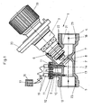
- the valves 1 according to Figures 1 to 6 have a housing 2 and a valve upper part 3.
- the housing comprises a first nozzle 4 and a second nozzle 5. Via this nozzle 4, 5, the valve 1 can be switched into a line. These are on the inside the nozzle 4, 5 thread 23 is provided.
- the housing 2 comprises also a third nozzle 6 for connecting the valve upper part 3.
- the third nozzle 6 also has an internal thread 21 into which the valve upper part 2 with the interposition of seals 22 is screwed in.
- valve spindle In the upper valve part 3 is a valve spindle, not shown arranged, the upper end of which is connected to a handwheel 19. Via the handwheel 19, the valve spindle is within the rest Upper valve part axially displaceable. The position of the valve spindle can via a dial, not shown, which can be operated with the handwheel 19 connected is displayed in a viewing window 20.
- a valve cone 7 is provided at the end of the valve spindle. This Valve cone 7 engages in a valve seat when the valve is closed 8 a. This valve seat 8 is fluidically between the first and the second nozzle. In the closed state of the Valve 1 closes the valve cone of the passage opening Valve seat 8 and abuts the valve seat 8. So that's the Volume flow from the upstream nozzle 5 to the stom-side nozzle 4 interrupted. The direction of flow is in remaining indicated by arrow 18.
- valve upper part 3 with the valve stem and Valve cone 7 and valve seat 8 are shown in all of FIG. 1 to 6 shown valves 1 the same.
- the in Figures 1 to 6 shown valves differ in the arrangement of further nozzles 9, 10, which accommodate sensor lances 13, 14 for detecting the flow velocity after the calorimetric measuring principle.
- the embodiment shown in Figure 1 for a Valve 1 according to the invention has for receiving sensor lances 12 two further nozzles 9, 10.
- the further nozzles 9, 10 point to pass through channels that have an inner cross section, the the outer cross section of the sensor lances 12 essentially equivalent.
- At the top is a plug 11 in above the channels the nozzle 9, 10 used.
- These plugs 11 made of an elastomer have an axially extending central hole through which the sensor lances 12 are inserted.
- the plugs 11 of the sockets 9, 10 are attached to the connecting piece 9, 10 by means of a union nut 24.
- the Sensor lances 12 are from the outside through central holes in the Union nuts 24 in the stopper 11 and on the stopper 11 subsequent channel inserted and protrude with their lower End out of the nozzle 9, 10 and into the room in front of the Valve seat 8 into it.
- a sensor 13, 14 At the lower ends, namely in the space in front of the valve seat 8 protruding ends of the sensor lances 12 is a sensor 13, 14 attached.
- the sensor signals are switched on via the sensor lances 12
- These are connected via cables calculation means arranged in a housing 16 connected, the housing 16 being designed as an operating device and therefore has a keyboard and display means 17.
- the volume flow that flows through the valve Liquid is measured using the calorimetric measuring principle Flow rate in the space in front of the body valve seat certainly.
- the Flow rate is the volume flow for the valve 1 assigned nominal size determined. This volume flow can then in can be read from the display means 17.
- the valve according to the invention has The illustrated embodiment only has a further nozzle 9 on.
- Sensors 13, 14 are provided, of which the sensor 14 is heated, according to the calorimetric measuring principle To be able to measure flow velocity in the housing 2.
- the Channel which receives the sensor lances 12, opens into one Region of the connecting piece 9, in which a plug 11 is inserted, which has two axially extending holes through which the sensor lances 12 are inserted.
- the plug 11 will secured by a union nut 24.
- a device for signal amplification 15 put on which via signal lines with a calculation means is connected in a housing 16.
- the housing 16 is like that Embodiment according to Figure 1 executed as a handheld device.
- FIG. 3 for a Valve 1 has the same as that shown in FIG Embodiment only a further nozzle 9.
- This Stub 9 contains like the embodiment shown in Figure 2 a channel.
- the channel flows down into the area in front of the Valve seat 8 and in the upper area in a widened space, in the nozzle 9, which is filled by a nozzle 11.
- the Plug 11 has a central hole, and plug 11 is secured by a union nut 24.
- the union nut 24 has also in the extension of the channel a recess.
- the axial, hole in the Plug 11 and the channel in the nozzle 9 is a sensor lance 12 introduced.
- the lower end of this sensor lance 12 projects into the Area in front of valve seat 8.
- the Sensor lance 12 At the bottom of the Sensor lance 12, two sensors 13, 14 are provided, of which the sensor 14 is heated according to the flow rate to be able to measure the calorimetric measuring principle. At the top The end of the sensor lance 12 is a device for signal amplification 15 is provided, which via signal lines with a housing 16 is connected, which is like the housing of the embodiments 1 and 2 is designed as a hand-held device.
- FIG. 4 The embodiment shown in Figure 4 for a Valve according to the invention is similar to that shown in Figure 3 Embodiment executed.
- nozzle 9 provided in which a channel is provided. Through this Channel is a sensor lance 12 inserted, which at its lower end protruding into the area in front of the valve seat 8 Has sensors 13, 14, of which the sensor 14 is heatable to according to the calorimetric measuring principle Flow velocity of those flowing in through the valve To be able to capture liquid.
- On the nozzle 9 is however in Difference to the embodiment shown in Figure 3 in a ball valve 25 in the exemplary embodiment shown in FIG. 4 screwed. Then on this ball valve 25 is also additional connector 26 screwed on. There is a seal in this 27 provided.
- Both the complementary nozzle 26 that is in it used seal 27, as well as the ball valve 25 in his open state extend the provided in the nozzle 9 Channel up.
- the open state of the Ball valve 25 can, however, a sensor lance 12 through the Supplementary nozzle 26 with the seal 27 arranged therein, the Ball valve 25 and the other nozzle 9 are inserted, the lower end of the sensor lance 12 in the area in front of the Valve seat 8 of housing 2 protrudes.
- two sensors 13, 14 are provided.
- At the upper end of the sensor lance is as in the embodiment in Figure 3 provides a device for signal amplification 15 on which then is that from the previous exemplary embodiments known housing 16 with calculation means and others connected.
- FIG. 5 for a Valve 1 The embodiment shown in Figure 5 for a Valve 1 according to the invention most closely corresponds to that in FIG. 1 illustrated embodiment.
- the two embodiments according to FIG. 1 and according to FIG. 5 differ only by the arrangement of the further nozzle 9, 10. While the other Neck in the embodiment of Figure 1 in axial Direction of the housing 2 are arranged on the second nozzle 5, are the other connecting pieces 9, 10 as shown in Figure 5a directly can be seen in the circumferential direction of the second nozzle 5 arranged side by side.
Abstract
Description
Die vorliegende Erfindung betrifft ein Ventil für Flüssigkeiten zum Einbau in Leitungen, insbesondere ein Strangventil für Wasserversorgungseinrichtungen. Das Ventil weist ein Gehäuse und ein Ventiloberteil auf. Das Gehäuse hat dabei einen ersten Stutzen zur Verbindung zur Leitung, einen zweiten Stutzen zur Verbindung zur Leitung, sowie einen dritten Stutzen zur Aufnahme des Ventiloberteils. Das Ventiloberteil umfasst einen Ventilkegel, welcher mit einem Ventilsitz in dem Gehäuse zum Einstellen des Durchflusses durch das Ventil zusammenwirkt. Der Ventilsitz ist dabei strömungstechnisch zwischen dem ersten und dem zweiten Stutzen angeordnet.The present invention relates to a valve for liquids Installation in lines, especially a line valve for Water supply facilities. The valve has a housing and a valve bonnet. The housing has a first nozzle for connection to the line, a second connector for connection to the Line, as well as a third nozzle for receiving the Valve top. The valve upper part comprises a valve cone, which with a valve seat in the housing for adjusting the flow cooperates through the valve. The valve seat is included fluidically between the first and the second nozzle arranged.
Ein derartiges Ventil ist aus der Druckschrift EP 0 946 910 B1 bekannt. Diese Druckschrift betrifft nämlich eine Strangregulierarmatur zur Einregulierung von Volumenströmen in Rohrleitungen, wobei mindestens ein in ein Strömungsgehäuse integrierter Sensor den Volumenstrom erfasst und mit einer Auswerteeinheit sowie einen die Durchflusskennlinie des jeweils zugeordneten Gehäuses enthaltenden Datenspeicher verbunden ist. Der Sensor arbeitet nach einem kalorimetrischen Messprinzip und ist fest und unlösbar in der Strangregulierarmatur eingebaut. Nachteil des festen Einbaus der Sensoren in die Strangregulierarmatur ist, dass die Sensoren, insbesondere bei Armaturen mit kleinerer Nennweite unverhältnismäßig teuer zur Gesamtarmatur sind. Ein weiterer Nachteil ist, dass der Sensor bei Verschmutzung nicht gereinigt werden kann.Such a valve is known from EP 0 946 910 B1 known. This publication concerns one Line regulating valve for regulating volume flows in Pipelines, with at least one in a flow housing integrated sensor records the volume flow and with a Evaluation unit and the flow characteristic of each associated housing containing data storage is connected. The sensor works according to a calorimetric measuring principle and is permanently and permanently installed in the line regulating valve. disadvantage the permanent installation of the sensors in the line regulating valve, that the sensors, especially for fittings with a smaller one Nominal size are disproportionately expensive compared to the overall valve. On Another disadvantage is that the sensor is not dirty can be cleaned.
Aus der Druckschrift GB 1 110 157, der Druckschrift EP 0 592 398 B1
und DE 196 1925 C2 sind Ventile zum Teil für Warmwasseranlagen
zum Teil Strangreguliersysteme bekannt, welche Stutzen für das
entnehmbaren Einsetzen von Sensoren aufweisen. Diese Stutzen sind
jeweils vor und hinter einer Engstelle des Ventils angebracht, so dass
die Sensoren mit ihren für die Messung wichtigen Elementen jeweils
vor und hinter der Engstelle die Strömung, welche durch das Ventil
geführt sind hineinragen. Bei der Engstelle kann es sich um eine
besondere Blende handeln, wie beispielweise in der Druckschrift DE
196 1925 C2 offenbart, oder aber bei der Engstelle handelt es sich
um den Ventilsitz des Ventils, wie es aus den anderen beiden
Druckschriften bekannt ist. Die in den drei genannten Druckschriften
offenbarten Ventile sind für eine Messung der
Strömungsgeschwindigkeit bzw. des Durchflusses nach dem
Differenzdruckmessprinzip vorbereitet. Drucksensoren können über
die Stutzen in die Strömung gebracht werden um dem Druck vor und
hinter der Engstelle zu erfassen. Aus der Druckdifferenz kann dann
nach der Differnzdruckmethode die Strömungsgeschwindigkeit bzw.
der Durchfluss durch das Ventil errechnet werden. Die in den 3
genannten Druckschriften offenbarten Ventile mit Stutzen für die
Messung der Strömungsgeschwindigkeit und des Durchflusses nach
der Differenzdruckmethode kommen für eine Messung der
Strömungsgeschwindigkeit nach dem kalorimetrischen Messprinzip
nicht in Frage. Zum einen ist es nicht möglich eine kalorimetrische
Messung mittels Messstutzen durchzuführen, die vor und hinter einer
Engstelle angebracht sind. Zum anderen sind die aus der Druckschrift
EP 0 946 910 B1 bekannten Sensoren geometrisch so ausgebildet,
dass sie nicht in die aus den drei Druckschriften bekannten Ventile
mit Messstutzen eingesetzt werden können. Die Messstutzen, der
Ventile, die aus den drei genannten Druckschriften bekannt sind,
haben ein so geringen Querschnitt dass ein aus der Druckschrift EP 0
946 910 B1 bekannter Sensor nicht in diese Stutzen eingesetzt
werden kann. Der enge Querschnitt bei den Stutzen, ist deshalb
notwendig, da die Sensoren für die Messung der
Strömungsgeschwindigkeiten nach der Differenzdruckmethode
während des Betriebs der Anlage in die Stutzen einsetzbar und aus
den Stutzen entnehmbar sein sollen. Diese macht es erforderlich, den
Querschnitt der Stutzen möglichst klein zu halten, so dass beim
einsetzen bzw. beim entnehmen der Sensoren möglichst keine
Flüssigkeit über die Stutzen aus der Leitung austreten kann.From
Es liegt daher der Erfindung die Aufgabe zugrunde, ein Ventil vorzuschlagen, bei welchem Sensoren zur Messung nach dem kalorimetrischen Messprinzip nicht fest eingesetzt sind, jedoch eine Messung nach dem kalorimetrischen Messprinzip über während des Betriebes einsetzbare und entnehmbare Sensoren möglich ist.It is therefore an object of the invention to provide a valve propose which sensors to measure after calorimetric measuring principle are not fixed, but one Measurement according to the calorimetric principle of measurement during Operation insertable and removable sensors is possible.
Diese Aufgabe wird erfindungsgemäß durch ein Ventil mit den
Merkmalen gemäß Anspruch 1 gelöst. Bei diesem Ventil sind weitere
Stutzen in einem Bereich, der strömungstechnisch vor oder hinter
dem Ventilsitz angeordnet ist, vorgesehen, in welchem die Sensoren
eingesetzt sind. Die Sensoren können so zum Messen in das Ventil
eingesetzt werden; nach der beendeten Messung werden die
Sensoren jedoch aus dem Ventil wieder entfernt, um zum Beispiel für
Messungen an einem weiteren Ventil zur Verfügung zu stehen.This object is achieved by a valve with the
Features solved according to
Vorzugsweise weist das Ventil zwei weitere Stutzen zum Anschluss der Sensoren auf.The valve preferably has two further connecting pieces for connection of the sensors.
Gemäß der Erfindung kann zumindest in einem der weiteren Stutzen ein Ring oder eine Manschette aus einem Elastomer angeordnet sein. Dieser Ring oder diese Manschette kann in axialer Richtung des Rings beziehungsweise der Manschette zusammengepresst sein. Dadurch wird der Ring beziehungsweise die Manschette verschlossen, wobei jedoch beim Einsetzen des Sensors in den weiteren Stutzen der Sensor durch den Ring oder die Manschette hindurchgeschoben wird, um in das Gehäuse eindringen zu können. According to the invention, at least one of the further nozzles a ring or a cuff made of an elastomer. This ring or this cuff can in the axial direction of the Be pressed together around the ring or the cuff. This closes the ring or cuff, however, when inserting the sensor in the further nozzle of Sensor is pushed through the ring or the cuff, to be able to penetrate into the housing.
Ebenso kann in zumindest einem der weiteren Stutzen ein zumindest einfach axial gelochter Stopfen aus einem Elastomer eingesetzt sein, wobei das Loch des Stopfens bei nicht eingesetzten Sensoren verschlossen ist. Bei der Ausführung des weiteren Stutzens mit einem gelochten Stopfen wird der Sensor durch den gelochten Stopfen hindurchgeschoben, um dann im Gehäuse für die Messungen bereit zu stehen.Likewise, at least one of the further nozzles can have at least one simply insert an axially perforated plug made of an elastomer, the hole of the plug when sensors are not used is closed. When executing the additional nozzle with a Perforated plug, the sensor is through the perforated plug pushed through it and then ready for measurements in the housing to stand.
Die weiteren Stutzen können gemäß der Erfindung am ersten oder zweiten Stutzen angeordnet sein. Dabei können die weiteren Stutzen in axialer Richtung des ersten oder zweiten Stutzens hintereinanderliegend angeordnet sein. Ebenso ist es möglich, dass die weiteren Stutzen in Umfangsrichtung des ersten oder zweiten Stutzens nebeneinanderliegend angeordnet sind.According to the invention, the further connecting pieces can be on the first or second nozzle can be arranged. The other nozzles can in the axial direction of the first or second nozzle be arranged one behind the other. It is also possible that the further nozzles in the circumferential direction of the first or second Stubs are arranged side by side.
In die weiteren Stutzen können zwei Sensorlanzen eingesetzt sein oder eingesetzt werden. lm Bereich der Spitze der Sensorlanzen ist zumindest ein Temperatursensor eingesetzt. Ein Teil der Temperatursensoren muss, damit die Messungen nach dem kalorimetrischen Messprinzip durchgeführt werden können beheizt sein.Two sensor lances can be inserted into the other nozzles or be used. ln the area of the tip of the sensor lances at least one temperature sensor used. A part of Temperature sensors must be so that the measurements after the calorimetric measuring principle can be performed heated his.
Die Temperatursensoren können im übrigen mit einer Einrichtung zur Signalverstärkung verbunden sein. Ebenso können die Temperatursensoren unmittelbar oder unter Zwischenschaltung der Einrichtung zur Signalverstärkung mit einem Berechnungsmittel verbunden sein. In dem Berechnungsmittel wird aus dem von den Temperatursensoren detektierten Temperaturen der Volumenstrom berechnet werden. Dieses kann auch unter Berechnung der Strömungsgeschwindigkeit in einem Zwischenschritt erfolgen. The temperature sensors can also have a device for Signal amplification can be connected. Likewise, the Temperature sensors directly or with the interposition of Device for signal amplification with a calculation means be connected. In the calculation means, the from the Temperature sensors detected temperatures of the volume flow be calculated. This can also be calculated by calculating the Flow rate in an intermediate step.
Die Berechnungsmittel sind vorteilhaft mit einem Anzeigemittel verbunden, auf welchem dann der gemessene Wert des Volumenstroms, der Strömungsgeschwindigkeit oder der Temperaturen gemessen werden kann.The calculation means are advantageous with a display means connected, on which the measured value of the Volume flow, the flow rate or the Temperatures can be measured.
Die Berechnungsmittel und das Anzeigemittel aber unter Umständen auch die Einrichtung zur Signalverstärkung können in einem gemeinsamen Gehäuse angeordnet sein.Under certain circumstances, however, the calculation means and the display means the device for signal amplification can be in one be arranged common housing.
Gemäß der Erfindung kann das Berechnungsmittel auch an der Sensorlanze angebracht sein. Das Berechnungsmittel ist dann vorzugsweise an dem zu der Spitze entgegengesetzen, Ende der Sensorlanze angebracht. Das Berechnungsmittel kann dann ein Gehäuse umfassen welches an der Sensorlanze befestigt ist. Das Berechnugsmittel kann ferner elektrische Bauelemente umfassen, mit welchen die Berechnung durchgeführt wird. Die Bauelemente sind vorzugsweise auf einem Schaltungsträger des Berechnungsmittels angebracht. Bei einem Ventil mit einem solchen Berechnungsmittel, ist das Berechnungsmittel vorzugsweise außerhalb des weiteren Stutzens, während die Sensorlanze selbst durch den Stutzen geführt ist.According to the invention, the calculation means can also on the Sensor lance must be attached. The means of calculation is then preferably at the opposite end of the Sensor lance attached. The calculation means can then be a Include housing which is attached to the sensor lance. The Computing means can further comprise electrical components with which the calculation is carried out. The components are preferably on a circuit carrier of the calculation means appropriate. With a valve with such a calculation means, the calculation means is preferably outside the further Nozzle, while the sensor lance is guided through the nozzle itself is.
Eine Sensorlanze kann gemäß der Erfindung einen Durchmesser von bis zu 4 mm haben, so dass die Sensorlanze durch einen axial gelochten Stopfen hindurchgeführt werden kann, dessen Loch sich nach einer Entnahme der Sensorlanze im Entspannten Zustand wieder verschließt, um ein Austritt von Flüssigkeit aus dem Ventil zu verhindern.According to the invention, a sensor lance can have a diameter of have up to 4 mm, so that the sensor lance through an axial perforated plug can be passed, the hole itself after removing the sensor lance in the relaxed state again closes to prevent leakage of liquid from the valve prevent.
Ein erfindungsgemäßer Sensor welcher für die Durchführung von Messungen nach dem kalorimetrischen Messprinzip an einem vorher genannten Ventil geeignet ist, weist eine Sensorlanze auf, die ein erstes Ende mit einer Spitze hat, in welcher zumindest zwei Temperatursensoren eingesetzt sind, von denen einer beheizt ist. Die Sensorlanze weist ferner ein zweites Ende auf, an dem ein Gehäuse angebracht ist in welchem elektrische Bauelemente angeordnet sind. Der Sensor weist ein Berechnungsmittel auf, welches das Gehäuse und die elektrischen Bauelement umfasst. Die Sensorlanze eines erfindungsgemäßen Sensors kann einen Durchmesser von bis zu 4 mm haben. A sensor according to the invention which is used to carry out Measurements according to the calorimetric measuring principle on a previously mentioned valve is suitable, has a sensor lance that a first end with a tip in which at least two Temperature sensors are used, one of which is heated. The Sensor lance also has a second end on which a housing is attached in which electrical components are arranged. The sensor has a calculation means, which the housing and includes the electrical component. The sensor lance of a sensor according to the invention can have a diameter of up to 4 mm have.
Verschiedene Ausführungsbeispiele für ein erfindungsgemäßes Ventil sind anhand der Zeichnung näher beschrieben. Darin zeigt
- Fig. 1
- ein Ventil mit zwei weiteren Stutzen,
- Fig. 2
- ein Ventil mit einem Stutzen für zwei Sensorlanzen,
- Fig. 3, 3a
- ein Ventil mit einem Stutzen für eine Sensorlanze,
- Fig. 4
- einen Stutzen für eine Sensorlanze mit einem Kugelhahn zum Absperren des weiteren Stutzens und
- Fig. 5, 5a
- ein Ventil mit zwei in Umfangsrichtung hintereinanderliegenden Stutzen.
- Fig. 1
- a valve with two additional sockets,
- Fig. 2
- a valve with a nozzle for two sensor lances,
- 3, 3a
- a valve with a connector for a sensor lance,
- Fig. 4
- a nozzle for a sensor lance with a ball valve to shut off the other nozzle and
- 5, 5a
- a valve with two connecting pieces lying one behind the other in the circumferential direction.
Die in den Figuren 1 bis 6 dargestellten Ventile weisen große Ähnlichkeiten auf. Daher sind übereinstimmende Merkmale des Ventils mit gleichen Bezugszeichen versehen.The valves shown in Figures 1 to 6 have large Similarities. Therefore, matching features of the Provide the valve with the same reference numerals.
Die Ventile 1 gemäß der Figuren 1 bis 6 weisen ein Gehäuse 2 und
ein Ventiloberteil 3 auf. Das Gehäuse umfasst einen ersten Stutzen 4
und einen zweiten Stutzen 5. Über diese Stutzen 4, 5 kann das Ventil
1 in eine Leitung eingeschaltet werden. Dazu sind auf der Innenseite
der Stutzen 4, 5 Gewinde 23 vorgesehen. Das Gehäuse 2 umfasst
ferner einen dritten Stutzen 6 für den Anschluss des Ventiloberteils 3.
Auch der dritte Stutzen 6 weist ein Innengewinde 21 auf in welches
das Ventiloberteil 2 unter Zwischenschaltung von Dichtungen 22
eingeschraubt ist. The
In dem Ventiloberteil 3 ist eine nicht dargestellte Ventilspindel
angeordnet, deren oberes Ende mit einem Handrad 19 verbunden ist.
Über das Handrad 19 ist die Ventilspindel innerhalb des übrigen
Ventiloberteils axial verschiebbar. Die Stellung der Ventilspindel kann
über eine nicht dargestellte Ziffernscheibe, die mit dem Handrad 19
verbunden ist in einem Sichtfenster 20 angezeigt werden. Am unteren
Ende der Ventilspindel ist ein Ventilkegel 7 vorgesehen. Dieser
Ventilkegel 7 greift bei einem geschlossenen Ventil in einen Ventilsitz
8 ein. Dieser Ventilsitz 8 ist strömungstechnisch zwischen dem ersten
und dem zweiten Stutzen angeordnet. Im geschlossenen Zustand des
Ventils 1 verschließt der Ventilkegel die Durchtrittsöffnung des
Ventilsitzes 8 und liegt an dem Ventilsitz 8 an. Damit ist der
Volumenstrom von dem stromaufseitigen Stutzen 5 zu dem
stomabseitigen Stutzen 4 unterbrochen. Die Strömungsrichtung ist im
übrigen durch den Pfeil 18 angezeigt.In the
Die Ausgestaltung des Ventiloberteils 3 mit der Ventilspindel und dem
Ventilkegel 7 und des Ventilsitzes 8 sind bei allen in den Figuren 1
bis 6 dargestellten Ventilen 1 gleich. Die in den Figuren 1 bis 6
dargestellten Ventile unterscheiden sich jedoch in der Anordnung von
weiteren Stutzen 9, 10, welche der Aufnahme von Sensorlanzen 13,
14 zum Erfassen der Strömungsgeschwindigkeit nach dem
kalorimetrischen Messprinzip dienen.The design of the valve
Das in Figur 1 dargestellte Ausführungsbeispiel für ein
erfindungsgemäßes Ventil 1 weist für die Aufnahme von Sensorlanzen
12 zwei weitere Stutzen 9, 10 auf. Die weiteren Stutzen 9, 10 weisen
dazu Durchtrittskanäle auf, die einen inneren Querschnitt haben, der
dem äußeren Querschnitt der Sensorlanzen 12 im Wesentlichen
entspricht. Am oberen Ende ist oberhalb der Kanäle ein Stopfen 11 in
die Stutzen 9, 10 eingesetzt. Diese Stopfen 11 aus einem Elastomer
haben ein sich axial erstreckendes zentrisches Loch, durch welches
die Sensorlanzen 12 eingesteckt sind. Die Stopfen 11 der Stutzen 9,
10 sind über Überwurfmutter 24 an dem Stutzen 9, 10 befestigt. Die
Sensorlanzen 12 sind von außen durch zentrische Löcher in den
Überwurfmuttern 24 in den Stopfen 11 und den sich an den Stopfen
11 anschließenden Kanal eingeschoben und ragen mit ihrem unteren
Ende aus den Stutzen 9, 10 heraus und in den Raum vor dem
Ventilsitz 8 hinein.The embodiment shown in Figure 1 for a
An den unteren Enden, nämlich den in den Raum vor dem Ventilsitz 8
hineinragenden Enden der Sensorlanzen 12 ist jeweils ein Sensor 13,
14 angebracht. Einer der beiden Sensoren, nämlich der Sensor 14 ist
beheizt. Über die Sensorlanzen 12 werden die Sensorsignale an
Einrichtung zur Signalverstärkung 15 gegeben, welche am oberen
Ende der Sensorlanzen 12 angebracht sind. Diese sind über Kabel mit
in einem Gehäuse 16 angeordneten Berechnungsmitteln
angeschlossen, wobei das Gehäuse 16 als Bediengerät ausgeführt ist
und daher einen Tastatur und ein Anzeigemittel 17 aufweist.At the lower ends, namely in the space in front of the
Zur Berechnung des Volumenstroms, der durch das Ventil strömenden
Flüssigkeit wird mittels des kalorimetrischen Messprinzips die
Strömungsgeschwindigkeit in dem Raum vor dem Gehäuseventilsitz
bestimmt. In dem Handgerät mit dem Gehäuse 16 wird dann aus der
Strömungsgeschwindigkeit der Volumenstrom für die dem Ventil 1
zugeordnete Nennweite bestimmt. Dieser Volumenstrom kann dann in
dem Anzeigemittel 17 abgelesen werden.To calculate the volume flow that flows through the valve
Liquid is measured using the calorimetric measuring principle
Flow rate in the space in front of the body valve seat
certainly. In the handheld device with the
Das in Figur 2 dargestellte Ausführungsbeispiel für ein
erfindungemäßes Ventil weist im Gegensatz zu dem in Figur 1
dargestellten Ausführungsbeispiel lediglich einen weiteren Stutzen 9
auf. Dieser Stutzen 9 enthält dagegen einen Kanal, in welchem zwei
Sensorlanzen 12 eingeführt sind, wobei die unteren Enden der
Sensorlanzen 12 in den Bereich vor dem Ventilsitz 8 des Gehäuses 2
hineinragen. An den unteren Enden der Sensorlanzen 12 sind
Sensoren 13, 14 vorgesehen, von denen der Sensor 14 beheizt ist,
um gemäß dem kalorimetrischen Messprinzip die
Strömungsgeschwindigkeit in dem Gehäuse 2 messen zu können. Der
Kanal, welcher die Sensorlanzen 12 aufnimmt, mündet in einem
Bereich des Stutzens 9, in welchem ein Stopfen 11 eingesetzt ist,
welcher zwei sich axial erstreckende Löcher aufweist, durch welche
die Sensorlanzen 12 hindurch gesteckt sind. Der Stopfen 11 wird
durch eine Überwurfmutter 24 gesichert. Am oberen Ende der
Sensorlanzen 12 ist eine Einrichtung zur Signalverstärkung 15
aufgesetzt, welche über Signalleitungen mit einem Berechnungsmittel
in einem Gehäuse 16 verbunden ist. Das Gehäuse 16 ist wie bei dem
Ausführungsbeispiel gemäß Figur 1 als Handgerät ausgeführt.The embodiment shown in Figure 2 for a
In contrast to that in FIG. 1, the valve according to the invention has
The illustrated embodiment only has a
Auch das in Figur 3 dargestellte Ausführungsbeispiel für ein
erfindungsgemäßes Ventil 1 weist wie das in Figur 2 dargestellte
Ausführungsbeispiel lediglich einen weiteren Stutzen 9 auf. Dieser
Stutzen 9 enthält wie das in Figur 2 dargestellte Ausführungsbeispiel
einen Kanal. Der Kanal mündet nach unten in den Bereich vor dem
Ventilsitz 8 und im oberen Bereich in einen aufgeweiteten Raum, in
dem Stutzen 9, welcher von einem Stutzen 11 ausgefüllt ist. Der
Stopfen 11 weist ein zentrisches Loch auf, und der Stopfen 11 ist
durch eine Überwurfmutter 24 gesichert. Die Überwurfmutter 24 weist
ebenfalls in Verlängerung des Kanals eine Ausnehmung auf. Durch
die Ausnehmung der Überwurfmutter, dem axialen, Loch in dem
Stopfen 11 und dem Kanal in dem Stutzen 9 ist eine Sensorlanze 12
eingeführt. Diese Sensorlanze 12 ragt mit ihrem unteren Ende in den
Bereich vor dem Ventilsitz 8 hinein. Am unteren Ende der
Sensorlanze 12 sind zwei Sensoren 13, 14 vorgesehen, von denen
der Sensor 14 beheizt ist, um die Strömungsgeschwindigkeit nach
dem kalorimetrischen Messprinzip messen zu können. Am oberen
Ende der Sensorlanze 12 ist eine Einrichtung zur Signalverstärkung
15 vorgesehen, welche über Signalleitungen mit einem Gehäuse 16
verbunden ist, welches wie das Gehäuse der Ausführungsbeispiele
gemäß der Figuren 1 und 2 als Handgerät ausgeführt ist.The embodiment shown in Figure 3 for a
Das in Figur 4 dargestellte Ausführungsbeispiel für ein
erfindungsgemäßes Ventil ist ähnlich dem in Figur 3 dargestellten
Ausführungsbeispiel ausgeführt. Auch hier ist ein weiterer Stutzen 9
vorgesehen, in welchem ein Kanal vorgesehen ist. Durch diesen
Kanal ist eine Sensorlanze 12 eingeschoben, welche an ihrem unteren
in den Bereich vor dem Ventilsitz 8 hineinragenden Ende zwei
Sensoren 13, 14 aufweist, von denen der Sensor 14 beheizbar ist, um
gemäß dem kalorimetrischen Messprinzip die
Strömungsgeschwindigkeit der durch das Ventil einströmenden
Flüssigkeit erfassen zu können. Auf den Stutzen 9 ist jedoch im
Unterschied zu dem in Figur 3 dargestellten Ausführungsbeispiel bei
dem in Figur 4 dargestellten Ausführungsbeispiel ein Kugelhahn 25
aufgeschraubt. Auf diesen Kugelhahn 25 ist dann ferner ein
ergänzender Stutzen 26 aufgeschraubt. ln diesem ist eine Dichtung
27 vorgesehen. Sowohl der ergänzende Stutzen 26, die darin
eingesetzte Dichtung 27, als auch der Kugelhahn 25 in seinem
geöffneten Zustand verlängern dem in dem Stutzen 9 vorgesehenen
Kanal nach oben. Durch ein Schließen des Kugelhahns 25 wird der
von dem weiteren Stutzen 9 in den ergänzenden Stutzen 26
fortgeführte Kanal unterbrochen. lm geöffneten Zustand des
Kugelhahns 25 kann dagegen eine Sensorlanze 12 durch den
ergänzenden Stutzen 26 mit der darin angeordneten Dichtung 27, dem
Kugelhahn 25 und dem weiteren Stutzen 9 eingeschoben werden,
wobei das untere Ende der Sensorlanze 12 in den Bereich vor dem
Ventilsitz 8 des Gehäuses 2 hineinragt. An dem unteren Ende sind
dann wie schon beschrieben, zwei Sensoren 13, 14 vorgesehen. Am
oberen Ende der Sensorlanze ist wie bei dem Ausführungsbeispiel in
Figur 3 eine Einrichtung zur Signalverstärkung 15 vorgesehen, an
welche dann das aus den vorhergehenden Ausführungsbeispielen
bekannte Gehäuse 16 mit Berechnungsmitteln und anderen
angeschlossen ist.The embodiment shown in Figure 4 for a
Valve according to the invention is similar to that shown in Figure 3
Embodiment executed. Here, too, there is another
Das in Figur 5 dargestellte Ausführungsbeispiel für ein
erfindungsgemäßes Ventil 1 entspricht am ehesten dem in Figur 1
dargestellten Ausführungsbeispiel. Die beiden Ausführungsbeispiele
gemäß Figur 1 und gemäß Figur 5 unterscheiden sich lediglich durch
die Anordnung der weiteren Stutzen 9, 10. Während die weiteren
Stutzen bei dem Ausführungsbeispiel gemäß Figur 1 in axialer
Richtung des Gehäuses 2 auf dem zweiten Stutzen 5 angeordnet sind,
sind die weiteren Stutzen 9, 10 wie aus Figur 5a unmittelbar
ersichtlich ist in Umfangsrichtung des zweiten Stutzens 5
nebeneinanderliegend angeordnet.The embodiment shown in Figure 5 for a
Claims (24)
Applications Claiming Priority (2)
| Application Number | Priority Date | Filing Date | Title |
|---|---|---|---|
| DE2002138963 DE10238963A1 (en) | 2002-08-20 | 2002-08-20 | Valve in particular line valve |
| DE10238963 | 2002-08-20 |
Publications (2)
| Publication Number | Publication Date |
|---|---|
| EP1391646A2 true EP1391646A2 (en) | 2004-02-25 |
| EP1391646A3 EP1391646A3 (en) | 2005-03-02 |
Family
ID=30775551
Family Applications (1)
| Application Number | Title | Priority Date | Filing Date |
|---|---|---|---|
| EP03018833A Withdrawn EP1391646A3 (en) | 2002-08-20 | 2003-08-19 | Valve |
Country Status (2)
| Country | Link |
|---|---|
| EP (1) | EP1391646A3 (en) |
| DE (1) | DE10238963A1 (en) |
Cited By (3)
| Publication number | Priority date | Publication date | Assignee | Title |
|---|---|---|---|---|
| WO2007145559A1 (en) * | 2006-06-12 | 2007-12-21 | Tour & Andersson Ab | Regulating valve with a maintained regulating characteristic at different kv-values within one and the same valve |
| WO2014044787A3 (en) * | 2012-09-22 | 2014-07-31 | Ksb Aktiengesellschaft | Line control valve |
| RU2705657C1 (en) * | 2018-03-16 | 2019-11-11 | Сименс Акциенгезелльшафт | Flow measurement in valves with thermal correction |
Families Citing this family (1)
| Publication number | Priority date | Publication date | Assignee | Title |
|---|---|---|---|---|
| DE102015120511A1 (en) * | 2015-11-26 | 2017-06-01 | Schell Gmbh & Co. Kg | angle valve |
Family Cites Families (14)
| Publication number | Priority date | Publication date | Assignee | Title |
|---|---|---|---|---|
| GB1110157A (en) * | 1966-09-09 | 1968-04-18 | Tour Agenturer Ab | A fluid-flow control valve |
| DE3216613A1 (en) * | 1982-05-04 | 1983-11-10 | OEKON-Wärmetechnik GmbH, 4280 Borken | Calorimetric-electronic measuring system for measuring waste gas velocities |
| DE3432494C2 (en) * | 1984-09-04 | 1995-07-27 | Buerkert Gmbh | Control arrangement for controlling the throughput of gas or liquid flows in pipelines |
| GB8620357D0 (en) * | 1986-08-21 | 1986-10-01 | Apv Int Ltd | Flow control valve |
| ES2102394T3 (en) * | 1990-01-15 | 1997-08-01 | Tour & Andersson Hydronics Akt | APPARATUS FOR MEASURING AND CONTROLLING, RESPECTIVELY, THE TEMPERATURE AND / OR THE PRESSURE. |
| AU7253591A (en) * | 1990-03-02 | 1991-09-18 | Alexandros D. Powers | Multiprobes with thermal diffusion flow monitor |
| US5251148A (en) * | 1990-06-01 | 1993-10-05 | Valtek, Inc. | Integrated process control valve |
| DE4426100C2 (en) * | 1994-07-22 | 1997-07-10 | Bosch Gmbh Robert | Device for measuring the mass of a flowing medium |
| DE19619125C2 (en) * | 1995-11-04 | 2001-12-13 | Gampper Gmbh | Valve with preset flow rate for a radiator in a hot water system |
| DE19646583C2 (en) * | 1995-11-30 | 2001-04-26 | Eckart Hiss | Flow monitor |
| DE19600286C2 (en) * | 1996-01-05 | 2001-03-29 | Festo Ag & Co | Compact control valve |
| DE29721502U1 (en) * | 1996-12-21 | 1998-04-23 | Klein Schanzlin & Becker Ag | String control valve |
| JP3285513B2 (en) * | 1997-05-28 | 2002-05-27 | 三菱電機株式会社 | Thermal flow sensor and intake device for internal combustion engine |
| DE10031813C2 (en) * | 2000-06-30 | 2002-08-01 | Fafnir Gmbh | Method and device for determining the flow of a gas mixture |
-
2002
- 2002-08-20 DE DE2002138963 patent/DE10238963A1/en not_active Withdrawn
-
2003
- 2003-08-19 EP EP03018833A patent/EP1391646A3/en not_active Withdrawn
Non-Patent Citations (1)
| Title |
|---|
| None * |
Cited By (4)
| Publication number | Priority date | Publication date | Assignee | Title |
|---|---|---|---|---|
| WO2007145559A1 (en) * | 2006-06-12 | 2007-12-21 | Tour & Andersson Ab | Regulating valve with a maintained regulating characteristic at different kv-values within one and the same valve |
| CN101466970B (en) * | 2006-06-12 | 2010-12-15 | 图尔和安德森公司 | Regulating valve with a maintained regulating characteristic at different Kv-values within one and the same valve |
| WO2014044787A3 (en) * | 2012-09-22 | 2014-07-31 | Ksb Aktiengesellschaft | Line control valve |
| RU2705657C1 (en) * | 2018-03-16 | 2019-11-11 | Сименс Акциенгезелльшафт | Flow measurement in valves with thermal correction |
Also Published As
| Publication number | Publication date |
|---|---|
| DE10238963A1 (en) | 2004-03-04 |
| EP1391646A3 (en) | 2005-03-02 |
Similar Documents
| Publication | Publication Date | Title |
|---|---|---|
| DE2916522A1 (en) | BRANCH DEVICE | |
| EP2180226B1 (en) | Modular fluid distribution system | |
| DE4031789C2 (en) | ||
| CH662404A5 (en) | DEVICE FOR DETERMINING MEASURED SIZES IN PIPELINE SYSTEMS. | |
| DE19827992C2 (en) | Device for connecting a volume flow measuring device to a liquid-carrying pipeline | |
| EP0413198A1 (en) | Arrangement for measuring the temperature of a liquid flowing through a conduit | |
| EP1391646A2 (en) | Valve | |
| DE2557542C3 (en) | Measuring device for electrical and / or electrometric values of flowing media | |
| EP2051745A1 (en) | Device for verifying the cleaning and disinfection result of diagnostic and surgical instruments which are especially cleaned in automatic washers | |
| EP2416138B1 (en) | Measuring apparatus and system for installing a temperature sensor in a measurement space | |
| DE4101733A1 (en) | SAFETY INSERT FOR PRESSURE GAS AND LIQUID GAS | |
| DE4030142C2 (en) | ||
| DE202020102595U1 (en) | Fluid system | |
| CH629598A5 (en) | Device for carrying out a measurement or investigation in a line conducting a flow medium | |
| DE3800245C2 (en) | ||
| DE3937778C2 (en) | Alarm valve station | |
| DE10114996A1 (en) | System for measuring pressure or temperature of fluid flowing through pipe or for filling or emptying it comprises connectors with axial bores connecting with lateral branches on pipe containing seals fitted with instruments | |
| DE4015107C2 (en) | ||
| DE4007276C2 (en) | Gas building connection device | |
| EP0677722A2 (en) | Adaptor, in particular for opto-electronic volumetic flow measurement in pipelines | |
| EP2076702B1 (en) | Flow adjustment valve | |
| DE10201231B4 (en) | Apparatus and method for testing sanitary fittings | |
| DE3109350A1 (en) | Outlet slide valve with a piston-shaped, axially displaceable shut-off member | |
| DE2501545C3 (en) | Distributor for flow and return on a heating boiler | |
| DE1814645A1 (en) | Pressure test point |
Legal Events
| Date | Code | Title | Description |
|---|---|---|---|
| PUAI | Public reference made under article 153(3) epc to a published international application that has entered the european phase |
Free format text: ORIGINAL CODE: 0009012 |
|
| AK | Designated contracting states |
Kind code of ref document: A2 Designated state(s): AT BE BG CH CY CZ DE DK EE ES FI FR GB GR HU IE IT LI LU MC NL PT RO SE SI SK TR |
|
| AX | Request for extension of the european patent |
Extension state: AL LT LV MK |
|
| PUAL | Search report despatched |
Free format text: ORIGINAL CODE: 0009013 |
|
| AK | Designated contracting states |
Kind code of ref document: A3 Designated state(s): AT BE BG CH CY CZ DE DK EE ES FI FR GB GR HU IE IT LI LU MC NL PT RO SE SI SK TR |
|
| AX | Request for extension of the european patent |
Extension state: AL LT LV MK |
|
| RAP1 | Party data changed (applicant data changed or rights of an application transferred) |
Owner name: HONEYWELL TECHNOLOGIES SARL |
|
| 17P | Request for examination filed |
Effective date: 20050818 |
|
| AKX | Designation fees paid |
Designated state(s): AT BE BG CH CY CZ DE DK EE ES FI FR GB GR HU IE IT LI LU MC NL PT RO SE SI SK TR |
|
| 17Q | First examination report despatched |
Effective date: 20051118 |
|
| STAA | Information on the status of an ep patent application or granted ep patent |
Free format text: STATUS: THE APPLICATION IS DEEMED TO BE WITHDRAWN |
|
| 18D | Application deemed to be withdrawn |
Effective date: 20070619 |