EP1391589A2 - Solenoid assembly for a hydraulic valve - Google Patents
Solenoid assembly for a hydraulic valve Download PDFInfo
- Publication number
- EP1391589A2 EP1391589A2 EP03077389A EP03077389A EP1391589A2 EP 1391589 A2 EP1391589 A2 EP 1391589A2 EP 03077389 A EP03077389 A EP 03077389A EP 03077389 A EP03077389 A EP 03077389A EP 1391589 A2 EP1391589 A2 EP 1391589A2
- Authority
- EP
- European Patent Office
- Prior art keywords
- armature
- wall
- flat section
- pole piece
- primary
- Prior art date
- Legal status (The legal status is an assumption and is not a legal conclusion. Google has not performed a legal analysis and makes no representation as to the accuracy of the status listed.)
- Withdrawn
Links
Images




Classifications
-
- H—ELECTRICITY
- H01—ELECTRIC ELEMENTS
- H01F—MAGNETS; INDUCTANCES; TRANSFORMERS; SELECTION OF MATERIALS FOR THEIR MAGNETIC PROPERTIES
- H01F7/00—Magnets
- H01F7/06—Electromagnets; Actuators including electromagnets
- H01F7/08—Electromagnets; Actuators including electromagnets with armatures
- H01F7/13—Electromagnets; Actuators including electromagnets with armatures characterised by pulling-force characteristic
-
- F—MECHANICAL ENGINEERING; LIGHTING; HEATING; WEAPONS; BLASTING
- F01—MACHINES OR ENGINES IN GENERAL; ENGINE PLANTS IN GENERAL; STEAM ENGINES
- F01L—CYCLICALLY OPERATING VALVES FOR MACHINES OR ENGINES
- F01L1/00—Valve-gear or valve arrangements, e.g. lift-valve gear
- F01L1/34—Valve-gear or valve arrangements, e.g. lift-valve gear characterised by the provision of means for changing the timing of the valves without changing the duration of opening and without affecting the magnitude of the valve lift
-
- F—MECHANICAL ENGINEERING; LIGHTING; HEATING; WEAPONS; BLASTING
- F01—MACHINES OR ENGINES IN GENERAL; ENGINE PLANTS IN GENERAL; STEAM ENGINES
- F01L—CYCLICALLY OPERATING VALVES FOR MACHINES OR ENGINES
- F01L1/00—Valve-gear or valve arrangements, e.g. lift-valve gear
- F01L1/34—Valve-gear or valve arrangements, e.g. lift-valve gear characterised by the provision of means for changing the timing of the valves without changing the duration of opening and without affecting the magnitude of the valve lift
- F01L1/344—Valve-gear or valve arrangements, e.g. lift-valve gear characterised by the provision of means for changing the timing of the valves without changing the duration of opening and without affecting the magnitude of the valve lift changing the angular relationship between crankshaft and camshaft, e.g. using helicoidal gear
- F01L1/3442—Valve-gear or valve arrangements, e.g. lift-valve gear characterised by the provision of means for changing the timing of the valves without changing the duration of opening and without affecting the magnitude of the valve lift changing the angular relationship between crankshaft and camshaft, e.g. using helicoidal gear using hydraulic chambers with variable volume to transmit the rotating force
- F01L2001/34423—Details relating to the hydraulic feeding circuit
- F01L2001/34426—Oil control valves
-
- F—MECHANICAL ENGINEERING; LIGHTING; HEATING; WEAPONS; BLASTING
- F01—MACHINES OR ENGINES IN GENERAL; ENGINE PLANTS IN GENERAL; STEAM ENGINES
- F01L—CYCLICALLY OPERATING VALVES FOR MACHINES OR ENGINES
- F01L1/00—Valve-gear or valve arrangements, e.g. lift-valve gear
- F01L1/34—Valve-gear or valve arrangements, e.g. lift-valve gear characterised by the provision of means for changing the timing of the valves without changing the duration of opening and without affecting the magnitude of the valve lift
- F01L1/344—Valve-gear or valve arrangements, e.g. lift-valve gear characterised by the provision of means for changing the timing of the valves without changing the duration of opening and without affecting the magnitude of the valve lift changing the angular relationship between crankshaft and camshaft, e.g. using helicoidal gear
- F01L1/3442—Valve-gear or valve arrangements, e.g. lift-valve gear characterised by the provision of means for changing the timing of the valves without changing the duration of opening and without affecting the magnitude of the valve lift changing the angular relationship between crankshaft and camshaft, e.g. using helicoidal gear using hydraulic chambers with variable volume to transmit the rotating force
- F01L2001/34423—Details relating to the hydraulic feeding circuit
- F01L2001/34426—Oil control valves
- F01L2001/34433—Location oil control valves
-
- H—ELECTRICITY
- H01—ELECTRIC ELEMENTS
- H01F—MAGNETS; INDUCTANCES; TRANSFORMERS; SELECTION OF MATERIALS FOR THEIR MAGNETIC PROPERTIES
- H01F7/00—Magnets
- H01F7/06—Electromagnets; Actuators including electromagnets
- H01F7/08—Electromagnets; Actuators including electromagnets with armatures
- H01F7/081—Magnetic constructions
- H01F2007/085—Yoke or polar piece between coil bobbin and armature having a gap, e.g. filled with nonmagnetic material
-
- H—ELECTRICITY
- H01—ELECTRIC ELEMENTS
- H01F—MAGNETS; INDUCTANCES; TRANSFORMERS; SELECTION OF MATERIALS FOR THEIR MAGNETIC PROPERTIES
- H01F7/00—Magnets
- H01F7/06—Electromagnets; Actuators including electromagnets
- H01F7/08—Electromagnets; Actuators including electromagnets with armatures
- H01F7/16—Rectilinearly-movable armatures
- H01F7/1607—Armatures entering the winding
Definitions
- the present disclosure relates to a method and apparatus for improving performance of a solenoid assembly and, particularly, to an actuator assembly having an improved linear solenoid assembly for use in a motor vehicle.
- a linear actuator assembly includes primary and secondary pole pieces which cooperate to define an axially extending chamber in which is disposed a moveable armature.
- the armature includes a cylindrical member which moves, upon energization of the actuator, in the direction of the primary pole piece.
- the primary pole piece includes a substantially cylindrical center pole member with inner and outer walls defining a closed and an open end.
- the inner wall is substantially cylindrical and facilitates axial movement of the similarly configured armature, relative to the pole.
- a fixed, radial air gap is defined between the outer cylindrical wall of the armature and the inner cylindrical wall of the cylindrical center pole. Such a fixed air gap provides substantial controllability to the operation of the actuator.
- a solenoid assembly can be used in various actuator assemblies for actuation of a certain component and not limited to motor vehicles or internal combustion engines.
- One use for an actuator assembly having a linear solenoid involves cam phasing in an internal combustion engine of a motor vehicle, for example.
- Cam phasers are well known in the automotive art as elements of systems for reducing combustion formation of nitrogen oxides (NOX), reducing emission of unburned hydrocarbons, improving fuel economy, and improving engine torque at various speeds.
- NOX nitrogen oxides
- cam phasers employ a first element driven in fixed relationship to the crankshaft and a second element adjacent to the first element and mounted to the end of the camshaft in either the engine head or block.
- the camshafts are typically disposed in the engine head for direct actuation of the valve tappets.
- Cam phasers are commonly disposed at the crankshaft and camshaft ends opposite the engine flywheel, at the "front" end of the engine. The first and second phaser elements are connected to cause the crankshaft to rotate the camshaft.
- the magnetic force acting on the armature is a function of input-amp turn of the coil, and is independent of the armature (i.e., plunger) position.
- armature i.e., plunger
- current cam phase actuator designs provide a linear function only in a middle portion of plunger travel (approximately 2.0mm travel distance) with a total travel of 3.0 mm and a maximum force of 14 N at 1400 amp-turns. In other words the force profile is not linear at beginning and ending travel portions of the plunger.
- the outer cylindrical wall of the cylindrical center pole is tapered outwardly, in the direction of the closed end thereof, such that as the armature moves in the direction of the closed end of the center pole, generally the translating direction of the solenoid operated rod member, the mass of the pole piece through which the magnetic flux is forced to pass increases, so as to control the rate of magnetic saturation necessary to provide the desired linear displacement versus current characteristic.
- a method and apparatus for a solenoid assembly for use with an internal combustion engine that addresses the reduction in magnetic force as the armature moves closer to the primary pole piece or stop. Force reduction is minimized and stroke length is increase by providing a novel, primary pole piece and armature configuration.
- the primary pole piece includes an inner tapered wall and an outer tapered wall with a flat section intermediate therebetween.
- the primary pole piece includes a L- shaped body with a substantially cylindrical center pole member for allowing translation of an actuating rod in operable communication with the armature.
- the inner wall, flat section, and outer wall define a frustoconical cavity configured to receive, for axial travel therein, the associated configured armature.
- the armature is configured having a conical portion on a periphery of the bottom surface of the armature for magnetic engagement with the frustoconical cavity formed in the primary pole piece. As the armature moves in the direction of the closed end of the L-shaped pole piece the mass of the pole piece through which magnetic flux may pass is increased thereby providing a linear function to the operation of the actuator.
- the inner tapered wall of the center pole member defines a semi-conical end.
- the semi-conical end cooperates with a similarly tapered end on the armature periphery to establish a secondary air gap which is operable to increase the opening force on the armature across its range of motion as the force decreases at the primary air gap and, more importantly, as the armature nears its fully displaced location near the closed end of the axially extending chamber of the center pole member.
- leakage flux is directed from the wall defining the cylindrical shape of the armature to the inner tapered wall of the center pole member providing an additional force component in the axial direction.
- leakage flux is directed across the secondary gap defined by the associated tapered surfaces of the inner tapered wall and the armature to rapidly compensate for the decreased force component in the axial direction from the primary gap and thereby compensate for the force reduction experienced in prior linear actuators.
- a cam phaser module 10 for a dual overhead cam engine head 11 comprises two vane phaser sub-assemblies (not shown), two actuator assemblies 14 having two linear solenoids 18 and a supportive housing 16.
- the components are united during engine assembly to provide the final vane cam phaser (VCP) assembly, as shown in FIG. 1.
- VCP vane cam phaser
- the following presentation deals with only one phaser sub-assembly and one actuator assembly for one of the cams, the assemblies for the other cam being substantially identical with those discussed.
- an exemplary embodiment of the linear solenoid is discussed in relation to a cam phaser, it will be understood that the large stroke linear solenoid is not limited to cam phaser applications.
- the actuator assembly 14 includes a linear solenoid 18 which is installed in the actuator housing 20 and is connected to the second, distal end 96 of a rod 92.
- the solenoid 18 is operable to move the rod 92 such that the rod head 94 is moved into and out of engagement with the cam phaser module to initiate and regulate cam phasing via actuator assembly 14.
- a primary pole piece 118 has an L-shaped profile configuration with a substantially cylindrical center pole member 120, a cylindrical disc base 122 extending radially outwardly to an outer wall 124.
- the outer wall 124 is dimensioned to permit sliding insertion of the pole piece into an open end 60 of the actuator housing 20.
- Closure of the L-shaped primary pole piece 118 is by a secondary pole piece 134 having a cylindrical center pole member 136 adapted for insertion within the axially extending, center opening 138 of a coil/bobbin assembly 130.
- the upper end of the secondary pole piece 134 includes a radially outwardly extending flange 140 for engagement with an outside circumference of wall 124 of primary pole piece 118 via a secondary center pole piece 142 that is substantially cylindrical having a cylindrical outer wall 126.
- the open end 128 of the L-shaped secondary pole piece 118 receives the annular coil/bobbin assembly 130 in space 132 formed between the upwardly projecting center pole member 142 and the outer wall 126.
- the outer wall 126 is dimensioned to permit sliding insertion of the pole piece into the open end 60 of the actuator housing 20.
- the magnetic circuit of the solenoid actuator 18 comprises primary pole piece 118, which establishes an extended magnetic circuit about a substantial portion of the coil 130, the secondary pole piece 134, and an armature (plunger) 146 which is fixed to, and movable with, the second end 96 of rod 92.
- the center pole member 120 of the primary pole piece 118 and the corresponding, center pole member 136 of the secondary pole piece 134 cooperate to define a cylindrical passage 152 having an axis which is substantially aligned with rod axis 93 and having a diameter which permits sliding axial movement of the armature 146, and the attached rod 92, therein.
- the operation of the armature within the solenoid assembly is dependent on the maintenance of a circumferential, primary air gap 148 between the armature 146 and the center pole members 120,136.
- Establishment of the air gap 148 is through a non-magnetic sleeve 150 which is positioned in the cylindrical passage 152 of the solenoid between the pole pieces and the armature.
- the sleeve 150 is constructed of a thin, non-magnetic material such as stainless steel or a temperature resistant polymer and has a series of slotted openings (not shown) which extend axially and provide communication between the captive oil volume above the armature 146 and the space 158 below the armature to minimize the effect of pneumatic damping on the movement of the armature.
- the axial slots allow oil to flow to the armature backside for pressure balance purposes.
- the outer wall 160 of the cylindrical center pole member 120 is tapered outwardly from the actuator axis 93 in the direction of the closed end 122 of the primary pole piece 118 such that, as the armature 146 moves in the direction of the closed end 122, the mass of the pole piece through which the magnetic flux passes will increase, providing a desired linear displacement versus current characteristic.
- Tapered outer wall 160 tapers outwardly at an angle of about 71 degrees relative to base 122 with a tolerance of preferably about +/- 2 degrees.
- the tapered outer wall 160 of the center pole member 120 allows the inner wall 162 to remain substantially cylindrical defining the fixed, radial air gap 148 between the outer cylindrical wall 164 of the armature 146 and the inner cylindrical wall 162 of the cylindrical center pole 120.
- the fixed working air gap 148 provides substantial controllability to the operation of the actuator assembly 14 since the force characteristics across the gap will not vary due to a changing gap dimension.
- a primary interface between armature 146 and center pole member 120 is the primary air gap 148 proximate periphery of armature 146 and inner wall 162 of the cylindrical center pole 120 shown generally at 180 in FIG. 3.
- the wall 162 Adjacent the terminal end of the axial chamber 152, defined by the cylindrical center pole members 120 and 136, the wall 162 extends axially along the center axis 93 of the actuator toward base 122 to a length of flat section 171.
- Flat section 171 extends to an inner taper wall 167 that tapers inwardly to axis 93 and upwardly to plunger 146 to define a semi frustoconical chamber end 166.
- This frustoconical chamber end 166 is defined by an inner taper wall 167, length of flat section 171 and wall 162 of the center pole member 120.
- Inner wall 167 preferably has a taper of about 56 degrees with a tolerance of about +/- 3 degrees relative to flat section 171.
- inner taper wall extends to a length that forms an inner wall 170 defining a bore for rod 92 to slide therethrough.
- Inner taper wall 167 extends to inner wall 170 from flat section 171 having a length of about 2.6mm with a tolerance of about 0.1 mm that is about half the length wall 162 extends to relative to flat section 171.
- flat section 171 preferably has a length of about 0.4 mm with a tolerance of about +/- 0.1 mm.
- Frustoconical chamber 166 cooperates with a corresponding, similarly tapered wall 168 formed on the armature 146 to thereby establish a secondary flux path or secondary interface 182 (see FIG.3).
- Secondary interface 182 is operable to provide additional opening force on the armature 146, in the axial direction, across its full range of motion and, more importantly, as the armature nears its fully displaced location near the closed end terminal or surface 156 defining frustoconical chamber 166 (See FIG. 2).
- Tapered wall 168 preferably extends inwardly from a bottom periphery of armature 146, as in the FIGS., inwardly to axis 93 at an angle of about 64 degrees with a tolerance of about +/- 2 degrees relative to flat section 171.
- the secondary interface 182 between armature 146 and primary pole member 120 is the tapered wall 168 and inner wall 167. Because of the long stroke, the magnetic force tends to decrease as the armature 146 translates towards primary pole member 120.
- the secondary interface 182 functions to maintain the magnetic force level when armature 146 approaches half of its total travel distance. When the armature approaches this halfway mark, the magnetic force through the primary interface 180 starts to drop. However, because the air gap at the secondary interface 182 is relatively small at this point, the magnetic force generated by the secondary interface 182 starts to increase, thus compensating for the primary interface 180 magnetic force drop.
- the end result is a substantially flat magnetic force profile over the entire travel distance of the armature 146.
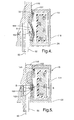
- leakage flux "A”, FIG. 4 is directed across the air gap defined by the conical armature end tapered wall 168 and the cylindrical wall 162 and wall 160 of the center pole member 120 providing additional opening force in the axial direction.
- the additional opening force provided in this range of armature motion results in improved actuator response from a given current input.
- flux "B”, FIG. 5 is directed across secondary gaps defined by the associated frustoconical surfaces 166 and conical surface of tapered wall 168 of the axial chamber 152 and the armature 146, respectively.
- FIG. 2 shows the linear solenoid 18 in a closed position as might be encountered when an engine is idling when no cam phase adjustment is required.
- the coil 130 In the closed position, the coil 130 remains in a non-energized state and, as a result, no force creating magnetic flux fields are established.
- a biasing member 112 biases the armature 146 and attached rod 92 towards the secondary pole piece 134 in the closed position to thereby seat the armature 146 against open end 60 of the actuator housing 20.
- biasing member 112 may be a spring as depicted, but is not limited thereto.
- a current signal is transmitted to the coil 130 to establish a magnetic field across the radial air gap 148 between the outer cylindrical wall 164 of the armature 146 and the inner wall 152 of the center pole member 120 of the primary pole piece 118.
- leakage flux "A" is directed across the air gap defined by the conical armature end tapered wall 168 and the cylindrical wall 162 and tapered wall 160 of the center pole member 120 providing additional opening force in the opening direction.
- the magnetic fields cause an opening force to be exerted on the armature 146 in the direction of the rod axis 93 and opposing the bias exerted by the biasing member 112, and the rod head 94, in the closing direction.
- the armature 146 and the attached actuator assembly 14 moves axially such that the rod member is urged to alter the cam phase.
- flux "B" shown in FIG. 5 is directed across the secondary gap defined by the associated conical surfaces 168 and frustoconical chamber 166 surfaces of the axial chamber 152 and the armature 146. Closure of the gap resulting from continued movement of the armature 146 in the rod opening direction, rapidly increases the magnetic force.
- FIG. 6 illustrates the limited linear range, travel distance and force of current cam phase solenoid design. It will be recognized that thirteen curves relative to Force vs.Tavel are shown, wherein each curve corresponds to a certain number of amp-turns ranging from 200 amp-tum (A-T) to 1400 A-T on coil 130.
- the current cam phase design has a substantially linear portion from about 0.5 mm to about 2.0 mm for each curve.
- the maximum travel distance is about 3.0mm while the maximum force is 18N with 1400 A-T.
- results obtained include an increase of the linear and dynamic range of the flow curve, an increase in the magnetic force profile and increase in travel distance (i.e., 4mm).
- results obtained include an increase of the linear and dynamic range of the flow curve, an increase in the magnetic force profile and increase in travel distance (i.e., 4mm).
- the exemplary solenoid design provides a maximum force of more than 30N with 1200 A-T.
- the linear range is expanded and magnetic force profile is increased while improving input power requirement compared with present designs.
- the present disclosure discloses a linear solenoid for cam phase actuators that provides a wide linear range using existing known components for such a linear solenoid on a vehicle.
- the components are preferably made from low carbon steel, while the rod material is preferably made from non-magnetic stainless steel.
- the linear solenoid disclosed herein is discussed for use with cam phasers, it will be noted that the contemplated use is of the large stroke linear solenoid may be implemented in many other applications requiring a large force, large stroke and linear magnetic package design.
Landscapes
- Engineering & Computer Science (AREA)
- Physics & Mathematics (AREA)
- Electromagnetism (AREA)
- Mechanical Engineering (AREA)
- General Engineering & Computer Science (AREA)
- Power Engineering (AREA)
- Electromagnets (AREA)
- Magnetically Actuated Valves (AREA)
Abstract
Description
Claims (40)
- A electromagnetic solenoid assembly (18) having a magnetic circuit configured to provide a linear magnetic force to an actuation assembly (14) comprising:wherein said primary pole piece (118) having a center pole member (120) including a cylindrical inner wall (162), open at a first end, for receiving said moveable armature (146) and said rod member (92), said armature (146) and said cylindrical inner wall (162) defining a fixed, radially extending, primary air gap (180) for flux passage thereacross, and an outer wall (160) extending in an outward taper from said first, open end of said center pole member (120) to a second end of said center pole member (120), said outwardly tapering wall (160) operable to increase the mass of the pole piece (118) through which said magnetic circuit operates as said armature (146) moves from said first, open end of said center pole member (120) towards said second end, said inner cylindrical wall (162) further including an axially inwardly extending flat section (171), an inner wall (167) extending in an inward taper extending from said flat section (171) towards said armature (146) adjacent said second end of said center pole member (120), said inner wall (167) operable with an associated conical portion (168) formed on a periphery of said moveable armature (146) to define a secondary air gap (182) for flux passage thereacross as said armature (146) approaches said second end of said pole piece (118), and operable to increase axial force on said armature (146) in relation to said primary air gap (180) for flux passage.a primary pole piece (118);a secondary pole piece (134) in magnetic communication with said primary pole piece (118), said primary and secondary pole pieces (134) defining an axial chamber (152); andan armature (146), associated with a rod member (92), said armature (146) and rod member (92) being moveable in said chamber (152) and in operable communication with the actuation assembly (14),
- The solenoid assembly (18) of claim 1, said conical portion (168) formed on said periphery of said moveable armature (146) operable with said inner wall (167) to define a passage for leakage flux as said armature (146) moves in said axial chamber (152) to further increase axial force on said armature (146) to maintain a substantially linear magnetic profile for a distance traveled by said armature (146).
- The solenoid assembly (18) of claim 1, wherein said inner wall (167) extends from said flat section (171) to a height of about one half of a height of said outwardly tapering wall (160) extending from said flat section (171).
- The solenoid assembly (18) of claim 1, wherein said outwardly tapering wall (160) tapers outwardly and down away from said armature (146) at an angle of about 69 degrees to about 73 degrees relative to said flat section (171).
- The solenoid assembly (18) of claim 1, wherein said inner wall (167) tapers inwardly and upward toward said armature (146) at an angle of about 53 degrees to about 59 degrees relative to said flat section (171).
- The solenoid assembly (18) of claim 1, wherein said conical portion (168) formed on said periphery of said moveable armature (146) includes an axially inward taper from the periphery of said armature (146), said inward taper defining a frustoconical cavity (166) on a bottom surface of said armature (146).
- The solenoid assembly (18) of claim 6, wherein said inward taper forms an angle of about 62 degrees to about 66 degrees relative to said flat section (171).
- The solenoid assembly (18) of claim 1, wherein a bias is applied to said armature (146), wherein said bias includes a biasing member (112) operably connected to said armature (146), said biasing member (112) biasing said armature (146) away from said primary pole piece (118).
- The solenoid assembly (18) of claim 1, wherein said magnetic circuit includes a coil (130) disposed around said armature (146) for operably energizing the solenoid (18).
- The solenoid assembly (18) of claim 1, wherein further movement of said armature (146) toward said primary pole piece (118) is operably prevented when said conical portion (168) on said periphery of said armature (146) meets said flat section (171) and said inner wall (167).
- A solenoid assembly (18) for cam phasing in an internal combustion engine comprising:wherein said primary pole piece (118) having a center pole member (120) including a cylindrical inner wall (162), open at a first end, for receiving said moveable armature (146) and said rod member (92), said armature (146) and said cylindrical inner wall (162) defining a fixed, radially extending, primary air gap (180) for flux passage thereacross, and an outer wall (160) extending in an outward taper from said first, open end of said center pole member (120) to a second end of said center pole member (120), said outwardly tapering wall (160) operable to increase the mass of the pole piece (118) through which said magnetic circuit operates as said armature (146) moves from said first, open end of said center pole member (120) towards said second end, said inner cylindrical wall (162) further including an axially inwardly extending flat section (171), an inner wall (167) extending in an inward taper extending from said flat section (171) towards said armature (146) adjacent said second end of said center pole member (120), said inner wall (167) operable with an associated conical portion (168) formed on a periphery of said moveable armature (146) to define a secondary air gap (182) for flux passage thereacross as said armature (146) approaches said second end of said pole piece (118), and operable to increase axial force on said armature (146) in relation to said primary air gap (180) for flux passage.an electromagnetic solenoid actuator having a magnetic circuit including primary and secondary pole pieces (118, 134) defining an axial chamber (152); andan armature (146), associated with a rod member (92), said armature (146) and rod member (92) being moveable in said chamber (152),
- The solenoid assembly (18) of claim 11, said conical portion (168) formed on said periphery of said moveable armature (146) operable with said inner wall (167) to define a passage for leakage flux as said armature (146) moves in said axial chamber (152) to further increase axial force on said armature (146) to maintain a substantially linear magnetic profile for a distance traveled by said armature (146).
- The solenoid assembly (18) of claim 11, wherein said inner wall (167) extends from said flat section (171) to a height of about one half of a height of said outwardly tapering wall (160) extending from said flat section (171).
- The solenoid assembly (18) of claim 11, wherein said outwardly tapering wall (160) tapers outwardly and down away from said armature (146) at an angle of about 69 degrees to about 73 degrees relative to said flat section (171).
- The solenoid assembly (18) of claim 11, wherein said inner wall (167) tapers inwardly and upward toward said armature (146) at an angle of about 53 degrees to about 59 degrees relative to said flat section (171).
- The solenoid assembly (18) of claim 11, wherein said conical portion (168) formed on said periphery of said moveable armature (146) includes an axially inward taper from the periphery of said armature (146), said inward taper defining a frustoconical cavity (166) on a bottom surface of said armature (146).
- The solenoid assembly (18) of claim 16, wherein said inward taper forms an angle of about 62 degrees to about 66 degrees relative to said flat section (171).
- The solenoid assembly (18) of claim 11, wherein a bias is applied to said armature (146), wherein said bias includes a biasing member (112) operably connected to said armature (146), said biasing member (112) biasing said armature (146) away from said primary pole piece (118).
- The solenoid assembly (18) of claim 11, wherein said magnetic circuit includes a coil (130) disposed around said armature (146) for operably energizing the solenoid (18).
- The solenoid assembly (18) of claim 11, wherein further movement of said armature (146) toward said primary pole piece (118) is operably prevented when said conical portion (168) on said periphery of said armature (146) meets said flat section (171) and said inner wall (167).
- A cam phaser assembly for cam phasing in an internal combustion engine comprising:wherein said primary pole piece (118) having a center pole member (120) including a cylindrical inner wall (162), open at a first end, for receiving said moveable armature (146) and said rod member (92), said armature (146) and said cylindrical inner wall (162) defining a fixed, radially extending, primary air gap (180) for flux passage thereacross, and an outer wall (160) extending in an outward taper from said first, open end of said center pole member (120) to a second end of said center pole member (120), said outwardly tapering wall (160) operable to increase the mass of the pole piece (118) through which said magnetic circuit operates as said armature (146) moves from said first, open end of said center pole member (120) towards said second end, said inner cylindrical wall (162) further including an axially inwardly extending flat section (171), an inner wall (167) extending in an inward taper extending from said flat section (171) towards said armature (146) adjacent said second end of said center pole member (120), said inner wall (167) operable with an associated conical portion (168) formed on a periphery of said moveable armature (146) to define a secondary air gap (182) for flux passage thereacross as said armature (146) approaches said second end of said pole piece (118), and operable to increase axial force on said armature (146) in relation to said primary air gap (180) for flux passage.a cam phaser module (10) for an engine head having a vane phaser sub-assembly, and an actuator assembly (14) having a solenoid assembly (18), the solenoid assembly (18) including;an electromagnetic solenoid actuator having a magnetic circuit including primary and secondary pole pieces (118, 134) defining an axial chamber (152); andan armature (146), associated with a rod member (92), said armature (146) and rod member (92) being moveable in said chamber (152),
- The cam phaser assembly of claim 21, said conical portion (168) formed on said periphery of said moveable armature (146) operable with said inner wall (167) to define a passage for leakage flux as said armature (146) moves in said axial chamber (152) to further increase axial force on said armature (146) to maintain a substantially linear magnetic profile for a distance traveled by said armature (146).
- The cam phaser assembly of claim 21, wherein said inner wall (167) extends from said flat section (171) to a height of about one half of a height of said outwardly tapering wall (160) extending from said flat section (171).
- The cam phaser assembly of claim 21, wherein said outwardly tapering wall (160) tapers outwardly and down away from said armature (146) at an angle of about 69 degrees to about 73 degrees relative to said flat section (171).
- The cam phaser assembly of claim 21, wherein said inner wall (167) tapers inwardly and upward toward said armature (146) at an angle of about 53 degrees to about 59 degrees relative to said flat section (171).
- The cam phaser assembly of claim 21, wherein said conical portion (168) formed on said periphery of said moveable armature (146) includes an axially inward taper from the periphery of said armature (146), said inward taper defining a frustoconical cavity (166) on a bottom surface of said armature (146).
- The cam phaser assembly of claim 26, wherein said inward taper forms an angle of about 62 degrees to about 66 degrees relative to said flat section (171).
- The cam phaser assembly of claim 21, wherein a bias is applied to said armature (146), wherein said bias includes a biasing member (112) operably connected to said armature (146), said biasing member (112) biasing said armature (146) away from said primary pole piece (118).
- The cam phaser assembly of claim 21, wherein said magnetic circuit includes a coil (130) disposed around said armature (146) for operably energizing the solenoid (18).
- The cam phaser assembly of claim 21, wherein further movement of said armature (146) toward said primary pole piece (118) is operably prevented when said conical portion (168) on said periphery of said armature (146) meets said flat section (171) and said inner wall (167).
- A method to extend the stroke and linear magnetic force acting on a moveable armature (146) in a solenoid assembly (18) relative to a primary pole piece (118), the method comprising:configuring the armature (146) from a solid cylinder material having a bottom surface cavity formed therein; andconfiguring a secondary pole piece (134) in magnetic communication with said primary pole piece (118), said primary and secondary pole pieces (118, 134) defining an axial chamber (152); wherein said primary pole piece (118) having a center pole member (120) including a cylindrical inner wall (162), open at a first end, for receiving said moveable armature (146), said armature (146) and said cylindrical inner wall (162) defining a fixed, radially extending, primary air gap (180) for flux passage thereacross, and an outer wall (160) extending in an outward taper from said first, open end of said center pole member (120) to a second end of said center pole member (120), said outwardly tapering wall (160) operable to increase the mass of the pole piece (118) through which said magnetic circuit operates as said armature (146) moves from said first, open end of said center pole member (120) towards said second end, said inner cylindrical wall (162) further including an axially inwardly extending flat section (171), an inner wall (167) extending in an inward taper extending from said flat section (171) towards said armature (146) adjacent said second end of said center pole member (120), said inner wall (167) operable with an associated conical portion (168) formed on a periphery of said moveable armature (146) to define a secondary air gap (182) for flux passage thereacross as said armature (146) approaches said second end of said pole piece (118), and operable to increase axial force on said armature (146) in relation to said primary air gap (180) for flux passage.
- The method of claim 31, said conical portion (168) formed on said periphery of said moveable armature (146) operable with said inner wall (167) to define a passage for leakage flux as said armature (146) moves in said axial chamber (152) to further increase axial force on said armature (146) to maintain a substantially linear magnetic profile for a distance traveled by said armature (146).
- The method assembly of claim 31, wherein said inner wall (167) extends from said flat section (171) to a height of about one half of a height of said outwardly tapering wall (160) extending from said flat section (171).
- The method of claim 31, wherein said outwardly tapering wall (160) tapers outwardly and down away from said armature (146) at an angle of about 69 degrees to about 73 degrees relative to said flat section (171).
- The method of claim 31, wherein said inner wall (167) tapers inwardly and upward toward said armature (146) at an angle of about 53 degrees to about 59 degrees relative to said flat section (171).
- The method of claim 31, wherein said conical portion (168) formed on said periphery of said moveable armature (146) includes an axially inward taper from the periphery of said armature (146), said inward taper defining a frustoconical cavity (166) on a bottom surface of said armature (146).
- The method of claim 36, wherein said inward taper forms an angle of about 62 degrees to about 66 degrees relative to said flat section (171).
- The method of claim 31, wherein a bias is applied to said armature (146), wherein said bias includes a biasing member (112) operably connected to said armature (146), said biasing member (112) biasing said armature (146) away from said primary pole piece (118).
- The method of claim 31, wherein said magnetic circuit includes a coil (130) disposed around said armature (146) for operably energizing the solenoid (18).
- The method of claim 31, wherein further movement of said armature (146) toward said primary pole piece (118) is operably prevented when said conical portion (168) on said periphery of said armature (146) meets said flat section (171) and said inner wall (167).
Applications Claiming Priority (2)
| Application Number | Priority Date | Filing Date | Title |
|---|---|---|---|
| US10/222,120 US6615780B1 (en) | 2002-08-16 | 2002-08-16 | Method and apparatus for a solenoid assembly |
| US222120 | 2002-08-16 |
Publications (2)
| Publication Number | Publication Date |
|---|---|
| EP1391589A2 true EP1391589A2 (en) | 2004-02-25 |
| EP1391589A3 EP1391589A3 (en) | 2007-12-05 |
Family
ID=27788778
Family Applications (1)
| Application Number | Title | Priority Date | Filing Date |
|---|---|---|---|
| EP03077389A Withdrawn EP1391589A3 (en) | 2002-08-16 | 2003-07-30 | Solenoid assembly for a hydraulic valve |
Country Status (2)
| Country | Link |
|---|---|
| US (1) | US6615780B1 (en) |
| EP (1) | EP1391589A3 (en) |
Cited By (2)
| Publication number | Priority date | Publication date | Assignee | Title |
|---|---|---|---|---|
| EP1848013A4 (en) * | 2005-02-09 | 2011-03-02 | Isuzu Motors Ltd | Proportional solenoid and flow control valve employing it |
| CN103282979A (en) * | 2010-10-20 | 2013-09-04 | Eto电磁有限责任公司 | Electromagnetic actuating apparatus |
Families Citing this family (35)
| Publication number | Priority date | Publication date | Assignee | Title |
|---|---|---|---|---|
| US6805331B2 (en) | 2001-12-07 | 2004-10-19 | Delphi Technologies, Inc. | Electromagnetically energized actuator |
| US7240894B2 (en) * | 2003-05-30 | 2007-07-10 | Borgwarner Inc. | Pulse width modulated solenoid |
| US7209020B2 (en) * | 2003-06-09 | 2007-04-24 | Borgwarner Inc. | Variable force solenoid |
| US6899313B2 (en) * | 2003-06-25 | 2005-05-31 | Delphi Technologies, Inc. | Magnetic actuator and method |
| US6877526B2 (en) * | 2003-07-02 | 2005-04-12 | Delphi Technologies, Inc. | Magnetic actuator and method |
| US7051992B2 (en) * | 2003-08-25 | 2006-05-30 | Delphi Technologies, Inc. | Tubeless actuator with reduced secondary air gap |
| EP1725829B1 (en) * | 2004-03-08 | 2015-07-22 | Brandt G. Taylor | Induction sensor |
| US7124720B2 (en) * | 2004-03-25 | 2006-10-24 | Ford Global Technologies, Llc | Permanent magnet electromagnetic actuator for an electronic valve actuation system of an engine |
| JP4285354B2 (en) * | 2004-07-26 | 2009-06-24 | 株式会社デンソー | Linear solenoid and solenoid valve |
| JP4823554B2 (en) * | 2005-04-19 | 2011-11-24 | 新電元メカトロニクス株式会社 | Electromagnetic actuator |
| US7688169B2 (en) * | 2005-05-31 | 2010-03-30 | Minebea Co., Ltd. | Long-proportional-stroke force motor |
| US20060272714A1 (en) * | 2005-06-03 | 2006-12-07 | Conrado Carrillo | Magnetic circuit design for linear actuator with small coil diameter |
| JP2007078048A (en) * | 2005-09-13 | 2007-03-29 | Aisin Seiki Co Ltd | solenoid valve |
| US20080266038A1 (en) * | 2007-04-24 | 2008-10-30 | Eaton Corporation | Solenoid assembly |
| US8106734B2 (en) * | 2007-04-25 | 2012-01-31 | Saia-Burgess, Inc. | Adjustable mid air gap magnetic latching solenoid |
| US8248195B2 (en) * | 2007-08-10 | 2012-08-21 | Keihin Corporation | Flat electromagnetic actuator |
| DE102007054652A1 (en) * | 2007-11-16 | 2009-05-20 | Schaeffler Kg | Electromagnetic actuator of a solenoid valve and method of making such actuator |
| EP2182531B1 (en) * | 2008-10-29 | 2014-01-08 | Sauer-Danfoss ApS | Valve actuator |
| DE102008059012A1 (en) * | 2008-11-26 | 2010-05-27 | Schaeffler Kg | Electromagnetic actuator for a hydraulic directional control valve and method for its assembly |
| DE102009006355A1 (en) * | 2009-01-28 | 2010-07-29 | Schaeffler Technologies Gmbh & Co. Kg | Proportional magnet for a hydraulic directional valve and method for its production |
| US8585014B2 (en) * | 2009-05-13 | 2013-11-19 | Keihin Corporation | Linear solenoid and valve device using the same |
| JP2011077355A (en) * | 2009-09-30 | 2011-04-14 | Keihin Corp | Linear solenoid and valve device using the same |
| DE102011003054B4 (en) * | 2011-01-24 | 2014-05-22 | Zf Friedrichshafen Ag | Electromagnetically actuated actuator, in particular for an adjustable damping valve of a vibration damper |
| US8643452B2 (en) * | 2011-04-07 | 2014-02-04 | Indimet Inc. | Solenoid housing with elongated center pole |
| TWI474350B (en) * | 2011-06-10 | 2015-02-21 | Nat Inst Chung Shan Science & Technology | Proportional electromagnet device |
| JP5427210B2 (en) * | 2011-07-05 | 2014-02-26 | 本田技研工業株式会社 | Solenoid and solenoid valve |
| JP5655771B2 (en) * | 2011-09-15 | 2015-01-21 | 株式会社デンソー | Electromagnetic actuator |
| CN103021689B (en) * | 2011-09-26 | 2016-12-28 | 德昌电机(深圳)有限公司 | Electromagnetic driver |
| DE102013206897A1 (en) * | 2013-04-17 | 2014-10-23 | Kendrion (Villingen) Gmbh | Electromagnetic actuator |
| DE102013225392A1 (en) * | 2013-12-10 | 2015-06-11 | Robert Bosch Gmbh | Electromagnet of an electromagnetically actuated fluid valve |
| US9753443B2 (en) * | 2014-04-21 | 2017-09-05 | Synerject Llc | Solenoid systems and methods for detecting length of travel |
| US9997287B2 (en) * | 2014-06-06 | 2018-06-12 | Synerject Llc | Electromagnetic solenoids having controlled reluctance |
| CN107076127B (en) | 2014-06-09 | 2019-11-12 | 新尼杰特公司 | Method and apparatus for cooling solenoid coil of solenoid pump |
| BE1024608B1 (en) * | 2016-09-30 | 2018-05-02 | Safran Aero Boosters S.A. | PROPORTIONAL ELECTROMAGNETIC ACTUATOR VALVE |
| WO2020204137A1 (en) * | 2019-04-04 | 2020-10-08 | イーグル工業株式会社 | Capacity control valve |
Family Cites Families (14)
| Publication number | Priority date | Publication date | Assignee | Title |
|---|---|---|---|---|
| US4604600A (en) * | 1983-12-23 | 1986-08-05 | G. W. Lisk Company, Inc. | Solenoid construction and method for making the same |
| JPH02129476A (en) | 1988-11-09 | 1990-05-17 | Aisin Aw Co Ltd | Pressure regulating valve |
| US4921208A (en) * | 1989-09-08 | 1990-05-01 | Automatic Switch Company | Proportional flow valve |
| US5497738A (en) * | 1992-09-03 | 1996-03-12 | Borg-Warner Automotive, Inc. | VCT control with a direct electromechanical actuator |
| EP0701054A3 (en) | 1994-09-09 | 1996-06-12 | Gen Motors Corp | Linear displacement solenoid actuator for an exhaust gas recirculation valve |
| JP3601554B2 (en) | 1995-08-11 | 2004-12-15 | アイシン・エィ・ダブリュ株式会社 | Solenoid pressure regulator |
| US5836001A (en) * | 1997-09-08 | 1998-11-10 | Mpc Products Corporation | Solenoid having multistage plunger |
| JP2000130629A (en) | 1998-10-23 | 2000-05-12 | Aisin Seiki Co Ltd | Spool valve type solenoid valve |
| US6308672B1 (en) | 1999-08-05 | 2001-10-30 | Delphi Technologies, Inc. | Front-mounting cam phaser module |
| US6189519B1 (en) | 1999-08-23 | 2001-02-20 | Delphi Technologies, Inc. | Short stroke solenoid actuated EGR valve |
| US6289748B1 (en) | 1999-11-23 | 2001-09-18 | Delphi Technologies, Inc. | Shaft torque sensor with no air gap |
| US6538543B2 (en) * | 2000-02-24 | 2003-03-25 | Delphi Technologies, Inc. | Particle-impeding and ventilated solenoid actuator |
| US6347616B1 (en) | 2000-05-10 | 2002-02-19 | Delphi Technologies, Inc. | Solenoid valve for a vehicle carbon canister |
| JP2005098310A (en) * | 2000-09-29 | 2005-04-14 | Nok Corp | Linear solenoid and solenoid valve |
-
2002
- 2002-08-16 US US10/222,120 patent/US6615780B1/en not_active Expired - Fee Related
-
2003
- 2003-07-30 EP EP03077389A patent/EP1391589A3/en not_active Withdrawn
Cited By (2)
| Publication number | Priority date | Publication date | Assignee | Title |
|---|---|---|---|---|
| EP1848013A4 (en) * | 2005-02-09 | 2011-03-02 | Isuzu Motors Ltd | Proportional solenoid and flow control valve employing it |
| CN103282979A (en) * | 2010-10-20 | 2013-09-04 | Eto电磁有限责任公司 | Electromagnetic actuating apparatus |
Also Published As
| Publication number | Publication date |
|---|---|
| EP1391589A3 (en) | 2007-12-05 |
| US6615780B1 (en) | 2003-09-09 |
Similar Documents
| Publication | Publication Date | Title |
|---|---|---|
| US6615780B1 (en) | Method and apparatus for a solenoid assembly | |
| US5779220A (en) | Linear solenoid actuator for an exhaust gas recirculation valve | |
| US5117213A (en) | Electromagnetically operating setting device | |
| US6681806B2 (en) | Solenoid valve | |
| US6883544B2 (en) | Solenoid valve with improved magnetic attractive force | |
| US5730091A (en) | Soft landing electromechanically actuated engine valve | |
| KR101512871B1 (en) | Electromagnetic actuating unit of a solenoid valve, and method for the prodution of such an actuating unit | |
| US5647311A (en) | Electromechanically actuated valve with multiple lifts and soft landing | |
| JPH0658047B2 (en) | Valve drive controller for internal combustion engine | |
| US5765513A (en) | Electromechanically actuated valve | |
| US5692463A (en) | Electromechanically actuated valve with multiple lifts | |
| US6257182B1 (en) | Electromagnetic drive system for engine valve | |
| US5645019A (en) | Electromechanically actuated valve with soft landing and consistent seating force | |
| JP2023531083A (en) | solenoid valve | |
| US6390078B1 (en) | Two stage concentric EGR valves | |
| EP0492557B1 (en) | Valve timing control system of internal combustion engine | |
| US6082315A (en) | Electromagnetic valve actuator | |
| US6205964B1 (en) | Damping device for movable masses, preferably for electromagnetic systems | |
| JP2005176595A (en) | Electromagnetic valve actuator system | |
| US9416691B2 (en) | Internal-combustion engine having a system for variable actuation of the intake valves, provided with an electrically actuated valve having two ways and three positions | |
| US6817592B2 (en) | Electromagnetic valve actuator with soft-seating | |
| US6298812B1 (en) | Valve driving apparatus provided in an internal combustion engine | |
| EP1046804B1 (en) | Cylinder head for internal combustion engine | |
| JP2004056852A (en) | Electromagnetic actuator | |
| US10927719B2 (en) | Variable cam timing phaser having two central control valves |
Legal Events
| Date | Code | Title | Description |
|---|---|---|---|
| PUAI | Public reference made under article 153(3) epc to a published international application that has entered the european phase |
Free format text: ORIGINAL CODE: 0009012 |
|
| AK | Designated contracting states |
Kind code of ref document: A2 Designated state(s): AT BE BG CH CY CZ DE DK EE ES FI FR GB GR HU IE IT LI LU MC NL PT RO SE SI SK TR |
|
| AX | Request for extension of the european patent |
Extension state: AL LT LV MK |
|
| PUAL | Search report despatched |
Free format text: ORIGINAL CODE: 0009013 |
|
| AK | Designated contracting states |
Kind code of ref document: A3 Designated state(s): AT BE BG CH CY CZ DE DK EE ES FI FR GB GR HU IE IT LI LU MC NL PT RO SE SI SK TR |
|
| AX | Request for extension of the european patent |
Extension state: AL LT LV MK |
|
| 17P | Request for examination filed |
Effective date: 20080605 |
|
| AKX | Designation fees paid |
Designated state(s): DE FR GB |
|
| 17Q | First examination report despatched |
Effective date: 20081120 |
|
| STAA | Information on the status of an ep patent application or granted ep patent |
Free format text: STATUS: THE APPLICATION IS DEEMED TO BE WITHDRAWN |
|
| 18D | Application deemed to be withdrawn |
Effective date: 20090331 |