EP1391419B1 - Gripper and method of manufacturing the gripper - Google Patents
Gripper and method of manufacturing the gripper Download PDFInfo
- Publication number
- EP1391419B1 EP1391419B1 EP01917728A EP01917728A EP1391419B1 EP 1391419 B1 EP1391419 B1 EP 1391419B1 EP 01917728 A EP01917728 A EP 01917728A EP 01917728 A EP01917728 A EP 01917728A EP 1391419 B1 EP1391419 B1 EP 1391419B1
- Authority
- EP
- European Patent Office
- Prior art keywords
- gripping
- screw
- gripper
- base member
- holder
- Prior art date
- Legal status (The legal status is an assumption and is not a legal conclusion. Google has not performed a legal analysis and makes no representation as to the accuracy of the status listed.)
- Expired - Lifetime
Links
Images





Classifications
-
- B—PERFORMING OPERATIONS; TRANSPORTING
- B25—HAND TOOLS; PORTABLE POWER-DRIVEN TOOLS; MANIPULATORS
- B25J—MANIPULATORS; CHAMBERS PROVIDED WITH MANIPULATION DEVICES
- B25J15/00—Gripping heads and other end effectors
- B25J15/04—Gripping heads and other end effectors with provision for the remote detachment or exchange of the head or parts thereof
- B25J15/0475—Exchangeable fingers
-
- B—PERFORMING OPERATIONS; TRANSPORTING
- B25—HAND TOOLS; PORTABLE POWER-DRIVEN TOOLS; MANIPULATORS
- B25B—TOOLS OR BENCH DEVICES NOT OTHERWISE PROVIDED FOR, FOR FASTENING, CONNECTING, DISENGAGING, OR HOLDING
- B25B9/00—Hand-held gripping tools other than those covered by group B25B7/00
-
- B—PERFORMING OPERATIONS; TRANSPORTING
- B25—HAND TOOLS; PORTABLE POWER-DRIVEN TOOLS; MANIPULATORS
- B25B—TOOLS OR BENCH DEVICES NOT OTHERWISE PROVIDED FOR, FOR FASTENING, CONNECTING, DISENGAGING, OR HOLDING
- B25B9/00—Hand-held gripping tools other than those covered by group B25B7/00
- B25B9/02—Hand-held gripping tools other than those covered by group B25B7/00 without sliding or pivotal connections, e.g. tweezers, onepiece tongs
-
- B—PERFORMING OPERATIONS; TRANSPORTING
- B25—HAND TOOLS; PORTABLE POWER-DRIVEN TOOLS; MANIPULATORS
- B25J—MANIPULATORS; CHAMBERS PROVIDED WITH MANIPULATION DEVICES
- B25J15/00—Gripping heads and other end effectors
- B25J15/08—Gripping heads and other end effectors having finger members
- B25J15/12—Gripping heads and other end effectors having finger members with flexible finger members
-
- B—PERFORMING OPERATIONS; TRANSPORTING
- B25—HAND TOOLS; PORTABLE POWER-DRIVEN TOOLS; MANIPULATORS
- B25J—MANIPULATORS; CHAMBERS PROVIDED WITH MANIPULATION DEVICES
- B25J7/00—Micromanipulators
Definitions
- the present invention provides a gripper as defined in claim 1.
- the base member attached to the holder member is disengaged from the second engagement portion of the holder member, and the shared portion of the gripping member is removed from the other end of the magnetic member by pulling it with a stronger force than a magnetic adsorption of the magnetic member. Accordingly, there is the effect that the base member having the gripping member can be easily removed from the holder member.
- the gripping finger 103 expanded as shown in Fig. 3 is symmetrical with respect to a dotted line O, and is bent downward on the paper along a broken line L, bent upward on the paper along a broken line M, and bent downward on the paper along a broken line N to form the gripping finger 103 as shown in Fig. 4 .
- the gripping finger 103 has the shared portion 103g in the central portion, each leg portion 103f of the gripping finger 103 being formed with a slit (first slit) 103s in the center and a cut-away end portion 103t on either outer side.
- the gripper 100 as constituted above can perform the substantially same operation as the conventional gripper.
- the slip-off prevention piece 103n of the finger 103 abuts against the surface of the base member 110 to act as a stopper Accordingly, the shared portion 103g of the finger 103 is restrained in the amount of movement, thereby:preventing the V-character sides 103v of the gripping finger 103 from being contacted and pressed to deform the V-character sides 103v.
Landscapes
- Engineering & Computer Science (AREA)
- Mechanical Engineering (AREA)
- Robotics (AREA)
- Manipulator (AREA)
Abstract
Description
- The present invention relates to a gripper for use in conveying or assembling a minute part with improvements in replacement operation of a gripping finger, and more specifically to a gripper known from
WO-A-0045999 - The conventional gripper will be described below with reference to
Fig. 10 as disclosed in said prior art documentWO-A-0045999 Fig. 10 , the gripper 1 has a grippingfinger 10 for gripping or releasing a minute object and having three V-character pieces 10v of substantial V shape, aconversion portion 20 for converting the rotation of amotor shaft 12a of amotor 12 into translation motion, theconversion portion 20 being connected to a sharedportion 10g of the grippingfinger 10, aconnection portion 30 for connecting theconversion portion 20 and the sharedportion 10g of the grippingfinger 10, acase portion 40 for accommodating themotor 12, theconversion portion 20 and theconnection portion 30, and afixing portion 50 for fixing afixing pawl 10t of the grippingfinger 10 to thecase portion 40. - The
conversion portion 20 comprises ascrew axis 22 for fitting and securing themotor shaft 12a of themotor 12 and having amale screw 22a around the outer circumference thereof, and anut 26 for inserting thescrew axis 22 and having a hollow portion formed with afemale screw 26a to be mated with themale screw 22a, in which the rotation of themotor shaft 12a of themotor 12 is converted into translation motion of thenut 26. - The
connection portion 30 is formed with a protrudingportion 26c having a tapped hole centrally at the top end of thenut 26, in which the sharedportion 10g of the grippingfinger 10 is secured into this tapped hole by ascrew 32. - The
case portion 40 is formed of acylindrical case 41 for receiving themotor 12 and a part of thescrew axis 22, alid 43 for closing a right end face of thecase 41, and aholder member 45 engaged with a left end face of thecase 41, in which theholder member 45 is like a barrel having a through hole, with a substantially trapezoidal shape in cross section, and has afemale screw 45b on the outer face of ahollow portion 45a at the top end. - The
fixing portion 50 is formed with a male screw for mating with thefemale screw 45b of theholder member 45 on an external circumferential face of acylindrical presser ring 53. Thefixing pawl 10t of the grippingfinger 10 abuts onto thehollow portion 45a of theholder member 45, and thefixing portion 50 is securely pressed by thepresser ring 53. - In addition, the fixing pawl may be engaged into an engagement portion of a base member engaged into the holder member.
- Referring to
Fig. 10 , the operation of the gripper as constituted above will be described below. First of all, themotor 12 is powered on, and then themotor shaft 12a of themotor 12 is rotated, so that this rotation is transmitted via thescrew axis 22 to thenut 26 to move thenut 26 in a right direction as indicated inFig. 10 . - Along with this, the shared
portion 10g of the grippingfinger 10 is forcibly displaced by the same amount of displacement in the same direction, and the grippingfinger 10 is subjected to a bending moment, so that the V-character pieces are bent at the top end portion in the direction coming closer to each other and closed to grip an object. - On the contrary, if the rotation of the
motor 12 is reversed, with this rotation, thenut 26 is translated via thescrew axis 22 in a reverse direction, and the sharedportion 10g of the grippingfinger 10 is also translated by the same amount of displacement in the consistent manner, so that the top end portions of the grippingfinger 10 release the object. - However, if the gripping object of the gripping
finger 10 is spherical, thegripping finger 10 may be composed of three fingers as above described, but if the object is like a square pole, the gripping finger must be composed of two fingers (not shown) to grip the object appropriately. Also, the grippingfinger 10 must be exchanged due to expiration of life, if a predetermined number of operation times is exceeded. - Such an exchange is perform in such a way that the
screw 32 is firstly turned by a screwdriver (not shown) to release engagement of the protrudingportion 26c of thenut 26 into the tapped hole, and then thepresser ring 53 is turned by a spanner (not shown) to unscrew theholder member 45 from thefemale screw 45b, thereby detaching the grippingfinger 10. - In order to attach the gripping
finger 10 on theholder member 45, thescrew 32 is tightened into the tapped hole of the protrudingportion 26c by the screwdriver, thepresser ring 53 is turned by the spanner and mated with thefemale screw 45b of theholder member 45. Thus, there was a problem that the exchange operation of the grippingmember 10 was troublesome. - In addition, in the case where the gripper 1 is employed for an end effector of a robot, and particularly is attached vertically downward at the top end portion of a scalar robot to be actuated horizontally, the gripper 1 can not be disposed sideways or upward, resulting in a problem that the exchange operation of the gripping
finger 10 alone was troublesome. - This invention is aimed at providing a gripper and its manufacturing method in which a gripping member is easily attached.
- Accordingly, the present invention provides a gripper as defined in claim 1.
- With this constitution of the gripper, the gripping member is engaged with the first engagement portion of the base member, the base member is engaged with the second engagement portion of the holder member, and the shared portion of the gripping member is magnetically connected to the other end of the magnetic member, whereby the gripping member can be engaged with the base member, and the base member attached to the holder member in simple manner.
- Further, the base member attached to the holder member is disengaged from the second engagement portion of the holder member, and the shared portion of the gripping member is removed from the other end of the magnetic member by pulling it with a stronger force than a magnetic adsorption of the magnetic member. Accordingly, there is the effect that the base member having the gripping member can be easily removed from the holder member.
- Advantageously, the gripper comprises an actuator for actuating a movement portion which translates, a gripping member having at least two sides of substantial V shape, a shared portion for joining one ends of said two sides, and the other ends of said sides, a base member having a bore punched in the central portion thereof, an engagement portion for engaging an end portion of said gripping member thereto, and at least two protrusion pieces around outer circumference, a holder member having at least two grooves for engaging said protrusion pieces of said base member detachably therewith, and a hollow portion, which is penetrated, a magnetic member made of a permanent magnet, the magnetic member inserted into said hollow portion of said holder member, the magnetic member one end of which is connected to said movement portion, and a connection member one end of which is adsorbed magnetically to the other end of said magnetic member, the connection member the other end of which is connected to the shared portion of said gripping member, the connection member inserted into said hollow portion of said holder member.
- With this constitution of the gripper, the end portion of the gripping member is engaged with the engagement portion of the base member, the protrusion piece of the base member is engaged with the groove of the holder member, and the shared portion of the gripping member is connected to the other end of the connection member, whereby the gripping member and the base member are attached to the connection member and the holder member, respectively.
- The protrusion piece of the base member is removed from the groove of the holder member, and the shared portion of the gripping member is pulled to detach one end of the connection member from the other end of the magnetic member, whereby the gripping member and the base member are removed from the connection member and the holder member, respectively. Accordingly, there is the effect that the gripping member and the base member can be easily removed from the connection member and the holder member, respectively.
- For example, if the protrusion piece of the base member is engaged in the groove provided on the side face of the cylindrical member having the hollow portion into which the gripping member can be inserted in a state where the base member is attached to the holder member, the protrusion piece of the base member is easily removed from the groove of the holder member.
- Advantageously, the gripper is characterized in that a first slit is defined at the other end portion of said gripping member.
- With the constitution of the gripper, there is the effect that if the operator depresses an end portion of the gripping member, for example, the end portion is compressed owing to a spring action, and can be easily engaged with the engagement portion of the base member.
- Advantageously, the gripper is characterized in that said connection member has a tapped hole at the other end portion thereof, and the screw member is inserted into a bore of the shared portion of said gripping member and is tightened into the tapped hole of said connection member.
- With the constitution of the gripper, there is the effect that the shared portion of the gripping member can be simply attached to or detached from the connection member by means of the screw member.
- Advantageously, the gripper is characterized in that said screw member is cylindrical, and further comprises a head portion formed a minus signal shaped or plus signal shaped groove, a screw portion tightened into the tapped hole of said connection member, and a screw preventing portion having a diameter larger than said screw portion and smaller than said head portion and having a length greater than the thickness of said shared portion of said gripping member, said screw preventing portion provided between said head portion and said screw portion.
- With the constitution of the gripper, when the screw member is inserted into the bore of the gripping member, and tightened into the tapped hole of the connection member by a screwdriver, for example, the screw preventing portion prevents the threaded portion of the screw member from proceeding. Accordingly, there is the effect that the gripping member is kept from being deformed due to tightening the screw member beyond the tolerance.
- Advantageously, the gripper is characterized in that said protrusion pieces of said base member define second slits.
- With the constitution of the gripper, when the protrusion piece of the base member with the gripping member is inserted into the groove of the holder member, the protrusion piece acts as a compression spring owing to the second slit provided in the base member.
- Accordingly, there.is the effect that the protrusion piece of the base member with the gripping member is easily inserted into the groove of the holder member.
- Advantageously, the gripper is characterized in that said shared portion of said gripping member has a slip-off prevention piece having a larger diameter than the diameter of the bore of said base member.
- With the constitution of the gripper, when the base member is pulled out of the holder member, the slip-off prevention piece of the gripping member abuts against an upper portion of the inner circumferential face of the base member at a predetermined displacement, even though the shared portion of the base member is pulled. Thus, there is the effect that the shared portion of the gripping member is restrained in the amount of movement, thereby preventing the sides of the gripping member from being contacted and pressed against each other, and being deformed.
- Also, there is the same effect when the gripping member is pulled and detached, because the slip-off prevention piece of the gripping member abuts against an upper portion of the inner circumferential face of the base member.
- The present invention also provides a method for manufacturing a gripper according to claim 8.
- Accordingly, the protrusion piece of the base member can be simply engaged into the engagement hole of the holder member, whereby there is the effect that the base member is easily attached on the holder member.
-
-
Fig. 1 is a front cross-sectional view showing the constitution of a gripper. -
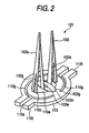
Fig. 2 is a perspective view of a finger unit as shown inFig. 1 . -
Fig. 3 is a plan view showing a state where a gripping finger ofFig. 1 is expanded. -
Fig. 4 is a front cross-sectional view showing the finger unit and a part of a connection portion as shown inFig. 1 . -
Fig. 5 is a plan view showing a base member for fixing an end portion of the gripping finger ofFig. 1 . -
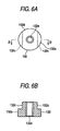
Fig. 6A is a plan view of a connecting nut as shown inFig. 1 , andFig. 6B is a front cross-sectional view of the connecting nut, taken along the arrow b-b inFig. 6A . -
Fig. 7 is a front view of a center screw as shown inFig. 1 . -
Fig. 8 is a front cross-sectional view of a holder member as shown inFig. 1 . -
Fig. 9 is an explanatory view showing an adjuster that is an assembly jig. -
Fig. 10 is a front cross-sectional view showing the conventional gripper. - The preferred embodiments of the present invention will be described below.
- Referring to
Figs. 1 to 8 , an embodiment 1 of this invention will be described below.Fig. 1 is a front cross-sectional view showing the constitution of a gripper.Fig. 2 is a perspective view of a finger unit.Fig. 3 is a plan view showing a state where a gripping finger is expanded.Fig. 4 is a front cross-sectional view showing the finger unit and a part of a connection portion.Fig. 5 is a plan view showing a base member for fixing an end portion of the gripping finger.Fig. 6A is a plan view of a connecting nut.Fig. 6B is a front cross-sectional view of the connecting nut taken along an arrow b-b inFig. 6A .Fig. 7 is a front view of a center screw.Fig. 8 is a front cross-sectional view of a holder member. - In
Fig. 1 , the same or like parts are designated by the same numerals as inFig. 10 . The description of those parts is omitted. - In
Figs. 1 to 8 , agripper 100 has afinger unit 101, amotor 12 as a actuator connected to a sharedportion 103g of agripping finger 103 and having ashaft 12a for translating the sharedportion 103g, aconversion portion 120 for converting the rotation of theshaft 12a of themotor 12 into translation motion, aconnection portion 130 connected to theconversion portion 120 and the sharedportion 103g of thegripping finger 103, and acase portion 140 for accommodating themotor 12, theconversion portion 120 and theconnection portion 130 and fixing thefinger unit 101. - The
finger unit 101 has thegripping finger 103 as a gripping member and abase member 110, as shown inFig. 2 . thegripping finger 103 has two V-character pieces 103v of substantial V shape that are opened or closed when the top end portions are widened by pulling or restoring one end in accordance with a translation displacement to grip a minute object. - The
gripping finger 103 expanded as shown inFig. 3 is symmetrical with respect to a dotted line O, and is bent downward on the paper along a broken line L, bent upward on the paper along a broken line M, and bent downward on the paper along a broken line N to form thegripping finger 103 as shown inFig. 4 . Thegripping finger 103 has the sharedportion 103g in the central portion, eachleg portion 103f of thegripping finger 103 being formed with a slit (first slit) 103s in the center and a cut-awayend portion 103t on either outer side. - The shared
portion 103g of thegripping finger 103 is formed with a slip-off prevention piece 103n having a larger diameter than the diameter of abore 110e of thebase member 110 and with abore 103e punched in the central portion. - The
base member 110 is like a plain washer, and has thebore 110e punched in the center and twoprotrusion pieces 110t provided around the outer circumference, as shown inFig. 5 . Thebase member 110 is provided with twonotches 110c as a first engagement portion that are engaged by holding theleg portions 103f of thefinger 103, as shown inFig. 5 . Theprotrusion piece 110t is provided with aslit 110s (second slit) and formed with acircular slit 110g continuous to theslit 110s and extending to a ring portion of thebase member 110. - The width of the
slits protrusion piece 110t is pressed by holding it from side faces thereof, whereby theprotrusion piece 110t is compressed due to a spring force, and theprotrusion piece 110t is inserted into agroove 145e of theholder member 145 as will be described later and released holding, theprotrusion piece 110t can be restored due to a spring force and engaged in thegroove 145e. - The
circular slit 110g may not be needed depending one the magnitude of spring force - The
notch 110c of thebase member 110 has a substantial T shape as seen in a plan view, and is wider in depth than an opening. The width of thenotch 110c in depth is formed slightly smaller than the width of anend portion 103t of thegripping finger 103 at the top end. Thereby, theend portion 103t is inserted into thenotch 110c by carrying both sides of theleg portion 103f of thegripping finger 103 and abutted against the depth portion of thenotch 110c, and then theleg portion 103f is released to engage theend portion 103t with thenotch 110c. In this manner, thefinger unit 101 is formed. - The
conversion portion 120 has a movingnut 126 as a movement portion that is mated with themale screw 22a of thescrew axis 22 and has afemale screw 126a on the outer face of a hollow portion formed by cutting the rear end, in which the rotation of theshaft 12a of themotor 12 is converted into a translation displacement of the movingnut 126. - The moving
nut 126 has a rectangular outer shape to prevent rotation and is formed with a cylindrical hollow portion 126e at the front end. - The
connection portion 130 has acylindrical magnet 128 as a cylindrical magnetic member made of rare earth magnet, in which thecylindrical magnet 128 has an outer diameter slightly smaller than the bore diameter of the hollow portion 126e in the movingnut 126, with one end portion being inserted into the hollow portion 126e and fixed by adhesives, a connectingnut 132 as a connection member made of magnetic substance such as iron steel that is magnetically adsorbed and fixed on the other end face of thecylindrical magnet 128, and acenter screw 134 inserted into thebore 103e of the sharedportion 103g in thegripping finger 103 and screwed into the tappedhole 132e (seeFig. 6 ) of the connectingnut 132. - In the case where the moving
nut 126 is made of magnetic substance, it is not required that one end portion of thecylindrical magnet 128 is fixed to the hollow portion 126e of the movingnut 126 by adhesives. Because it is fixed by adsorption due to a magnetic suction force of thecylindrical magnet 128. - The connecting
nut 132 is formed like an inverse T shape in cross section and is provided with acylindrical portion 132a and an interposingportion 132d having two flat interposing faces 132c opposed to each other to be easily turned by the spanner, as shown inFig. 6 . - The
center screw 134 as the screw member is provided with ahead portion 134a having aminus groove 134c, ascrew portion 134d mated into the tappedhole 132e of the connectingnut 132, and a cylindricalscrew preventing portion 134f provided between thehead portion 134a and thescrew portion 134d, thescrew preventing portion 134f having a larger diameter than thescrew portion 134d and having a greater length than the thickness of grippingfinger 101 at the end, as shown inFig. 7 . - The screw preventing .
portion 134f is formed to be slightly smaller than the diameter of thebore 103e in thegripping finger 103. This is because thescrew preventing portion 134f is inserted into thebore 103e of the grippingmember 103, and is movable within thebore 103e. - The
groove 134c of thecenter screw 134 may be plus. - The
case portion 140 is formed of alid 43, and aholder member 145 engaged with a left end face of thecase 41 and holding thefinger unit 101 detachably. - The
holder member 145 has formed a top endhollow portion 145m for receiving thecylindrical magnet 128 and thecenter screw 134 in the central portion, which contains theconnection portion 130 and is formed like a barrel with substantially trapezoidal shape in cross section, and a rear endhollow portion 145h for receiving the movingnut 126, as shown inFigs. 1 and8 . - The
holder member 145 is provided, at the top end portion, with a fixingportion 145f, which is formed to be hollow and cylindrical with substantially concave shape in cross section and fixing thebase member 110 of thefinger unit 101. The fixingportion 145f is provided with twogrooves 145e as the second engagement portion, into which theprotrusion piece 110t of thebase member 110 is inserted and fitted. - In a state where the
protrusion piece 110t is fitted into thegroove 145e, a top end of theprotrusion piece 110t is slightly protruded out of the outer circumference of theholder member 145, as shown inFig. 1 . - The
gripper 100 as constituted above can perform the substantially same operation as the conventional gripper. - The assembly of the gripper as constituted above will be described below with reference to
Figs. 1 to 9 . - Referring to
Fig. 9 , an assembly jig will be described below.Fig. 9 is a front cross-sectional view (A), a right side view (B) and a plan view (C) of an adjuster for attaching the finger unit to the finger holder. - In
Fig. 9 , theadjuster 200 is a cylindrical member having abore 200e, having two protrudingportions ends portions grooves protrusion pieces 110t of thebase member 110 in thefinger unit 101. - A
groove 200h has a slightly smaller width than theprotrusion piece 110t of thebase member 110, and is formed corresponding to the position of theprotrusion piece 110t. Agroove 200i is formed to be a slightly smaller width than thegroove 200h. - An operation of attaching or detaching the
finger unit 101 to or from theholder member 145 using theadjuster 200 will be described below. - First of all, when the
finger unit 101, the connectingnut 132 and thecenter screw 134 are not attached inFig. 1 , and when thefinger unit 101 is in a state ofFig. 2 , thescrew portion 134d of thecenter screw 134 is passed through thebore 103e of the sharedportion 103g in thegripping finger 103 and mated into the tappedhole 132e of the connectingnut 132, as shown inFig. 3 . - While the
bore 200e of theadjuster 200 is being put on thegripping finger 103 from the above, thegroove 200h of theadjuster 200 is slidingly pressed on the side face of theprotrusion piece 110t of thebase member 110. Since a pressing force is exerted to interpose theprotrusion piece 110t, theprotrusion pieces 110t are elastically deformed toward each other under the pressure of theadjuster 200, thereby narrowing the gap between theslits 110s, so that the width of theprotrusion piece 110t is equal to that of thegroove 200h of theadjuster 200. - And the
protrusion piece 110t of thebase member 110 is engaged in thegroove 200h. In this engaged state, theprotrusion piece 110t is fitted into thegroove 145e of theholder member 145, and interposed under a predetermined compression force, thereby attaching thefinger unit 101 on theholder member 145. Since the compression force of thegroove 200h of theadjuster 200 is released by fitting theprotrusion piece 110t into thegroove 145e of theholder member 145, thegroove 200h of theadjuster 200 is easily detached from theprotrusion piece 110t of thebase member 110. At the same time, an end face of the connectingnut 132 is magnetically adsorbed onto an end face of thecylindrical magnet 128, thereby completing thegripper 100 as shown inFig. 1 . - On the other hand, in the
gripper 100 as shown inFig. 1 , theprotrusion piece 110t is subjected to a pressure with oneend 200c of theadjuster 200 in contact with thefinger unit 101, and further compressed, while sliding it on the side face of theprotrusion piece 110t of thebase member 110, to be engaged in thegroove 200i of theadjuster 200, whereby theprotrusion piece 110t is disengaged from thegroove 145e of theholder member 145. - If the
adjuster 200 is lifted, thecenter screw 134 and the connectingnut 132 connected to thefinger unit 101 are lifted at the same time, and an end face of the connectingnut 132 is released from the magnetic adsorption with an upper face of thecylindrical magnet 128, whereby thefinger unit 101, thecenter screw 134 and the connectingnut 132 can be easily removed from a main body of thegripper 100. - In lifting the
finger unit 101 by means of the adjuster. 200, the slip-off prevention piece 103n of thefinger 103 abuts against the surface of thebase member 110 to act as a stopper Accordingly, the sharedportion 103g of thefinger 103 is restrained in the amount of movement, thereby:preventing the V-character sides 103v of thegripping finger 103 from being contacted and pressed to deform the V-character sides 103v. - The members described in this specification are only illustrative, and the invention is not limited to those members.
- As described above, the gripper of the present invention is suitable for exchanging the gripping member simply.
Claims (8)
- A gripper comprising:an actuator (12) for actuating a movement portion (126) which translates;a gripping member (103) having at least two sides (103v) of substantial V shape, a shared portion (130g) for joining one end of each of said at least two sides;a holder member (145) having a base member (110) including a first engagement portion (110c) for engaging the other end of each of said at least two sides of said gripping member thereto, said holder member having a second engagement portion (145e) for engaging said base member (110) detachably thereto, and a hollow portion (145m) which is penetrated; anda magnetic member (128) made of a permanent magnet, one end of the magnetic member being connected to one end of said movement portion (126), the other end of the magnetic member being magnetically connected to said shared portion (103g) of said gripping member (103), the magnetic member being inserted into said hollow portion (145m) of said holder member (145).
- A gripper according to claim 1, wherein said base member (110) has a bore (110e) punched in the central portion thereof, and at least two protrusion pieces (110b) around outer circumference;
said holder member (145) has at least two grooves (145e) for engaging said protrusion pieces (110b) of said base member (110) detachably therewith; and the gripper further comprising
a connection member (132) one end of which is adsorbed magnetically to the other end of said magnetic member (128), the other end of the connection member (132) being connected to the shared portion (103g) of said gripping member (103), the connection member being inserted into said hollow portion (145m) of said holder member. - The gripper according to claim 1 or 2, wherein a first slit (103s) is defined at the other end of each of said at least two sides of said gripping member.
- The gripper according to claim 2, further comprising a screw member (134);
wherein said connection member (132) has a tapped hole (132e) at the other end portion thereof; and
wherein the screw member (134) is inserted into a bore (103e) of said shared portion (103g) of said gripping member and is tightened into the tapped hole (132e) of said connection member (132). - The gripper according to claim 4, wherein said screw member (134) is cylindrical, and further comprises a head portion (134a) having a minus signal shaped or plus signal shaped groove (134c), a screw portion (134d) tightened into the tapped hole (132a) of said connection member, and a screw preventing portion (134f) having a diameter larger than said screw portion (134d) and smaller than.said head portion (134a) and having a length greater than the thickness of said shared portion (103g) of said gripping member, said screw preventing portion (134f) being provided between said head portion (134a) and said screw portion (134d).
- The gripper according to claim 2, wherein said protrusion pieces (110t) of said base member define second slits (110s).
- The gripper according to claim 2, wherein said shared portion (103g) of said gripping member has a slip-off prevention piece (103m) having a larger diameter than the diameter of said bore (110e) of said base member.
- A method for manufacturing a gripper including:an actuator (12) for actuating a movement portion (126) which translates;a gripping member (103) having at least two sides (103v) of substantial V-shape, a shared portion (103g) for joining one end of each of said at least two sides;a base member (110) having a bore (110e) punched in the central portion thereof, an engagement portion (110c) for engaging the other end of each of said at least two sides of said gripping member thereto, and at least two protrusion pieces (110t) around outer circumference;a holder member (145) having at least two grooves (145e) for engaging said protrusion pieces (110t) of said base member detachably therewith, and a hollow portion (145m) which is penetrated;a magnetic member (128) made of a permanent magnet, the magnetic member being inserted into said hollow portion (145m) of said holder member, one end of the magnetic member being connected to said movement portion (126); anda connection member (132) one end of which is adsorbed magnetically to the other end of said magnetic member (128), the other end of the connection member being connected to said shared portion (103g) of said gripping member, the connection member being inserted into said hollow portion (145m) of said holder member,the method comprising the steps of engaging the protrusion pieces (110t) of said base member with the grooves (145e) of said holder member (105) by pressing side surfaces of the protrusion pieces (110t) of said base member with a first groove provided on the side face of a cylindrical member having a hollow portion into which said gripping member (103) can be inserted.
Applications Claiming Priority (1)
| Application Number | Priority Date | Filing Date | Title |
|---|---|---|---|
| PCT/JP2001/002791 WO2002081364A1 (en) | 2001-03-30 | 2001-03-30 | Gripper and method of manufacturing the gripper |
Publications (3)
| Publication Number | Publication Date |
|---|---|
| EP1391419A1 EP1391419A1 (en) | 2004-02-25 |
| EP1391419A4 EP1391419A4 (en) | 2010-05-19 |
| EP1391419B1 true EP1391419B1 (en) | 2011-05-04 |
Family
ID=11737206
Family Applications (1)
| Application Number | Title | Priority Date | Filing Date |
|---|---|---|---|
| EP01917728A Expired - Lifetime EP1391419B1 (en) | 2001-03-30 | 2001-03-30 | Gripper and method of manufacturing the gripper |
Country Status (5)
| Country | Link |
|---|---|
| US (1) | US6935666B2 (en) |
| EP (1) | EP1391419B1 (en) |
| JP (1) | JP3843945B2 (en) |
| DE (1) | DE60144581D1 (en) |
| WO (1) | WO2002081364A1 (en) |
Families Citing this family (12)
| Publication number | Priority date | Publication date | Assignee | Title |
|---|---|---|---|---|
| US7083210B2 (en) | 2003-01-15 | 2006-08-01 | Mitsubishi Denki Kabushiki Kaisha | Electric tweezers |
| JP4064299B2 (en) * | 2003-05-22 | 2008-03-19 | 三菱電機株式会社 | Electric tweezers |
| JP4356614B2 (en) * | 2003-05-26 | 2009-11-04 | 三菱電機株式会社 | Electric tweezers |
| CN100339194C (en) * | 2005-11-14 | 2007-09-26 | 哈尔滨工业大学 | Microminiature mobile robot system oriented to precise operation of micro electromechanical system |
| KR100672106B1 (en) * | 2005-11-25 | 2007-01-19 | 미쓰비시덴키 가부시키가이샤 | Electric tweezers |
| CN103291202B (en) * | 2006-05-26 | 2015-05-27 | 森拓设计有限公司 | Screen assembly for a window or door opening |
| CN103433935B (en) * | 2013-09-16 | 2016-02-24 | 胡明建 | The method for designing that magnetic keeps parallel stepping plane of oscillation is driven in a kind of |
| CN103465271B (en) * | 2013-09-23 | 2015-11-11 | 胡明建 | A kind of magnetic keeps the method for designing in parallel stepping rotary oscillation joint |
| US10286565B1 (en) * | 2016-06-13 | 2019-05-14 | Amazon Technologies, Inc. | Skin replacement for robotic manipulator |
| US10307913B2 (en) * | 2017-07-27 | 2019-06-04 | Control & Power Systems, Inc. | Robotic gripper |
| CN108839046A (en) * | 2018-08-21 | 2018-11-20 | 佛山科学技术学院 | A kind of clamp assemblies and flexible retainer |
| EP4342643A1 (en) * | 2022-09-26 | 2024-03-27 | Mettler-Toledo GmbH | Gripping appliance, and systems and method utilizing said gripping appliance |
Family Cites Families (11)
| Publication number | Priority date | Publication date | Assignee | Title |
|---|---|---|---|---|
| SE453168B (en) * | 1982-04-19 | 1988-01-18 | Lennart Palmer | DEVICE FOR REPLACING THE TOOLS OF AN INDUSTRIAL ROBOT |
| US5020964A (en) * | 1989-11-27 | 1991-06-04 | Ford Motor Company | Method and apparatus for robotic transfer of workpieces |
| JPH05293778A (en) | 1992-04-17 | 1993-11-09 | Seiko Instr Inc | Micro gripper |
| JP2560262B2 (en) * | 1994-11-09 | 1996-12-04 | 工業技術院長 | Two-finger micro hand mechanism |
| JPH09108956A (en) * | 1995-10-20 | 1997-04-28 | Mitsubishi Electric Corp | Micro-joint structure and joining method |
| US5884951A (en) * | 1997-05-30 | 1999-03-23 | Eastman Kodak Company | Apparatus and method having short stroke arcuate motion for grasping objects |
| GB2348538B (en) * | 1997-12-15 | 2002-04-17 | Mitsubishi Electric Corp | Microactuator |
| JPH11260480A (en) * | 1998-03-13 | 1999-09-24 | Mitsubishi Electric Corp | Micro component connection device |
| AUPP676798A0 (en) | 1998-10-28 | 1998-11-19 | Sampson, Ronald Spencer | Automatic cut-off pneumatic tyre valve |
| JP3757795B2 (en) | 1999-02-08 | 2006-03-22 | 三菱電機株式会社 | Micro gripper and method for manufacturing micro gripper |
| US7083210B2 (en) * | 2003-01-15 | 2006-08-01 | Mitsubishi Denki Kabushiki Kaisha | Electric tweezers |
-
2001
- 2001-03-30 WO PCT/JP2001/002791 patent/WO2002081364A1/en not_active Ceased
- 2001-03-30 DE DE60144581T patent/DE60144581D1/en not_active Expired - Lifetime
- 2001-03-30 JP JP2002553788A patent/JP3843945B2/en not_active Expired - Fee Related
- 2001-03-30 US US10/296,813 patent/US6935666B2/en not_active Expired - Lifetime
- 2001-03-30 EP EP01917728A patent/EP1391419B1/en not_active Expired - Lifetime
Also Published As
| Publication number | Publication date |
|---|---|
| US6935666B2 (en) | 2005-08-30 |
| JP3843945B2 (en) | 2006-11-08 |
| EP1391419A1 (en) | 2004-02-25 |
| US20030111855A1 (en) | 2003-06-19 |
| DE60144581D1 (en) | 2011-06-16 |
| JPWO2002081364A1 (en) | 2004-07-29 |
| EP1391419A4 (en) | 2010-05-19 |
| WO2002081364A1 (en) | 2002-10-17 |
Similar Documents
| Publication | Publication Date | Title |
|---|---|---|
| EP1391419A1 (en) | Gripper and method of manufacturing the gripper | |
| CN1189291C (en) | Cutter chuck for drill bits | |
| EP1591204B1 (en) | Hand actuable locking clamp | |
| KR890008464A (en) | A method for holding a tamper resistant brake actuator and the head of the actuator in the flange case of the actuator. | |
| JPH041203B2 (en) | ||
| WO2001045905A1 (en) | Top load ratchet wrench | |
| JPH09504476A (en) | Burner holder for mechanized or automated arc welding burner or arc cutting burner, especially mechanical burner or robot burner | |
| JP7274593B2 (en) | CLUTCH DEVICE, DRILL CHUCK, POWER TOOL AND METHOD OF TWO-DIRECTIONAL ROTATING OF DRILL CHUCK | |
| JP7512051B2 (en) | Grippers for industrial manipulators | |
| JPWO2000045999A1 (en) | Microgripper manufacturing method | |
| JP3244059U (en) | ratchet wrench structure | |
| JPH0258073B2 (en) | ||
| US20040093998A1 (en) | Wrench tool having magnet connected thereto | |
| CA2397298A1 (en) | Torque reduction tool | |
| WO1995010394A1 (en) | A pair of pliers | |
| MX2011004595A (en) | Collets for use with valves. | |
| JPH0984305A (en) | Rotor assembly equipment | |
| CN223294034U (en) | Nut fixing device | |
| JP3241325U (en) | E-shaped retaining ring insertion tool | |
| CN210025086U (en) | Conveniently-assembled inner hexagonal screwdriver | |
| CN216781709U (en) | Double-torsion spring disassembling tool | |
| CN217493953U (en) | Pliers | |
| JPH1032916A (en) | Electric wire clamp | |
| EP1075901A1 (en) | Improved hand tool | |
| KR20240052297A (en) | Tool changing arm of automatic tool changing device |
Legal Events
| Date | Code | Title | Description |
|---|---|---|---|
| PUAI | Public reference made under article 153(3) epc to a published international application that has entered the european phase |
Free format text: ORIGINAL CODE: 0009012 |
|
| 17P | Request for examination filed |
Effective date: 20021126 |
|
| AK | Designated contracting states |
Kind code of ref document: A1 Designated state(s): AT BE CH CY DE DK ES FI FR GB GR IE IT LI LU MC NL PT SE TR |
|
| RAP1 | Party data changed (applicant data changed or rights of an application transferred) |
Owner name: MITSUBISHI DENKI KABUSHIKI KAISHA |
|
| A4 | Supplementary search report drawn up and despatched |
Effective date: 20100419 |
|
| RIC1 | Information provided on ipc code assigned before grant |
Ipc: B25J 9/10 20060101ALI20100413BHEP Ipc: B25J 15/04 20060101ALI20100413BHEP Ipc: B81B 7/00 20060101AFI20021023BHEP Ipc: B25J 7/00 20060101ALI20100413BHEP |
|
| GRAP | Despatch of communication of intention to grant a patent |
Free format text: ORIGINAL CODE: EPIDOSNIGR1 |
|
| RBV | Designated contracting states (corrected) |
Designated state(s): CH DE GB LI |
|
| RIN1 | Information on inventor provided before grant (corrected) |
Inventor name: TADA, TOMOYOSHI,MITSUBISHI DENKI K.K. Inventor name: MURAMATSU, NAOKI,MITSUBISHI DENKI K.K. |
|
| GRAS | Grant fee paid |
Free format text: ORIGINAL CODE: EPIDOSNIGR3 |
|
| GRAA | (expected) grant |
Free format text: ORIGINAL CODE: 0009210 |
|
| AK | Designated contracting states |
Kind code of ref document: B1 Designated state(s): CH DE GB LI |
|
| REG | Reference to a national code |
Ref country code: GB Ref legal event code: FG4D |
|
| REG | Reference to a national code |
Ref country code: CH Ref legal event code: EP |
|
| REF | Corresponds to: |
Ref document number: 60144581 Country of ref document: DE Date of ref document: 20110616 Kind code of ref document: P |
|
| REG | Reference to a national code |
Ref country code: DE Ref legal event code: R096 Ref document number: 60144581 Country of ref document: DE Effective date: 20110616 |
|
| PLBE | No opposition filed within time limit |
Free format text: ORIGINAL CODE: 0009261 |
|
| STAA | Information on the status of an ep patent application or granted ep patent |
Free format text: STATUS: NO OPPOSITION FILED WITHIN TIME LIMIT |
|
| 26N | No opposition filed |
Effective date: 20120207 |
|
| REG | Reference to a national code |
Ref country code: DE Ref legal event code: R097 Ref document number: 60144581 Country of ref document: DE Effective date: 20120207 |
|
| REG | Reference to a national code |
Ref country code: CH Ref legal event code: PL |
|
| PG25 | Lapsed in a contracting state [announced via postgrant information from national office to epo] |
Ref country code: LI Free format text: LAPSE BECAUSE OF NON-PAYMENT OF DUE FEES Effective date: 20120331 Ref country code: CH Free format text: LAPSE BECAUSE OF NON-PAYMENT OF DUE FEES Effective date: 20120331 |
|
| REG | Reference to a national code |
Ref country code: GB Ref legal event code: 746 Effective date: 20140325 |
|
| REG | Reference to a national code |
Ref country code: DE Ref legal event code: R084 Ref document number: 60144581 Country of ref document: DE Effective date: 20140326 |
|
| PGFP | Annual fee paid to national office [announced via postgrant information from national office to epo] |
Ref country code: GB Payment date: 20150325 Year of fee payment: 15 |
|
| GBPC | Gb: european patent ceased through non-payment of renewal fee |
Effective date: 20160330 |
|
| PG25 | Lapsed in a contracting state [announced via postgrant information from national office to epo] |
Ref country code: GB Free format text: LAPSE BECAUSE OF NON-PAYMENT OF DUE FEES Effective date: 20160330 |
|
| PGFP | Annual fee paid to national office [announced via postgrant information from national office to epo] |
Ref country code: DE Payment date: 20170321 Year of fee payment: 17 |
|
| REG | Reference to a national code |
Ref country code: DE Ref legal event code: R119 Ref document number: 60144581 Country of ref document: DE |
|
| PG25 | Lapsed in a contracting state [announced via postgrant information from national office to epo] |
Ref country code: DE Free format text: LAPSE BECAUSE OF NON-PAYMENT OF DUE FEES Effective date: 20181002 |