Technical Field
This invention relates to a laser thermal (heat) transfer
recording method whereby a full-color image with a high
resolution is formed using laser beams. More specifically,
it relates to a laser thermal transfer recording method which
is useful in forming a color proof (DDCP: direct digital color
proof) or a mask image by laser recording derived from digital
image signals in the filed of printing.
Background Art
In the field of graphic art, a printing plate is baked
with the use of a set of color separation films constructed
from an original color copy using lith films. Prior to the
main printing (i.e., the practical printing procedure), it has
been a practice to form a color proof from the color separation
films in order to check errors in the color separation step
and examine the necessity for color correction, etc. It is
desired that such a color proof has a high resolution power
so as to allow high reproducibility of medium contrast images,
a high process stability and the like. To obtain a color proof
closely similar to the actual printed matter, it is preferable
to employ the same materials as used in the actual printed matter
(for example, printing paper as a base material and pigments
as colorants) in the color proof. To form a color proof, it
is also highly desirable to use a dry method without resort
to any developers.
As a dry method for forming a color proof, there has been
developed a recording system wherein a color proof is directly
formed from digital signals with the recent popularization of
the electronic systems in the pre-printing step (in the pre-press
industry). These electronic systems aim at, in particular,
forming color proofs with high image qualities. In general,
dot images of 150 lines per inch or above can be reproduced
thereby. To record a proof with high image qualities from
digital signals, use is made of, as a recording head, laser
beams which can be appropriately modulated depending on digital
signals and by which recording beams can be finely stopped down.
Accordingly, it has been required to develop a recording material
having a high sensitivity to laser beams and showing a high
resolution power enabling the reproduction of highly fine dots.
As recording materials usable in the transfer
image-formation method with the use of laser beams, there are
known hot-melt transfer sheets having a photothermal conversion
layer, which absorbs laser beams and generate heat, and an image
formation layer, in which a pigment is dispersed in other
components such as a hot-melt wax and a binder, on a substrate
in this order (JPA 5-58045). In the image formation method
using these recording materials, the image forming layer is
molten in the parts corresponding to the heat generated from
laser-irradiated region of the photothermal conversion layer
and thus transferred onto the image receptor sheet provided
on the transfer sheet. Thus the transferred image is formed
on the image receptor sheet.
JPA 6-219052 discloses a thermal transfer sheet having
a photothermal conversion layer containing a photothermal
conversion substance, an extremely thin heat removable layer
(0.03 to 0.3 µm) and an image forming layer containing a colorant
on a substrate in this order. In this thermal transfer sheet,
the binding force between the image formation layer and the
photothermal conversion layer mediated by the above-described
heat removable layer is weakened by irradiation with laser beams
and thus a very fine image is formed on the image receptor sheet
provided on the thermal transfer sheet. The phenomenon
so-called "abbration" is utilized in the image formation method
with the use of the above-described thermal transfer method.
More particularly speaking, the heat removable layer is partly
decomposed and vaporized in the laser-irradiated regions. As
a result, the adhesiveness between the image receptor layer
and the photothermal conversion layer is weakened in these
regions and thus the image receptor layer in these regions is
transferred onto the image receptor sheet laminated thereon.
These image forming methods have advantages such that
a printing paper having an image receptor layer (an adhesive
layer) can be used as an image receptor sheet material, a
multicolor image can be easily obtained by successively
transferring images with different colors on the image receptor
sheet, and a highly fine image can be easily obtained. Therefore,
these methods are useful in forming color proofs (DDCP: direct
digital color proofs) or highly fine mask images.
To shorten the recording time in recording an image using
laser beams, laser beams consisting of multibeam with the use
of a plural number of laser beams are employed in recent years.
In case of recording an image with the use of an existing thermal
transfer sheet with multibeam laser beams, there sometimes
arises a problem that the transferred image has only an
insufficient density. Aparticularly serious decrease in image
density is observed in high-energy laser recording. As the
results of examinations by the present inventor, it has been
clarified that such a decrease in image density is caused by
uneven transfer occurring in case of high energy laser
irradiation.
In the above-described recording methods, use is made
of one image receptor sheet R and a plural number of thermal
transfer sheets such as K (black), C (cyan), M (magenta) and
Y (yellow). In recording media, it has been a practice to
laminate 20 to 100 sheets of the same type and package. In
case of packaging about 25 sheets as shown in Fig. 10, for example,
recording media 1 of the same type are vacuum-packaged in a
packaging material 3 such as a synthetic resin bag made of,
for example, polyethylene and further packed in a decorative
box 5 made of corrugated fiberboard or the like to give a package
7.
Prior to setting in a recorder, five types of such packages
7, i.e., an image receptor sheet R and thermal transfer sheets
K, C, M and Y are opened. The recording media thus opened are
manually set into a recording medium cassette of the recorder
in the reverse order to the recording order. That is to say,
the thermal transfer sheet Y is first taken out from the packages
7 having been opened and set into the cassette. Subsequently,
the thermal transfer sheets, M, C and K and the image receptor
sheet are similarly set into the cassette. Thus, a plural number
of recording media consisting of the image receptor sheet and
the thermal transfer sheets K, C, M and Y (from top to bottom)
are laminated and set in the cassette. In case of setting a
plural number of recording medium sets, the above-described
procedure is to be repeated.
Disclosure of the Invention
Since recording media of respective types are separately
packaged in existing packages, one recording medium should be
taken out from each of the packages of the image receptor sheet
R and thermal transfer sheets K, C, M and Y having been opened
and set into a cassette. Therefore, individual recording media
are exposed to the outer surroundings and thus the possibility
of the adhesion of foreign materials is elevated. The adhesion
of foreign materials brings about a problem that printing cannot
be normally carried out and there arise defects such as white
spots and uneven ring pattern.
Moreover, the individual recording media should be
manually set into the cassette in the reverse order to the
printing order. Thus, there frequently arises a problem that
the order of color recording is mistaken due to an error in
setting.
Furthermore, the image receptor sheet or the thermal
transfer sheets should be picked up from the recording medium
cassette and transferred into the recorder using a picking up
system such as a rubber roller or a sucking/adsorption system.
During this operation, there arises another problem of
positioning error or jamming.
Under these circumstances, the present invention aims
at providing a laser thermal transfer recording method whereby
an image receptor sheet or thermal transfer sheets can be
transported and fed in a stable state without causing jamming
or positioning error to thereby give an image free from any
defects in the image caused by the adhesion of foreign materials
or mistaken color recording order due to an error in manual
operation.
The above problem can be solved by the following means.
Brief Description of the Drawings
Fig. 1 is a diagram schematically showing the whole
constitution of a recorder adequate for the recording method
according to the present invention.
Fig. 2 is a diagram showing the constitution of the
recording head unit of a recorder adequate for the recording
method according to the present invention.
Fig. 3 is a sectional view of a simple cassette recording
medium in a recorder adequate for the recording method according
to the present invention.
Fig. 4 is a diagram illustrating the lamination form of
a plural number (3 in this case) of recording medium sets each
having recording media laminated in the order of feeding into
a rotary drum for recording.
Fig. 5 is a diagram showing a case wherein an image receptor
layer (film R) is located upward while image formation layers
(films K, C, M and Y) are located downward.
Fig. 6 is a diagram showing another case wherein an image
receptor layer is located downward while image formation layers
are located upward.
Fig. 7 is a diagram illustrating the direction of feeding
recording media into a rotary drum for recording.
Fig. 8 is a diagram showing the recording procedure on
recording media.
Fig. 9 is a diagram showing the constitution of a package
of recording media.
Fig. 10 is a sectional view of an existing package of
recording media.
Fig. 11 (11(a), 11(b) and 11(c)) is a diagram schematically
illustrating the image formation mechanism by film thermal
transfer using laser.
Best Mode for Carrying Out the Invention
In these days of "computer to plate (CTP)", no film is
needed any more and contract proofs are required as a substitute
for proof sheets or analog color proofs. To gain customers'
approval, it is needed to establish a high color reproducibility
agreeing with printed matters or analog color proofs. In order
to fulfill these requirements, there has been developed a DDCP
system wherein pigment-type colorants similar to printing inks
are employed and whereby images can be transferred onto paper
without causing moires, etc. This DDCP system aims at
establishing a large sized (A2/B2) digital direct color proof
system with a high approximation to printed matters wherein
pigment-type colorants similar to printing inks are employed
and whereby images can be transferred onto paper. It is also
intended to form an image having excellent qualities and a stable
transfer density in case of laser-recording with the use of
multibeam laser under different temperature/humidity
conditions by: 1) using, as a thermal transfer sheet, a sheet
not affected by illumination source in comparison with pigment
colorants and printed matters and being excellent in the
sharpness of dots and stability in transferring a colorant film;
2) using, as an image receptor layer, a sheet capable of stably
and surely receiving the image receptor layer of the thermal
transfer sheet; 3) enabling transfer to paper within the scope
of 64 to 157 g/m2 corresponding to art (coated) paper, mat paper,
ultra light weight coated paper and the like and reproducing
fine texture or exact paper whiteness (high key part) ; and 4)
achieving an extremely stable transfer removability. Now, the
total system thus developed will be illustrated involving
greater detained description of the present invention.
The present invention is effective and adequate for a
system of achieving a thermal transfer image consisting of sharp
dots and being applicable to paper transfer and recording
preferably in B2 size (515 mm x 728 mm or above, B2 size: 543
mm x 764 mm) still preferably 594 mm x 841 mm or above.
This thermal transfer image is a dot image having a
resolution of 2400 dpi or above (preferably 2600 dpi or above)
appropriately determined depending on the number of printing
lines. Individual dots have a sharp shape with little bleeding
or defect. Thus, dots over a wide range from high-light to
shadow can be clearly formed, which makes it possible to output
rich dots at the same resolution as in image setters and CTP
setters. Thus, dots and gradation highly approximating printed
matters can be reproduced.
Because of having dots in sharp shape, this thermal
transfer image can correctly reproduce dots corresponding to
laser beams. Moreover, it has recording characteristics
scarcely depending on the ambient temperature/humidity. Thus,
a stable repeated reproducibility can be established both in
hue and density over a wide range of ambient temperature/humidi ty
conditions.
Because of being formed by using color pigments employed
in printing inks and having a high repeated reproducibility,
this thermal transfer image makes it possible to establish a
highly accurate CMS (color management system).
Furthermore, the color hue of this thermal transfer image
can almost agree with color hues of Japan Color, SWOP Color
and the like, i.e., the color hues of printed matters. Moreover,
it can show almost the same color changes as in printed matters
under illumination with different light sources such as a
fluorescent lamp or an incandescent lamp.
Owing to the sharp dot shape, this thermal transfer image
can reproduce fine lines in extremely small characters. Heat
generated by the laser beams is conducted to the transfer
interface without diffusing in the plane direction. As a result,
the image formation layer is sharply broken at the heated
part/unheated part interface. Thus, film formation of the
photothermal conversion layer and the physical properties of
the image formation layer in the thermal transfer sheets are
controlled.
In a simulation, it is estimated the photothermal
conversion layer temperature instantaneously goes up to about
700°C. Therefore, a thin film frequently undergoes deformation
or breakage. The deformation/breakage bring about a practical
trouble that the photothermal conversion layer is transferred
onto the image receptor sheet together with the image formation
layer or the transferred image becomes uneven. To achieve a
definite temperature, on the other hand, the film should contain
a photothermal conversion substance at a high concentration.
Thus, there arises another problem of the sedimentation of a
colorant or migration thereof into the adjacent layer.
From this viewpoint, it is preferable to select an
infrared-absorbing colorant and a heat-tolerant binder such
as a polyimide binder to thereby make the photothermal conversion
layer into a thin film of about 0.5 µm or below in thickness.
In case where the photothermal conversion layer is
deformed or the image formation layer per se is deformed due
to high temperature, the image formation layer transferred onto
the image receptor layer shows an uneven thickness corresponding
to the sub scanning pattern of the laser beams. As a result,
the image also becomes uneven and the apparent transfer density
is lowered. This tendency becomes more remarkable with a
decrease in the thickness of the image formation layer. In
case of a thick image formation layer, on the other hand, the
sharpness of dots is worsened and the sensitivity is lowered
too.
To fulfill these contrary requirements, it is preferable
to relieve the unevenness in transfer by adding a low-melting
substance such as a wax to the image formation layer. It is
also possible to relieve the unevenness in transfer while
sustaining the favorable dot sharpness and sensitivity by adding
inorganic fine particles as a substitute for a binder to give
an adequately elevated layer thickness, thereby ensuring sharp
breakage of the image formation layer at the heated part/unheated
part interface.
In general, low-melting substances such as wax are liable
to ooze out on the image formation layer surface or crystallize
and thus bring about problems in the image qualities or the
stability of the thermal transfer sheets with the passage of
time.
To solve these problems, it is preferable to use a
low-melting substance having a small difference in the SP value
from the polymer of the image formation layer. Thus the
compatibility with the polymer can be elevated so as to prevent
the separation of the low-melting substance from the image
formation layer. It is also preferable to mix and co-melt
together several types of low-melting substances having
different structures to thereby prevent crystallization. As
a result, an image having a sharp dot shape and little unevenness
can be obtained.
Generally speaking, the coating layer of a thermal
transfer sheet absorbs moisture and thus causes changes in the
physical properties and thermal properties thereof. As a result,
there arises humidity-dependency of the recording environment.
To lessen this temperature/humidity-dependency, it is
preferable to use organic solvent systems as the colorant/binder
system of the photothermal conversion layer and the binder system
of the image formation layer. Moreover, it is preferable to
select polyvinyl butylal as the binder in the image receptor
layer and introduce a technique of making the polymer hydrophobic,
thereby lowering the hygroscopicity. Examples of the technique
of making the polymer hydrophobic involve a method of reacting
a hydroxyl group with a hydrophobic group as reported by JPA
8-238858, a method of crosslinking two or more hydroxyl groups
with the use of a film hardener and the like.
In the step of printing by laser-exposure, the image
formation layer is usually heated to about 500°C or above too
and thus some of the conventionally employed pigments undergo
thermal decomposition. This problem can be solved by employing
highly heat-tolerant pigments in the image formation layer.
When an infrared-absorbing colorant migrates from the
photothermal conversion layer to the image formation layer due
to the heat in the printing step, the color hue is changed.
To prevent this phenomenon, it is preferable to design the
photothermal conversion layer with the combined use of an
infrared-absorbing colorant with a binder having a high
retention power as described above.
In high-speed printing, gaps corresponding to the laser
sub scanning intervals are usually formed due to lack in energy.
As discussed above, the heat generation/transduction
efficiency can be elevated by forming the photothermal
conversion layer and the image formation layer into thin films.
To fill up the gaps and elevate the adhesiveness to the image
receptor layer, it is still preferable to add a low-melting
substance to the image formation layer so that the image
formation layer is somewhat fluidized. To elevate the
adhesiveness of the image receptor layer to the image formation
layer and impart a sufficient strength to the transferred image,
it is preferable to employ, for example, polyvinyl butylal as
the binder in the image receptor layer, similar to the image
formation layer.
It is preferable that the image receptor sheet and the
thermal transfer sheets are maintained on a recording medium
support member (preferably in the form of a rotary drum) by
vacuum adhesion. This vacuum adhesion is important, since the
image is formed by controlling the adhesive force between both
sheets and thus the image transfer behaviors are highly sensi tive
in the clearance of the image receptor layer surface of the
image receptor sheet and the image formation layer surface of
the thermal transfer sheet. In case where the clearance between
these materials is enlarged because of foreign materials such
as dirt, there arise defects in the image or uneven image
transfer.
To prevent such defects in the image or uneven image
transfer, it is preferable to form regular projections on the
thermal transfer sheets to thereby smoothen the air flow and
achieve a uniform clearance.
Examples of the method commonly employed in forming
projections on the thermal transfer sheets include
post-treatments such as embossing and addition of a matting
agent to the coating layer. The addition of a matting agent
is preferable from the viewpoints of simplifying the production
process and stabilizing the materials over a long time. The
matting agent should have a size larger than the thickness of
the coating layer. When a matting agent is added to the image
formation layer, there arises a problem that the image in the
parts where the matting agent exists falls off. It is therefore
preferable to add a matting agent having an appropriate particle
size to the photothermal conversion layer. Thus, the image
formation layer per se has an almost uniform thickness and a
defect-free image can be obtained on the image receptor sheet.
To ensure the reproduction of such sharp dots as discussed
above, it is also required to precisely design a recorder. The
recorder to be used herein fundamentally has the same
constitution as conventionally employed laser thermal transfer
recorders. Namely, this constitution is a so-called heat mode
outer drum recording system wherein recording is performed by
irradiating thermal transfer sheets and an image receptor sheet,
which have been fixed on a rotary drum for recording, with a
recording headprovided with aplural number of high-power lasers.
Among all, the following constitution may be cited as a
preferable embodiment.
The image receptor sheet and the thermal transfer sheets
are full-automatically fed from a recording medium cassette.
The image receptor sheet and the thermal transfer sheets are
fixed on the rotary drum for recording by vacuum adsorption.
A large number of vacuum adsorption holes are formed on the
rotary drum for recording and the inside of the drum is evacuated
with a blower, a vacuum pump or the like. Thus the sheets are
adsorbed onto the drum. Since the image receptor sheet is first
adsorbed and then the thermal transfer sheets are further
adsorbed thereon, the thermal transfer sheets have larger in
size than the image receptor sheet. The air among the thermal
transfer sheets and the image receptor sheet, which exerts the
largest effect on the recording performance, is sucked off from
the area of the thermal transfer sheets alone outside the image
receptor sheet.
In this embodiment, a plural number of sheets having a
large area (B2 size) can be superposed and assembled. Therefore,
it is preferable to employ a system whereby air is jetted between
each pair of these sheets so that the sheet fed later is lifted
up.
Figs. 1 and 2 show an example of this constitution.
As Figs. 1 and 2 show, a recording unit of a recorder
21 is provided with a rotary drum 23 for recording serving
as a recording medium support member. The rotary drum 23 for
recording, which is in the form of a hollow cylinder, is held
in a rotatable state on a frame 25 shown in Fig. 2. In the
recorder 21, the rotational direction of this rotary drum 23
for recording is referred to as the main scanning direction.
The rotary drum 23 for recording is connected to the rotary
shaft of a motor and thus driven by the motor.
The recording unit is further provided with a recording
head 27 emitting laser beams Lb. At the position of a thermal
transfer sheet 33 irradiated with the laser beams Lb, the image
formation layer is transferred onto the surface of an image
receptor sheet 31. The recording head 27 linearly shifts in
the direction parallel to the rotary shaft of the rotary drum
23 for recording along a guide rail 35 by a driving mechanism,
which is not shown in the figures. This shifting direction
is referred to as the sub scanning direction. Therefore, a
desired position on the thermal transfer sheet 33 covering the
image receptor sheet 31 can be exposed to the laser beams by
appropriately combining the rotational movement of the rotary
drum 23 for recording and the linear shift of the recording
head 27. Thus, a desired image can be transferred onto the
image receptor sheet 31 by scanning the drawing laser beams
Lb on the thermal transfer sheet 33 and exposing exclusively
positions corresponding to the image data to the laser beams.
A cassette holder 37 is located on the recording medium
setting unit of the recorder 21. A recording medium cassette
41 containing the recording media (i.e., image receptor sheet
31 and the thermal transfer sheets 33) is directly attached
in a removable manner to this cassette holder 37. Since this
recording medium cassette 41 is loaded on the cassette holder
37 in this recorder 21, the recording media are taken out from
the recording medium cassette 41 and fed into the recording
medium support member 23 of the recorder 21.
Fig. 3 is a sectional viewof the recording medium cassette.
This recording medium cassette 41 contains the recording media
including the image receptor sheet 31 and the thermal transfer
sheets 33 laminated in the order of feeding into the rotary
drum 23 for recording. In case of feeding the image receptor
sheet R, a thermal transfer sheet K, a thermal transfer sheet
C, a thermal transfer sheet M and a thermal transfer sheet Y
in this order to the rotary drum 23 for recording, for example,
these sheets are laminated in the order of RKCMY from top to
bottom. From the simple cassette for recording medium attached
to the recorder 21, the recording media are taken out from the
uppermost layer with a pick up mechanism 22 provided in the
recorder 21 and then fed into the recorder 21. Although the
recording media are laminated at certain intervals in this figure,
the recording media are laminated in contact with each other
in practical case.
Since the recorder 21 has the cassette holder 37 in the
cassette attachment unit, it is unnecessary anymore to provide
a space for containing the simple cassette for recording medium
inside of the recorder 21. Thus, the recorder 21 can be
down-sized.
It is preferable that the main body 41a of the recording
medium cassette 41 is made of ametal. In case of using ametallic
main body 41a of the cassette, static electricity, which would
be generated when the laminated recording media shift upon
transportation, can be discharged toward the metallic main body
41a. Thus, static adsorption can be prevented and, in its turn,
the phenomenon of feeding a plural number of sheets at the same
time due to adhesion can be avoided in the step of taking out
the recording medium.
In case of using a main body 41a of the cassette made
of cardboard, the material cost can be reduced. Since such
a main body can be produced at a lower cost, the production
cost can be reduced too. Moreover, use can be made of reclaimed
paper therefor, which contributes to the effective utilization
of resources and lessens undesirable effects on the environment.
Although the recording medium cassette 41 has a low
strength, it can be stably and surely fixed to the recorder
21 by locating on a rigid cassette holder 37. It is therefore
possible to use a recording medium cassette 41 made of a material
having relatively low strength such as cardboard or plastics.
As Fig. 4 shows, a plural number of recording medium sets
(three sets in this case), each having the recording media RKCMY
laminated in the order of feeding into the rotary drum 23 for
recording, may be superposed in the recording medium cassette
41. The number of these sets is an integer. The order of
laminating the recording media in each set (i.e., the recording
order) is exemplified by RKYMC, RYMCK, RCMYK and the like. It
is essentially required that R is the first.
The recording media to be contained in the recording medium
cassette 41 is laminated in such a manner that the image receptor
layer of the image receptor sheet 31 is located in the direction
opposite to the image formation layers of the thermal transfer
sheets 33. That is to say, there are a case wherein the image
receptor layer (the face of film R) is located upward while
the image formation layers (the faces of films K. C, M and Y)
are located downward, and another case wherein the image receptor
layer is located downward while the image formation layers are
located upward.
In the case where the image receptor layer is located
upward while the image formation layers are located downward,
the recording media are fed along the upper periphery of the
rotary drum 23 for recording as shown in Fig. 7(a). Thus, the
image receptor sheet 31 serving as the uppermost layer is first
fixed to the rotary drum 23 for recording. Subsequently, the
thermal transfer sheets 33 are fed into the rotary drum 23 for
recording and thus the image formation layers of the thermal
transfer sheets 33 are superposed on the image receptor layer
of the image receptor sheet 31.
In case where the image receptor layer is located downward
while the image formation layers are located upward, on the
other hand, the recordingmedia are fed along the lower periphery
of the rotary drum 23 for recording as shown in Fig. 7(b). Thus,
the image receptor sheet 31 serving as the uppermost layer is
first fixed to the rotary drum 23 for recording. Subsequently,
the thermal transfer sheets 33 are fed into the rotary drum
23 for recording and thus the image formation layers of the
thermal transfer sheets 33 are superposed on the image receptor
layer of the image receptor sheet 31.
Next, the procedure of taking out the image receptor sheet
and the thermal transfer sheets K, C, M. Y in four colors contained
in the recording medium cassette and forming a desired color
image on the image receptor sheet 31 will be described by
reference to Fig. 8.
As Fig. 1 shows, the recording medium cassette 41 is
attached to the recorder 21 and then the pick up mechanism 22
is driven. Thus, the image receptor sheet 31 serving as the
uppermost layer is fed into the rotary drum 23 for recording
as shown in step 1 in Fig. 8.
In the next step 2, the thermal transfer sheet K is fed
into the rotary drum 23 for recording.
Subsequently, the thermal transfer sheet 33 is laminated
by heating under elevated pressure. This lamination step is
omitted in some cases.
In the next step 3, an image is transferred and output
onto the image receptor sheet 31 based on image data supplied
preliminarily. The supplied image data are separated into
images of individual colors. The laser exposure is carried
out depending on the image data of each color thus separated.
Consequently, the image formation layer of the thermal transfer
sheet 33 is transferred onto the image receptor sheet 31 and
an image is formed on the image receptor sheet 31. The detailed
mechanism of the image formation whereby the image formation
layer of the thermal transfer sheet is transferred onto the
image receptor layer of the image receptor sheet due to the
laser exposure will be illustrated later (Fig. 11).
In step 4, the thermal transfer sheet (K) 33 alone is
removed from the rotary drum 23 for recording. Then it is
confirmed whether or not the color images on all of the thermal
transfer sheets 33 have been transferred. In case of needing
to feed a thermal transfer sheet 33 of another type, the
procedures of the above-described steps 2 to 4 are repeated.
That is to say, the procedures of steps 2 to 4 are repeated
for each of the other thermal transfer sheets C, M and Y (steps
5 to 13). As a result, the images KCMY on the thermal transfer
sheets 33 in four colors are transferred onto the image receptor
sheet 31 and thus a color image is formed on the image receptor
sheet 31.
Next, the image receptor sheet 31 is removed from the
rotary drum 23 for recording. The image having been transferred
onto image receptor sheet 31 thus removed is then further
transferred onto an arbitrary printing paper in an image transfer
unit provided separately. Thus color printing for proofing
is carried out.
By preparing a package containing the image receptor sheet
and the thermal transfer sheets having been laminated in the
order of feeding into the rotary drum 23 for recording packed
therein, the recording media can be set, as contained in the
main body 41a of the cassette, into the recorder 21 at once
after opening the package. It is favorable since the procedure
of manually setting the recording media one by one can be thus
omitted. As a result, the adhesion of foreign materials to
the recording media can be lessened and defects in the image
due to foreign materials can be relieved. It is also possible
to prevent mistaken color recording order due to an error in
manual operation. In addition, a plural number of recording
media can be set at once, which contributes to labor-saving
in the operation of feeding the recording media.
Fig. 9 shows an example of such a package. In case where
the recording media are fed into the rotary drum for recording
15 in the order of R (image receptor sheet), K (black thermal
transfer sheet), C (cyan thermal transfer sheet), M (magenta
thermal transfer sheet) and Y (yellow thermal transfer sheet),
for example, the recording media 53 are laminated in the order
of RKCMY from top to bottom.
The recording media 53 thus laminated are vacuum-packaged
in a packaging material 55 such as a synthetic resin bag made
of, for example, polyethylene and further packed in a decorative
box 57 made of corrugated fiberboard or the like to give a package
51. Although the recording media 53 are laminated at certain
intervals in this figure, the recording media 53 are laminated
in contact with each other in practical case. The order of
laminating the recording media 53 (i.e., the recording order)
is exemplified by RKYMC, RYMCK, RCMYK and the like. It is
essentially required that R is the first.
The recorder 21 as described above further exerts the
following effects.
Since the image receptor sheet 31 is located as the
uppermost layer, the image receptor sheet 31 of the top layer
is first fed into the rotary drum 23 for recording. Namely,
the image receptor sheet 31, which should be fixed first to
the rotary drum 23 for recording, can be always fed first.
Therefore, the thermal transfer sheets 33 of individual colors
can be selectively superposed on the image receptor sheet 31
which has been fixed to the rotary drum 23 for recording.
In case of laminating a plural number of recording medium
sets, a plural number of the recording medium sets can be set
into the recorder 21 at the same time. That is to say, the
image receptor sheet 31 of the first set is fixed to the rotary
drum 23 for recording and then recording is carried out by the
thermal transfer sheets 33 of individual colors. When the image
receptor sheet 31 of the first set on which recording has been
completed is discharged, the image receptor sheet 31 of the
second set is fixed again to the rotary drum 23 for recording.
Then recording is carried out on this image receptor sheet 31
by the thermal transfer sheets 33 of individual colors. After
setting the fist set, namely, recording can be made without
setting the recording media any more. Thus, color images in
the same number of the set number can be formed without manually
setting the recording media. Thus, the steps of setting the
recording media can be reduced, thereby saving labor.
Since the image receptor layer of the image receptor sheet
is located in the direction opposite to the image formation
layers of the thermal transfer sheets 33, the image receptor
layer and the image formation layers can be superposed without
turning over either the image receptor sheet 31 or the thermal
transfer sheets in the course of transporting the image receptor
sheet 31 and the thermal transfer sheets 33. As a result, the
recording media can be quickly fed in the step of feeding and
transporting the recording media. In case of laminating a
plural number of recording medium sets in the recording medium
cassette 41, the image receptor sheets 31 are provided in such
a manner that the image receptor layers 31 are all in the same
direction, while the thermal transfer sheets 33 are laminated
in such a manner that the image formation layers are all in
the same direction.
Since the recording medium cassette 41 is attached to
the recorder 21 in a directly removable manner, it is unnecessary
to set the recording media in a cassette as in existing devices.
Namely, the sets having the recording media laminated in the
order of feeding can be set in a one-touch operation. Thus,
the adhesion of foreign materials to the recording media can
be relived and color recording order errors can be avoided.
Furthermore, the labor in feeding the recording media can be
largely saved thereby.
From the viewpoints of lessening the adhesion of foreign
materials and maintaining the transport of sheets in a favorable
state, it is preferable to use a pressure-sensitive adhesive
roll having a pressure-sensitive adhesive material in some part
of the transport roller commonly employed in the thermal transfer
sheet and image receptor sheet feeding member of the transporting
member.
Using the pressure-sensitive adhesive roll, the surface
of the thermal transfer sheets and the image receptor sheet
can be cleaned.
Examples of the pressure-sensitive adhesive material to
be provided on the surface of the pressure-sensitive adhesive
roll include ethylene-vinyl acetate copolymer, ethylene-ethyl
acrylate copolymer, polyolefin resin, polybutadiene resin,
styrene-butadiene rubber (SBR), styrene-ethylene-butene
styrene copolymer (SEBS), acrylonitrile-butadiene rubber (NBR),
polyisoprene resin (IR), styrene-isoprene copolymer (SIS),
acrylic acid ester copolymer, polyester resin, polyurethane
resin, acrylic resin, butyl rubber and polynorbornene.
The pressure-sensitive adhesive roll comes into contact
with the surface of the thermal transfer sheets and the image
receptor sheet and thus cleans the surface. The contact
pressure thereof is not particularly restricted, so long as
it is in contact with the surface.
It is preferable that the pressure-sensitive adhesive
material to be used in the pressure-sensitive adhesive roll
has a Vickers hardness Hv of 50 kg/mm2 (≒490 MPa) or below from
the viewpoint of sufficiently eliminate dirt (i.e., foreign
materials) and regulate defects in the image.
The term Vickers hardness means the hardness measured
by indenting the test material with a diamond indenter, in the
form of a right pyramid with a square base and an angle of 136
degrees between opposite faces subjected to a static load.
Vickers hardness is determined in accordance with the following
formula.
Hardness Hv = 1.854P/d2 (kf/mm2)
≒ 18.1692P/d2 (MPa).
In the above formula, P stands for the load (kg); and d stands
for distance (mm) between opposite angles of the square in the
recess.
In the present invention, it is also preferable that the
pressure-sensitive adhesive material to be used in the
pressure-sensitive adhesive roll has a modulus of elasticity
at 20°C of 200 kg/mm2 (≒19.6 MPa) or below from the viewpoint
of sufficiently eliminate dirt (i.e., foreign materials) and
regulate defects in the image as described above.
It is preferable that the absolute difference between
the surface roughness Rz of the image formation layer surface
of the thermal transfer sheet and the surface roughness Rz of
the back layer surface thereof is 3.0 or below and the absolute
difference between the surface roughness Rz of the image receptor
layer surface of the image receptor sheet and the surface
roughness Rz of the back layer thereof is 3.0 or below. Owing
to this constitution and the above-described cleaning means,
defects in the image can be prevented, jamming in transportation
can be avoided and, furthermore, the dot gain stability can
be improved.
The term "surface roughness" as used in this description
means an average surface roughness evaluated in 10-grades
corresponding to Rz (maximum height) in JIS. Namely, using
the average face obtained by withdrawing the standard area from
the curved rough face as a standard, the distance between the
average height of from the highest crest to the 5th one and
the average depth of from the deepest root to the 5th one is
input and converted. To measure the surface roughness, use
is made of a three-dimensional roughness meter of the stylus
type (Surfcom 570A-3DF) manufactured by Tokyo Seimitsu K.K.
The measurement is carried out in the longitudinal direction
at cutoff of 0.08 mm, measurement area of 0. 6 x 0.4 mm2, feeding
pitch of 0.005 mm and measuring speed of 0.12 mm/sec.
To further improve the above-described effects, it is
still preferable that the absolute difference between the
surface roughness Rz of the image formation layer surface of
the above-described thermal transfer sheet and the surface
roughness Rz of the back layer surface thereof is 1.0 or below
and the absolute difference between the surface roughness Rz
of the image receptor layer surface of the image receptor sheet
and the surface roughness Rz of the back layer thereof is 1.0
or below.
It is also preferable that the glossiness of the image
formation layer of the thermal transfer sheet is from 80 to
99.
The glossiness largely depends on the smoothness of the
image formation layer and affects the uniformity in the image
formation layer thickness. An image formation layer having
a higher glossiness has the higher uniformity and thus is more
adequate for forming a fine image. However, a higher smoothness
results in the larger resistance during transportation. That
is, there is a trade-off between these factors. When the
glossiness ranges from 80 to 99, both of these factors can be
established in a well-balanced state.
Next, the mechanism of forming a multicolor image by film
thermal transfer with the use of laser will be roughly
illustrated by reference to Fig. 11.
An image formation laminate 30 composed of an image
receptor sheet 20 laminated on the surface of an image formation
layer 16 containing a black (K), cyan (C), magenta (M) or yellow
(Y) pigment is prepared. A thermal transfer sheet 10 has a
substrate 12, a photothermal conversion layer 14 provided
thereon, and the image formation layer 16 further provided
thereon. The image receptor sheet 20 has a substrate 15 and
an image receptor layer 24 provided thereon. On the surface
of the image formation layer 16 of the thermal transfer sheet
10, the image receptor layer 24 is laminated in contact therewith
(Fig. 11(a)). Then the laminate 30 is irradiated with laser
beams corresponding to an image in time series from the side
of the substrate 12 of the thermal transfer sheet 10 of the
laminate 30. Thus, the laser-irradiated part of the
photothermal conversion layer 14 of the thermal transfer sheet
10 generates heat and suffers from a decrease in the adhesion
force to the image formation layer 16 (Fig. 11(b)). Next, the
image receptor sheet 20 is removed from the thermal transfer
sheet 10. Thus, the laser-irradiated region 16' in the image
formation layer 16 is transferred onto the image receptor layer
24 of the image receptor sheet 20 (Fig. 11(c)).
In forming a multicolor image, it is preferable to use
multibeam, inparticular, two-dimensionallyarrangedmultibeam,
as the laser beams to be used in the irradiation. The term
two-dimensionally arranged multibeam means a two-dimensional
planar arrangement wherein a plural number of laser beams are
used in the laser irradiation and the spots of these laser beams
are arranged in such a manner as giving a plural columns along
the main scanning direction and a plural rows along the sub
scanning direction.
Using laser beams with the two-dimensionally arranged
multibeam, the laser recording time can be shortened.
The laser beams to be used herein are not particularly
restricted so long as being multibeam. Namely, use can be made
of gas laser beams such as argon ion laser beams, helium neon
laser beams and helium cadmium laser beams, solid laser beams
such as YAG laser beams, and direct laser beams such as
semiconductor laser beams, colorant laser beams and eximer laser
beams. Alternatively, use can be made of beams obtained by
converting the above-described laser beams into half wave length
through a secondary harmonic element. It is preferable to use
semiconductor laser beams in the present invention from the
viewpoints of output power, easiness in modulation, etc. In
the present invention, it is preferable that the laser
irradiation is carried out under such conditions as giving a
beam diameter on the photothermal conversion layer of from 5
to 50 µm (still preferably from 6 to 30 µm). It is also preferable
that the scanning speed is 1 m/sec or above (still preferably
3 m/sec or above).
In the image formation, it is preferable that the thickness
of the image formation layer in the black thermal transfer sheet
exceeds the image formation layer thicknesses of the yellow,
magenta and cyan thermal transfer sheets and ranges from 0.5
to 0.7 µm. Owing to this design, a decrease in the density
caused by uneven transfer can be prevented in the step of
laser-irradiation of the black thermal transfer sheet.
In case where the image formation layer thickness of the
above-described black thermal transfer sheet is less than 0.5
µm, the image density is largely lowered by uneven transfer
and, therefore, it sometimes becomes impossible to achieve an
imagedensityrequiredasaprintingproof. Since this tendency
becomes more remarkable under a high humidity, a large change
in density arises depending on the environment in some cases.
In case where the above-described layer thickness exceeds 0.7
µm, on the other hand, the transfer sensitivity is lowered in
the laser recording. As a result, it is sometimes observed
that small spots cannot adhere well or fine lines become thinner.
This tendency becomes more remarkable under a low humidity.
Moreover, the resolution power is sometimes worsened. It is
still preferable that the image formation layer thickness of
the above-described black thermal transfer sheet is from 0.55
to 0.65 µm, particularly preferably 0.60 µm.
Furthermore, it is preferable that the thickness of the
image formation layer of the above-described black thermal
transfer sheet is from 0.5 to 0.7 µm and the image formation
layer thickness of each of the above-described yellow, magenta
and cyan thermal transfer sheets is 0.2 µm or more but less
than 0.5 µm.
In case where the image formation layer thickness of each
of the above-described yellow, magenta and cyan thermal transfer
sheets is less than 0.2 µm, the density is lowered due to uneven
transfer in the step of laser recording. In case where the
layer thickness exceeds 0.5 µm, on the other hand, there
sometimes arises a decrease in the transfer sensitivity or
worsening in the resolution power. It still preferably ranges
from 0.3 to 0.45 µm.
It is preferable that the image formation layer of the
above-described black thermal transfer sheet contains carbon
black. This carbon black is preferably a mixture of at least
two types of carbon blacks having different coloring powers,
since the reflective optical density can be controlled thereby
while maintaining the P/B (pigment/binder) ratio within a
specific range.
The coloring power of carbon black may be expressed in
various ways. For example, PVC blackness level reported in
JPA 10-140033 and the like may be cited. The PVC blackness
level is determined by adding carbon black to PVC resin,
dispersing it with a twin-screw roller to make a sheet, and
then evaluating the blackness level of the sample with the naked
eye based on the blackness levels of Carbon Blacks "#40" and
"#45" manufactured by Mitsubishi Chemical referred to
respectively as 1 and 10 scores. Two or more carbon blacks
having different PVC blackness levels can be appropriately
selected and employed depending on the purpose.
Next, a specific example of a method of preparing a sample
will be illustrated.
<Method of preparing sample>
40% by mass of a sample carbon black is added to an LDPE
(low-density polyethylene) resin and kneaded at 115°C for 4
minutes in a 2500 cc Banbury mixer.
Composing conditions:
| LDPE resin |
101.89 g |
| calcium stearate |
1.39 g |
| Irganox 1010 |
0.87 g |
| sample carbon black |
69.43 g |
Next, the mixture is diluted at 120°C in a twin-screw roll
mill until the carbon black concentration amounts to 1% by mass.
Diluted compound preparation conditions:
| LDPE resin | 58.3 g |
| calcium stearate | 0.2 g |
| resin containing 40% by mass of carbon black | 1.5 g |
Then the mixture is formed into a sheet at a slit width
of 0.3 mm and the obtained sheet is cut into chips. Next, a
film of 65±3 µm is formed on a hot plate at 240°C.
To form a multicolor image, a large number of image layers
(image formation layers each having an image formed thereon)
may be repeatedly superposed on a single image receptor sheet
with the use of the above-described thermal transfer sheets
to thereby form a multicolor image as described above.
Alternatively, a multicolor image may be formed by forming images
on the image receptor layers of a plural number of image receptor
sheets and then retransferring the images onto printing paper
or the like.
In the latter case, thermal transfer sheets having image
formation layers containing colorants having different color
hues from each other are prepared and respectively combined
wi th image receptor sheets so as to give four types (four colors:
cyan, magenta, yellow and black) of laminates independently.
Then each laminate is irradiated with laser beams corresponding
to digital signals based on an image via, for example, a color
separation filter. Subsequently, the thermal transfer sheets
are removed from the image receptor sheets. Thus a color
separation image of each color is independently formed on each
image receptor sheet. Then the thus obtained color separation
images are successively laminated on a practical substrate such
as printing paper or a similar substrate prepared separately.
Thus, a multicolor image can be formed.
In the thermal transfer recording with the use of laser
irradiation, laser beams are converted into heat and an image
formation layer containing a pigment is transferred onto an
image receptor sheet with the use of the heat energy to thereby
form an image on the image receptor sheet. Thus, the pigment,
colorant and image formation layer may be in an arbitrary state
such as solid, softened, liquid or gaseous state, preferably
a solid or softened state, in the step of transfer. The thermal
transfer recording with the use of laser irradiation includes,
for example, melt transfer, abbration transfer, sublimation
transfer, etc. conventionally known in the art.
Among all, the above-described film transfer, melt
transfer and abbration transfer are favorable from the viewpoint
that images having color hues similar to printed matters can
be obtained thereby.
To transfer the image receptor sheet having an image
printed by the recorder onto a printing paper (hereinafter
referred to as "paper"), a heat laminator is usually employed.
By applying heat and pressure to the image receptor sheet
superposed on the paper, these sheets adhere to each other.
Then the image receptor sheet is removed from the paper. Thus,
the image receptor layer having the image alone remains on the
paper.
By connecting the above-described recorder to a
plate-making system, a system exerting a color proofing function
can be constructed. In this system, a print having image
qualities as close as possible to the printed matter output
from the plate making data should be output from the
above-described recorder. Therefore, a software for
approximating the colors and dots to the printed matter is needed.
Next, a specific example of the connection will be given.
To take a proof from a printed matter obtained by a plate
making system (for example Celebra manufactured by Fuji
Photofilm), the system is constructed as follows. A CTP
(computer to plate) is connected to the plate making system.
An output printing plate is fed into the printer to give a final
printed matter. The above-described recorder is connected to
the plate making system as a color proof. As a proof drive
software, PD System® is connected between them.
The contone (continuous) data converted into luster data
in the plate making system are converted into binary data for
dots and output to the CTP system followed by printing. On
the other hand, the same contone data are output into the PD
system too. By the PD system, the received data are converted
by a four-dimensional (black, cyan, magenta and yellow) table
so that the colors in the print match with the colors in the
above-described printed matter. Finally, the data are
converted into binary data so as to agree with the dots in the
above-described printed matter and then output to the recorder.
The above-described four-dimensional table is
preliminarily formed experimentally and stored in the system.
The experiment for the formation thereof is as follows. Namely,
an image obtained by printing important color data via the CTP
system and another image output from the recorder via the PD
system are prepared and the color measurement values are compared.
Thus the table is prepared so as to give the minimum difference.
Next, the thermal transfer sheet and the image receptor
sheet appropriately usable in the recorder of the
above-described system will be described.
[Thermal transfer sheet]
The thermal transfer sheet has at least a photothermal
conversion layer and an image formation layer on a substrate
optionally together with other layers, if needed.
(Substrate)
The substrate of the thermal transfer sheet may be made
of any materials without restriction. Various substrate
materials may be used depending on the purpose. It is preferable
that the substrate has a favorable rigidity and a high
dimensional stability and can withstand the heat upon image
formation. Preferable examples of the substrate material
include synthetic resins such as polyethylene terephthalate,
polyethylene-2,6-naphthalate, polycarbonate, polymethyl
methacrylate, polyethylene, polypropylene, polyvinyl chloride,
polyvinylidene chloride, polystyrene, styrene-acrylonitrile
copolymer, polyamide (aromatic or aliphatic), polyimide,
polyamidoimide, polysulfone, etc. Among all, it is preferable
to use biaxially oriented polyethylene terephthalate from the
viewpoints of mechanical strength and dimensional stability
upon heating. In case of using in the formation of a color
proof with the use of laser recording, it is preferable that
the substrate of the thermal transfer sheet is made of a
transparent synthetic resin material permeable to laser beams.
The thickness of the substrate preferably ranges from 25 to
130 µm, still preferably from 50 to 120 µm. It is preferable
that the center line average surface roughness Ra (measured
in accordance with JIS B0601 with, for example, a surface
roughness meter Surfcom manufactured by Tokyo Seiki) of the
substrate in the image formation layer side is less than 0.1
µm. It is preferable that Young's modulus in the length
direction of the substrate is from 200 to 1200 kg/mm2 (≒2 to
12 GPa) while Young's modulus in the width direction thereof
is from 250 to 1600 kg/mm2 (≒2.5 to 16 GPa). The F-5 value
in the length direction of the substrate preferably ranges from
5 to 50 kg/mm2 (≒49 to 490 MPa), while the F-5 value in the
width direction of the substrate preferably ranges from 3 to
30 kg/mm2 (≒29.4 to 294 MPa). Although the F-5 value in the
length direction of the substrate is generally higher than the
F-5 value in the width direction of the substrate, the present
invention is not restricted thereto particularly in case where
the strength in the width direction should be elevated. The
heat compressibility in the length direction of the substrate
is preferably 3% or below, still preferably 1.5% or below at
100°C for 30 minutes and 1% or below, still preferably 0.5%
or below at 80°C for 30 minutes. It is also preferable that
the break strength is from 5 to 100 kg/mm2 (≒490 to 980 MPa)
in both directions and the modulus of elasticity is from 100
to 2000 kg/mm2 (≒0.98 to 19.6 GPa).
To improve the adhesiveness to the photothermal
conversion layer formed thereon, the substrate of the thermal
transfer sheet may be subjected to a surface activation treatment
and/or provided with one or more undercoat layers. Examples
of the surface activation treatment include glow discharge,
corona discharge, etc. As the material of the undercoat layers,
it is preferable to employ one having a high adhesiveness to
both of the substrate and photothermal conversion layer faces,
showing a low heat conductivity and being excellent in heat
tolerance. Examples of such undercoat layer materials include
styrene, styrene-butadiene copolymer, gelatin, etc. The total
thickness of the undercoat layer(s) usually ranges from 0.01
to 2 µm. If needed, the surface of the thermal transfer sheet
in the opposite side to the face having the photothermal
conversion layer thereon may be provided with layers with various
functions such as an antireflective layer or an antistatic layer
or subjected to a surface treatment.
(Back layer)
It is preferable to form a back layer on the surface in
the opposi te side to the face having the photothermal conversion
layer formed thereon of the thermal transfer sheet according
to the present invention. It is preferable that the back layer
is composed of two layers, i.e., a first back layer adjacent
to the substrate and a second layer provided in the opposite
side of the first back layer to the substrate. In the present
invention, it is preferable that the ratio (B/A) of the mass
B of an antistatic agent contained in the second back layer
to the mass A of the antistatic agent contained in the first
back layer is less than 0.3. IN case where the ratio B/A is
0.3 or more, there is observed a tendency that the slipperiness
and powder fall-out from the back layers are worsened.
The thickness C of the first back layer preferably ranges
from 0.01 to 1 µm, still preferably from 0.01 to 0.2 µm. The
thickness D of the second back layer preferably ranges from
0.01 to 1 µm, still preferably from 0.01 to 0.2 µm. The thickness
ratio (C:D) betweenthefirstandsecondlayerspreferablyranges
from 1:2 to 5:1.
As the antistatic agents employed in the first and second
back layers, use can be made of nonionic surfactants such as
polyoxyethylene alkylamine and glycerol fatty acid esters,
cationic surfactants such as quaternary ammonium salts, anionic
surfactants such as alkyl phosphates, amphoteric surfactants,
electrically conductive resins and so on.
It is also possible to use electrically conductive fine
grains as the antistatic agent. Examples of such electrically
conductive fine grains include oxides such as ZnO, TiO2, SnO2,
Al2O3, In2O3, MgO, BaO, CoO, CuO, Cu2O, CaO, SrO, BaO2, PbO, PbO2,
MnO3, MoO3, SiO2, ZrO2, Ag2O, Y2O3, Bi2O3, Ti2O3, Sb2O3, Sb2O5, K2Ti6O13,
NaCaP2O18 and MgB2O5; sulfides such as CuS and ZnS; carbides such
as SiC, TiC, ZrC, VC, NbC, MoC and WC; nitrides such as Si3N4,
TiN, ZrN, VN, NbN and Cr2N; borides such as TiB2, ZrB2, NbB2,
TaB2, CrB, MoB, WB and LaB5; silicides such as TiSi2, ZrSi2,
NbSi2, TaSi2, CrSi2, MoSi2 and WSi2; metal salts such as BaCO3,
CaCO3, SrCO3, BaSO4 and CaSO4; and complexes such as SiN4-SiC
and 9Al2O3-2B2O3. Either one of these compounds or a combination
of two or more thereof may be used. Among all, SnO2, ZnO, Al2O3,
TiO2, In2O3, MgO, BaO and MoO3 are preferable, SnO2, ZnO, In2O3
and TiO2 are still preferable and SnO2 is particularly
preferable.
In case of using thermal transfer sheets in the laser
thermal transfer recording method according to the present
invention, it is preferable that the antistatic agent to be
used in the back layers is substantially transparent so as to
allow the permeation of laser beams.
In case of using an electrically conductive metal oxide
as the antistatic agent, a smaller grain diameter is preferable
to minimize light scattering. However, the grain diameter
should be determined using the refraction index ratio between
the grains and the binder as a parameter. It can be determined
by using Mie's theory. In general, the average grain diameter
ranges from 0.001 to 0.5 µm, preferably from 0.003 to 0.2 µm.
The term average grain diameter as used herein means a value
involving not only the primary grain diameter of the electrically
conductive metal oxide but also grain diameters of higher
structures thereof.
To prevent the adhesion of foreign materials such as dirt
and dust to the thermal transfer sheet causing defects (white
spots, etc.) in the image, it is preferable to control the surface
electrical resistance SRof theback layer surface of the thermal
transfer sheet to 1011 Ω or below at 23°C under 55% RH, still
preferably 1x10⁹ Ω or less.
In addition to the antistatic agent, the first and second
back layers may contain various additives such as a surfactant,
a slipping agent and a matting agent or a binder. It is
preferable that the first back layer contains from 10 to 1000
parts by mass, still preferably from 200 to 800 parts by mass,
of the antistatic agent per 100 parts by mass of the binder.
It is preferable that the second back layer contains from 0
to 300 parts by mass, still preferably from 0 to 100 parts by
mass, of the antistatic agent per 100 parts by mass of the binder.
Examples of the binder to be used in forming the first
and second back layers include homopolymers and copolymers of
acrylic monomers such as acrylic acid, methacrylic acid, acrylic
acid esters and methacrylic acid esters; cellulose-based
polymers such as nitrocellulose, methylcellulose,
ethylcellulose and cellulose acetate; vinyl polymers and vinyl
compound copolymers such as polyethylene, polypropylene,
polystyrene, vinyl chloride-based copolymers, vinyl
chloride-vinyl acetate copolymer, polyvinylpyrrolidone,
polyvinyl butylal and polyvinyl alcohol; condensed polymers
such as polyester, polyurethane and polyamides; rubber-type
thermoplastic polymers such as butadiene-styrene rubber;
polymers obtained by polymerizing and crosslinking
photopolymerizable or heat polymerizable compounds such as
epoxy compounds; melamine compounds and the like.
(Photothermal conversion layer)
Thephotothermal conversion layer contains a photothermal
conversion substance and a binder optionally together with a
matting agent and, if needed, other components.
The photothermal conversion substance is a substance
having a function of converting irradiated light energy into
heat energy. In general, it is a colorant (including pigment,
the same applies hereinafter) capable of absorbing laser beams.
In case of recording an image with infrared laser, it is
preferable to use an infrared-absorbing colorant as the
photothermal conversion substance. Examples of the
above-described colorant include black pigments such as carbon
black, macrocyclic compounds showing absorption in visible to
near-infrared regions such as phthalocyanine and
naphthalocyanine, organic dyes (cyanine dyes such as indolenine
dyes, anthraquinone dyes, azulene dyes, phthalocyanine dyes)
employed as laser absorbers in high-density laser recording
such as photodiscs, and organic metal compound colorants such
as dithiol-nickel complex. Among all, it is preferable to use
a cyanine dyes. This is because it shows a high coefficient
of absorption to light in the infrared region and thus the
photothermal conversion layer can be made into a thin layer
with the use of the same as the photothermal conversion substance.
As a result, the recording sensitivity of the thermal transfer
sheet can be further elevated.
In addition to colorants, use can be made, as the
photothermal conversion substance, granular metallic materials
such as silver halide and inorganic materials.
As the binder to be added to the photothermal conversion
layer, it is preferable to use a resin which has such a strength
as at least allowing the formation of a layer on the substrate
and has a high thermal transfer rate. It is still preferable
to use a heat tolerant resin which is not decomposed even by
the heat generated from the photothermal conversion substance
in recording an image, since a favorable surface smoothness
of the photothermal conversion layer can be maintained even
after high-energy light irradiation. More specifically
speaking, it is preferable to use a resin having a heat
decomposition temperature (i.e., the temperature at which the
mass is reduced by 5% in an air stream under elevating temperature
at a speed of 10°C/min by the TGA (thermogravimetric analysis)
method) of 400°C or above, still preferably a resin having the
above-described heat decomposition temperature of 500°C or above.
It is preferable to use a binder has a glass transition
temperature of from 200 to 400°C, still preferably a binder
having a glass transition temperature of from 250 to 350°C.
In case where the glass transition temperature of the binder
is lower than 200°C, the resultant image sometimes suffers from
fogging. In case where the glass transition temperature is
higher 400°C, the melting properties of the resin are worsened
and thus the production efficiency is sometimes lowered.
It is preferable that the heat tolerance (for example,
heat deformation temperature and heat decomposition
temperature) of the binder in the photothermal conversion layer
is superior to the materials employed in other layers formed
on the photothermal conversion layer.
Specific examples thereof include acrylic acid-based
resins such as polymethyl methacrylate, vinyl resins such as
polycarbonate, polystyrene, vinyl chloride/vinyl acetate
copolymer and polyvinyl alcohol, polyvinyl butylal, polyester,
polyvinyl chloride, polyamide, polyimide, polyether imide,
polysulfone, polyether sulfone, aramide, polyurethane, epoxy
resin, urea/melamine resin, etc. Among all, polyimide resins
are preferable.
In particular, it is preferable to use polyimide resins
represented by the following general formulae (I) to (VII) which
are soluble in organic solvents, since the thermal transfer
sheet productivity can be elevated thereby. These resins also
preferable from the viewpoint of improving the viscosity
stability, long-time storage properties and moisture-proofness
of a coating solution for photothermal conversion layer too.
In the above general formulae (I) and (II), Ar
1 represents
an aromatic group represented by any of the following structural
formulae (1) to (3); and n is an integer of from 10 to 100.
In the above general formulae (III) and (IV), Ar
2
represents an aromatic group represented by any of the following
structural formulae (4) to (7); and n is an integer of from
10 to 100.
In the above general formulae (V) to (VII), n and m are
each an integer of from 10 to 100. In the formula (VI), the
ratio n:m is from 6:4 to 9:1.
To judge whether or not a resin is soluble in an organic
solvent, the resin is dissolved in 100 parts by mass of
N-methylpyrrolidone at 25°C. The dissolution of 10 parts by
mass or more of the resin is employed as a standard. That is
to say, a resin which is dissolved therein in an amount of 10
parts by mass or more is referred to as preferably usable as
the resin for the photothermal conversion layer. It is still
preferable to use a resin 100 parts by mass or more of which
is soluble in 100 parts by mass of N-methylpyrrolidone.
As the matting agent to be added to the photothermal
conversion layer, use is made of inorganic fine grains and
organic fine grains. Examples of the inorganic fine grains
include those made of silica, titanium oxide, aluminum oxide,
zinc oxide, magnesium oxide, metal salts such as barium sulfate,
magnesium sulfate, aluminum hydroxide, magnesium hydroxide and
boron nitride, kaolin, clay, talc, zinc white, lead white,
zeeklite, quartz, diatomaceous earth, barite, bentonite, mica,
synthetic mica, etc. Examples of the organic fine grains
include resin grains such as fluororesin grains, guanamine resin
grains, styrene-acryl copolymer resin grains, silicone resin
grains, melamine resin grains and epoxy resin grains.
The grain diameter of the matting agent generally ranges
from 0.3 to 30 µm, preferably from 0.5 to 20 µm and the addition
level thereof preferably ranges from 0.1 to 100 mg/m2.
If necessary, the photothermal conversion layer may
further contain a surfactant, a thickener, an antistatic agent
and so on.
The photothermal conversion layer can be formed by
dissolving the photothermal conversion substance and the binder,
adding, if necessary, the matting agent and other components
thereto to give a coating solution, applying it on the substrate
and then drying. Examples of the organic solvent in which the
polyimide resin is to be dissolved include n-hexane, cyclohexane,
diglyme, xylene, toluene, ethyl acetate, tetrahydrofuran,
methyl ethyl ketone, acetone, cyclohexanone, 1,4-dioxane,
1,3-dioxane, dimethyl acetate, N-methyl-2-pyrrolidone,
dimethyl sulfoxide, dimethylformamide, dimethylacetamide,
γ-butyrolactone, ethanol, methanol and so on. Application and
drying can be carried out with the use of application and drying
procedures commonly employed. Drying is usually performed at
a temperature of 300°C or below, preferably 200°C or below. In
case of using polyethylene terephthalate as the substrate, it
is preferable to dry at a temperature of 80 to 150°C.
In case where the photothermal conversion layer contains
an excessively small amount of the binder, the cohesive force
of the photothermal conversion layer is lowered. As a result,
the photothermal conversion layer is frequently transferred
together with the formed image onto the image receptor sheet,
thereby causing color mixing in the printed image. In case
where the binder is employed too much, the thickness of the
photothermal conversion layer should be enlarged to achieve
a certain light absorptivity, thereby causing a decrease in
sensitivity in many cases. The mass ratio (on the solid basis)
of the photothermal conversion substance to the binder in the
photothermal conversion layer preferably ranges from 1:20 to
2:1, still preferably from 1:10 to 2:1.
It is also preferable to make the photothermal conversion
layer into a thin film, since the sensitivity of the thermal
transfer sheet can be thus elevated as described above. The
thickness of the photothermal conversion layer preferably
ranges from 0.03 to 1.0 µm, still preferably from 0.05 to 0.5
µm. It is also preferable that the photothermal conversion
layer has an optical density of 0.80 to 1.26 to light of 808
nm in wavelength, since the transfer sensitivity of the image
formation layer can be improved in this case. It is still
preferable that the optical density to light of the
above-described wavelength is from 0. 92 to 1.15. In case where
the optical density at the laser peak wavelength is less than
0.80, the irradiated light cannot be sufficiently converted
into heat and, as a result, the transfer sensitivity is sometimes
lowered. In case where the optical density exceeds 1.26, on
the other hand, the function of the photothermal conversion
layer in recording is affected and thus fogging arises in some
cases.
(Image formation layer)
The image formation layer contains at least a pigment
to be transferred onto the image receptor sheet to form an image.
If necessary, it may further contain a binder for forming the
layer and other components.
In general, pigments are roughly classified into organic
pigments and inorganic pigments. The formers are excellent
particularly in the transparency of coating films, while the
latters are excellent in shielding effect, etc. Thus, an
appropriate one may be selected depending on the purpose. In
case of using the above-described thermal transfer sheets in
print color proofing, it is adequate to use organic pigments
having the same or similar color tones as yellow, magenta, cyan
and black which are generally employed in printing inks.
Moreover, use is sometimes made of metal powders, fluorescent
pigments, etc. Examples of pigments appropriately employed
include azo pigments, phthalocyanine pigments, anthraquinone
pigments, dioxazine pigments, quinacridone pigments,
isoindolinone pigments and nitro pigments. Next, pigments
usable in the image formation layers will be listed, though
the present invention is not restricted thereto.
1) Yellow pigment
Pigment Yellow 12 (C.I. No. 21090)
Example) Permanent Yellow DHG (manufactured by Clariant
Japan), Lionol Yellow 1212B (manufactured by Toyo Ink), Irgalite
Yellow LCT (manufactured by Ciba Speciality Chemicals), Symuler
Fast Yellow GTF (manufactured by Dainippon Ink & Chemicals),
Pigment Yellow 13 (C.I. No. 21100)
Example) Permanent Yellow GR (manufactured by Clariant
Japan), Lionol Yellow 1313 (manufactured by Toyo Ink)
Pigment Yellow 14 (C.I. NO. 21095)
Example) Permanent Yellow G (manufactured by Ciba
Speciality Chemicals), Lionol Yellow 1401-G (manufactured by
Toyo Ink), Seika Fast Yellow 2270 (manufactured by Dainichiseika
Color & Chemical), Symuler Fast Yellow 4400 (manufactured by
Dainippon Ink & Chemicals)
Pigment Yellow 17 (C.I. No. 21105)
Example) Permanent Yellow GG02 (manufactured by Clariant
Japan), Symular Fast Yellow 8GF (manufactured by Dainippon Ink
& Chemicals)
Pigment Yellow 155
Example) Graphtol Yellow 3GP (manufactured by Clariant
Japan)
Pigment Yellow 180 (C.I. No. 21290)
Example) Novoperm Yellow P-HG (manufactured by Clariant
Japan), PV Fast Yellow HG (manufactured by Clariant Japan)
Pigment Yellow 139 (C.I. No. 56298)
Example) Novoperm Yellow M2R 70 (manufactured by Clariant
Japan)
2) Magenta pigment
Pigment Red 57:1 (C.I. No. 15850:1)
Example) Graphtol Rubine L6B (manufactured by Clariant
Japan), Lionol Red 6B-4290G (manufactured by Toyo Ink), Irgalite
Rubine 4BL (manufactured by Ciba Speciality Chemicals), Symuler
Brilliant Carmine 6B-229 (manufactured by Dainippon Ink &
Chemicals),
Pigment Red 122 (C.I. No. 73915)
Example) Hosterperm Pink E (manufactured by Clariant
Japan), Lionogen Magenta 5790 (manufactured by Toyo Ink),
Fastogen Super Magenta RH (manufactured by Dainippon Ink &
Chemicals)
Pigment Red 53:1 (C.I. No. 15585:1)
Example) Permanent Lake Red LCY (manufactured by Clariant
Japan), Symuler Lake Red C conc (manufactured by Dainippon Ink
& Chemicals)
Pigment Red 48:1 (C.I. No. 15865:1)
Example) Lionol Red 2B 3300 (manufactured by Toyo Ink),
Symuler Red NRY (manufactured by Dainippon Ink & Chemicals)
Pigment Red 48:2 (C.I. No. 15865:2)
Example) Permanent Red W2T (manufactured by Clariant
Japan), Lionol Red LX235 (manufactured by Toyo Ink), Symuler
Red 3012 (manufactured by Dainippon Ink & Chemicals)
Pigment Red 48:3 (C.I. No. 15865:3)
Example) Permanent Red 3RL (manufactured by Clariant
Japan), Symuler Red 2BS (manufactured by Dainippon Ink &
Chemicals)
Pigment Red 177 (C.I. NO. 65300)
Example) Cromophtal Red A2B (manufactured by Ciba
Speciality Chemicals)
3) Cyan pigment
Pigment Blue 15 (C.I. No. 74160)
Example) Lionol Blue 7027 (manufactured by Toyo Ink),
Fastogen Blue BB (manufactured by Dainippon Ink & Chemicals)
Pigment Blue 15:1 (C.I. No. 74160)
Example) Hosterperm Blue A2R (manufactured by Clariant
Japan), Fastogen Blue 5050 (manufactured by Dainippon Ink &
Chemicals)
Pigment Blue 15:2 (C.I. No. 74160)
Example) Hosterperm Blue AFL (manufactured by Clariant
Japan), Irgalite Blue BSP (manufactured by Ciba Speciality
Chemicals), Fastogen Blue GP (manufactured by Dainippon Ink
& Chemicals)
Pigment Blue 15:3 (C.I. No. 74160)
Example) Hosterperm Blue B2G (manufactured by Clariant
Japan), Lionol Blue FG7330 (manufactured by Toyo Ink),
Cromophthal Blue 4GNP (manufactured by Ciba Speciality
Chemicals), Fastogen Blue FGF (manufactured by Dainippon Ink
& Chemicals)
Pigment Blue 15:4 (C.I. No. 74160)
Example) Hosterperm Blue BFL (manufactured by Clariant
Japan), Cyanine Blue 700-10FG (manufactured by Toyo Ink),
Irgalite Blue GLNF (manufactured by Ciba Speciality Chemicals),
Fastogen Blue FGS (manufactured by Dainippon Ink & Chemicals)
Pigment Blue 15:6 (C.I. No. 74160)
Example) Lionol Blue ES (manufactured by Toyo Ink)
Pigment Blue 60 (C.I. No. 69800)
Example) Hosterperm Blue RL01 (manufactured by Clariant
Japan), Lionogen Blue 6501 (manufactured by Toyo Ink)
4) Black pigment
Pigment Black 7 (carbon black C.I. No. 77266)
Example) Mitsubishi Carbon Black MA100 (manufactured by
Mitsubishi Chemical), Mitsubishi Carbon Black #5 (manufactured
byMitsubishi Chemical), Black Pearls 430 (manufacturedbyCabot
Co.).
As the pigments usable in the present invention,
appropriate products can be selected by reference to "Ganryo
Binran, ed. by Nihon Ganryo Kijutsu Kyokai, Seibundo Shinkosha,
1989", "COLOUR INDEX, THE SOCIETY OF DYES & COLOURIST, THIRD
EDITION, 1987", etc.
The average grain diameter of the above-described
pigments preferably ranges from 0.03 to 1 µm, still preferably
from 0.05 to 0.5 µm.
When the above-described grain diameter is less than 0.3
µm, the dispersion cost is elevated or the dispersion sets to
gel in some cases. When the grain diameter exceeds 1 µm, on
the other hand, coarse grains in the grain sometimes worsens
the adhesiveness between the image formation layer and the image
receptor layer. In this case, moreover, the transparency of
the image formation layer is sometimes damaged.
As the binder to be used in the image formation layer,
it is preferable to use an amorphous organic polymer having
a softening point of from 40 to 150°C. As the above-described
amorphous organic polymer, use can be made of butylal resin,
polyamide resin, polyethylene imine resin, sulfonamide resin,
polyester polyol resin, petroleum resin, homopolymers and
copolymers of sytrene and its derivatives which may be
substituted such as vinyl toluene, α-methylstyrene,
2-methylstyrene, chlorostyrene, vinylbenzoic acid, sodium
vinylbenzenesulfonate and aminostyrene, homopolymers and
copolymers with other monomers of methacrylic acid esters such
as methyl methacrylate, ethyl methacrylate, butyl methacrylate
and hydroxyethyl methacrylate and methacrylic acid, acrylic
acid esters such as methyl acrylate, ethyl acrylate, butyl
acrylate and α-ethylhexyl acrylate and acrylic acid, dienes
such as butadiene and isoprene, acrylonitrile, vinyl ethers,
maleic acid and maleic acid esters, maleic anhydride, cinnamic
acid and vinyl monomers such as vinyl chloride and vinyl acetate.
Either one of these resins or a mixture of two or more thereof
may be used.
It is preferable that the image formation layer contains
from 30 to 70% by mass of the pigment, still preferably from
30 to 50% by mass. It is also preferable that the image formation
layer contains from 30 to 70% by mass of the resin, still
preferably from 40 to 70% by mass.
As the additional components as described above, the image
formation layer may contain the following components (1) to
(3).
(1) Wax
As the wax, mineral waxes, natural waxes, synthetic waxes,
etc. may be cited. Examples of the above-described mineral
waxes include petroleum waxes such as paraffin wax,
microcrystalline wax, ester wax and oxidized wax, montan wax,
ozokerite wax, ceresine, etc. Among all, paraffin wax separated
from petroleum is preferable. There are marketed various types
of paraffin wax having different melting points.
Examples of the above-described natural waxes include
vegetable waxes such as carnauba wax, candelilla wax, ouricury
wax and esper wax, and animal waxes such as bees wax, insect
wax, shellac and whale wax.
The above-described synthetic waxes, which are generally
employed as lubricants usually consist of higher fatty acid
compounds. Examples of these synthetic waxes are as follows.
1) Fatty acid wax
Linear saturated fatty acids represented by the following
general formula:
CH3(CH2)nCOOH.
In the above formula, n is an integer of from 6 to 28. Specific
examples thereof include stearic acid, behenic acid, palmitic
acid, 12-hydroxystearic acid, azelaic acid, etc.
Moreover, metal (K, Ca, Zn, Mg, etc.) salts of the
above-described fatty acids may be cited.
2) Fatty acid ester wax
Specific examples of the above-described fatty acid
esters include ethyl stearate, lauryl stearate, ethyl behenate,
hexyl behenate, behenyl myristate, etc.
3) Fatty acid amide wax
Specific examples of the above-described fatty acid
amides include stearic acid amide, lauric acid amide, etc.
4) Aliphatic alcohol wax
Linear saturated aliphatic alcohols represented by the
following general formula:
CH3(CH2)nOH.
In the above formula, n is an integer of from 6 to 28. Specific
examples thereof include stearyl alcohol, etc.
Among the synthetic waxes 1) to 4) as listed above, higher
fatty acid amides such as stearic acid amide and lauric acid
amide are particularly appropriate. One of these wax compounds
may be used alone. Alternatively, an adequate combination
thereof may be used if needed.
(2) Plasticizer
As the above-described plasticizer, an ester compound
is preferable. Examples thereof include publicly known
plasticizers such as aliphatic dibasic acid esters, for example,
phthalates such as dibutyl phthalate, di-n-octyl phthalate,
di(2-ethylhexyl) phthalate, dinonyl phthalate, dilauryl
phthalate, butyl lauryl phthalate and butyl benzyl phthalate,
di(2-ethylhexyl) adipate and di(2-eethylhexyl) sebacate,
phosphoric acid triesters such as tricresyl phosphate and
tri(2-ehtylhexyl) phosphate, polyol polyesters such as
polyethylene glycol ester, and epoxy compounds such as epoxy
fatty acid esters. Among these plasticizers, vinyl monomer
esters, in particular, acrylic acid or methacrylic acid esters
are preferable, since they are highly effective in improving
the transfer sensitivity, relieving uneven transfer and
controlling the break elongation.
Examples of the above-described acrylic acid or
methacrylic acid ester compounds include polyethylene glycol
dimethacrylate, 1,2,4-butanetriol trimethacrylate,
trimethylolethane triacrylate, pentaerythritol acrylate,
pentaerythritol tetraacrylate, dipentaerythritol
polyacrylate, etc.
The above-described plasticizer may be a polymer. Among
all, polyesters are preferable from the viewpoints of having
remarkable addition effects and hardly diffusing under the
storage conditions. As the polyester, use may be made of, for
example, sebacate polyesters and adipate polyesters.
The additives to be added to the image formation layer
are not restricted to the above-described ones. Ei ther a single
plasticizer or two or more thereof may be used.
In case where the image formation layer contains the
above-described additives in an excessively large amount, there
sometimes arise problems such as worsening in the resolution
of the transferred image, lowering in the film strength of the
image formation layer per se, or transfer of the unexposed parts
onto the image receptor sheet due to a decrease in the
adhesiveness between the photothermal conversion layer and the
image formation layer. From these points of view, the content
of the above-described wax preferably ranges from 0.1 to 30%
by mass, still preferably from 1 to 20% by mass, based on the
total solid content in the image formation layer. The content
of the above-described plasticizer preferably ranges from 0.1
to 20% by mass, still preferably from 1 to 10% by mass, based
on the total solid content in the image formation layer.
(3) Others
In addition to the above-described components, the image
formation layer may contain a surfactant, inorganic or organic
fine grains (metallic powder, silica gel, etc.), oils (castor
oil, mineral oil, etc.), a thickener, an antistatic agent and
so on. Excluding case of obtaining a black image, energy
required for the transfer can be lessened by using a substance
which absorbs the wavelength of a light source to be used in
the image recording. The substance absorbing the light source
wavelength may be either a pigment or a dye. In case of obtaining
a color image, it is preferable in reproducing colors to use
a dye which has little absorption in the visible region and
largely absorbs the light source wavelength. As examples of
near-red dyes, compounds described in JPA 3-1034 76 may be cited.
The image formation layer can be formed by preparing a
coating solution in which a pigment, the above-described binder,
etc. are dissolved or dispersed, applying it on the photothermal
conversion layer (or on the heat-sensitive removal layer as
will be described hereinafter, if provided on the photothermal
conversion layer) and drying. Examples of the solvent to be
used in the preparation of the coating solution include n-propyl
alcohol, methyl ethyl ketone, propylene glycol monomethyl ether
(MFG), methanol, water, etc. Application and drying can be
carried out with the use of application and drying procedures
commonly employed.
On the photothermal conversion layer of the
above-described thermal transfer sheet, a heat-sensitive
removal layer can be formed. The heat-sensitive removal layer
contains a heat-sensitive material which evolves a gas or
liberates adhering water, etc. under the effect of heat generated
from the photothermal conversion layer to thereby weaken the
adhesion strength between the photothermal conversion layer
and the image formation layer. As the heat-sensitive material,
use may be made of a compound (a polymer or a low-molecular
weight compound) which is decomposed or degenerated per se by
heat to evolve a gas, a compound (a polymer or a low-molecular
weight compound) having a considerably large amount of a highly
vaporizable liquid (for example, water) absorbed or adsorbed
thereby and the like. It is also possible to use these compounds
together.
Examples of the polymer which is decomposed or degenerated
per se by heat to evolve a gas include autooxidizable polymers
such as nitrocellulose, halogenated polymers such as polyolefin
chloride, chlorinated rubber, polychlorinated rubber,
polyvinyl chloride and polyvinylidene chloride, acrylic
polymers having a volatile compound (water, etc.) adsorbed
thereby such as polyisobutyl methacrylate, cellulose esters
having a volatile compound (water, etc.) adsorbed thereby such
as ethyl cellulose, natural high-molecular weight compound
having a volatile compound (water, etc.) adsorbed thereby such
as such as gelatin and the like. Examples of the low-molecular
weight compound which is decomposed or degenerated per se by
heat to evolve a gas include compounds which are decomposed
under heating to evolve a gas such as diazo compounds and azide
compounds.
It is preferable that the decomposition, degeneration,
etc. of the heat-sensitive material due to heat arise at 280°C
or lower, in particular, at 230°C or lower.
In case of using a low-molecular weight compound as the
heat-sensitive material in the heat-sensitive removal layer,
it is desirable to combine the compound with a binder. As the
binder, use may be made of the polymer which is decomposed or
degenerated per se by heat to evolve a gas as described above.
Alternatively, use may be made of a commonly employed binder
having no such properties. In case of using a heat-sensitive
low-molecular weight compound together with a binder, the mass
ratio of the former to the latter preferably ranges from 0.02 : 1
to 3:1, still preferably from 0.05:1 to 2:1. It is desirable
that the heat-sensitive removal layer almost entirely covers
the photothermal conversion layer. The thickness of the
heat-sensitive removal layer generally ranges from 0.03 to 1
µm, preferably from 0.05 to 0.5 µm.
In case of a thermal transfer sheet made up of a
photothermal conversion layer, a heat-sensitive removal layer
and an image formation layer laminated in this order on a
substrate, the heat-sensitive removal layer is decomposed or
degenerated due to the heat from the photothermal conversion
layer and thus evolves a gas. Due to the decomposition or the
gas evolution, the heat-sensitive removal layer is partly lost
or cohesive failure occurs within the heat-sensitive removal
layer. As a result, the binding force between the photothermal
conversion layer and the image formation layer is lowered.
Accordingly, itis sometimes observed, depending on the behavior
of the heat-sensitive removal layer, that the heat-sensitive
removal layer partly adheres to the image formation layer and
appears on the surface of the finally formed image, thereby
causing color mixing in the image. Therefore, it is desirable
that the heat-sensitive removal layer is little colored (i.e.,
showing a high permeability to visible rays) so that the formed
image suffers from no visual color mixing even though the
heat-sensitive removal layer is transferred. More
specifically speaking, the visible ray absorptivity of the
heat-sensitive removal layer is 50% or below, preferably 10%
or below.
In an alternative constitution, the thermal transfer
sheet has no independent heat-sensitive removal layer but a
photothermal conversion layer which is formed by adding the
above-described heat-sensitive material to the photothermal
conversion layer coating solution. Namely, the photothermal
conversion layer also serves as the heat-sensitive removal layer
in this case.
The coefficient of static friction of the back layer
surface of the thermal transfer sheet is controlled to 0.7 or
below, preferably 0.4 or below. The coefficient of static
friction of the image formation layer surface is controlled
to 0.5 or below, preferably 0.2 or below. By controlling the
coefficients of static friction of the back layer surface and
the image formation layer surface respectively to the
above-described levels, stains on a roll transporting the
thermal transfer sheet can be prevented and the transportation
can be carried out in a stable state without causing positioning
errors or jamming. Moreover, a high-quality image can be
obtained thereby. The coefficient of static friction is
measured by the following method.
A thermal transfer sheet sample (5 cm x 20 cm) is bonded
onto a table. Using a pressure-sensitive adhesive tape (for
example,a polyester pressure-sensitive adhesive tape No. 31B75
High, manufactured by Nitto Denko), the substrate of the thermal
transfer sheet is adhered to the table (i.e., the image formation
layer being upward). A stainless terminal (35 mm x 75 mm, curved
face of 2.5 mmr, 200 g) having smooth surface is placed on the
image formation layer and then the table is slowly inclined.
The tilt angle is measured at the point that the above-described
stainless terminal begins to slip. The coefficient of static
friction is expressed in tan.
It is preferable that the smooster value of the image
formation layer surface is from 0.5 to 50 mmHg (≒0.0665 to
6.65kPa) at 23°C UNDER 55% RH. Thus, a large number of microvoids,
in which the image formation layer cannot be in contact with
the image formation layer, can be lessened, thereby resulting
in merits in transfer and image qualities. It is also preferable
that the surface hardness of the image formation layer is 10
g or above when measured with a sapphire stylus. When the thermal
transfer sheet is electrically charged in accordance American
Standard Test Method 4046, it is preferable that the electrical
potential 1 second after grounding the thermal transfer sheet
is from -100 to 100 V. It is preferable that the surface
electrical resistance SR of the image formation layer is 1011
Ω or below at 23°C UNDER 55% RH, still preferably 109 Ω or below.
The surface roughness Rz of the image formation layer
surface is preferably 3 µm or below, still preferably 1.5 µm
or below. The surface roughness Rz of the back layer surface
is preferably 7 µm or below, still preferably 1 µm or below.
Thus, the transport properties of the thermal transfer sheet
can be stabilized and the transfer properties of the image
formation layer to the image receptor layer can be improved.
As a result, a transfer image with excellent qualities can be
obtained.
Next, the image receptor sheet to be used in combination
with the above-described thermal transfer sheets will be
described.
[Image receptor sheet]
(Constitution of layers)
In usual, the image receptor sheet has a substrate and
one or more image receptor layers formed thereon. If needed,
one or more layers selected from a cushion layer, a removal
layer and an intermediate layer are provided between the
substrate and the image receptor layer. Moreover, it has a
back layer on the face of the substrate in the opposite side
to the image receptor layer, which is favorable from the
viewpoint of transport properties.
(Substrate)
As the substrate, citation may be made of commonly employed
sheet-type base materials such as plastic sheets, metal sheets,
glass sheets, resin-coated paper, paper and various composite
materials. Examples of the plastic sheets include polyethylene
terephthalate sheets, polycarbonate sheets, polyethylene
sheets, polyvinyl chloride sheets, polyvinylidene chloride
sheets, polystyrene sheets, styrene-acrylonitrile sheets,
polyester sheets and so on. As the paper, use may be made of
printing paper, coated paper and so on.
It is preferable that the substrate has micropores (voids),
since the image qualities can be improved thereby. Such a
substrate can be produced by, for example, mixing a thermoplastic
resin with a filler comprising an inorganic pigment or a polymer
incompatible with the above-described thermoplastic resin, etc.
to give a molten mixture, treating the mixture with a melt
extruder to give a single-layered or multilayered film and then
orienting either monoaxially or biaxially. In this case, the
porosity is determined depending on the selected resin and filler,
the mixing ratio, the orientation conditions, etc.
As the above-described thermoplastic resin, it is
preferable to use a polyolefin resin such as polypropylene or
a polyethylene terephthalate resin which are excellent in
crystallinity and orientation properties and facilitate the
formation of voids. It is preferable to use the above-described
polyolefin resin or polyethylene terephthalate resin as the
main component optionally together with a small amount of other
thermoplastic resin(s). It is preferable that the inorganic
pigment to be used as the above-described filler has an average
grain size of from 1 to 20 µm. Use may be made therefor of
calcium carbonate, clay, diatomaceous earth, titanium oxide,
aluminumhydroxide, silica, etc. In case of using polypropylene
as the thermoplastic resin, it is preferable to use polyethylene
terephthalate as the incompatible resin employed as a filler.
A substrate having micropores (voids) is described in detail
in JPA 2001-105752.
The content of the filler such as the inorganic pigment
in the substrate generally ranges from about 2 to 30% by volume.
The thickness of the image receptor sheet usually ranges
from 10 to 400 µm, preferably from 25 to 200 µm. To improve
the adhesiveness to the image receptor layer (or the cushion
layer) or to improve the adhesiveness to the image formation
layer of the thermal transfer sheet, the surface of the substrate
may be surface-treated by, for example, corona discharge or
glow discharge.
(Image receptor layer)
On the surface of the image receptor sheet, it i s preferable
that one or more image receptor layers are formed on the substrate
in order to transfer the image formation layer and fix the same.
It is preferable that the image receptor layer is a layer mainly
comprising an organic polymer binder. As the above-described
binder, a thermoplastic resin is preferably employed. Examples
thereof include homopolymers and copolymers of acrylic monomers
such as acrylic acid, methacrylic acid, acrylic acid esters
and methacrylic acid esters; cellulose-based polymers such as
methylcellulose, ethylcellulose and cellulose acetate;
homopolymers and copolymers of vinyl monomers such as
polystyrene, polyvinylpyrrolidone, polyvinyl alcohol and
polyvinyl chloride; condensed polymers such as polyester and
polyamides; and rubber-type polymers such as butadiene-styrene
rubber. To achieve an appropriate adhesive force to the image
formation layer, it is preferable that the binder in the image
receptor layer is a polymer having a glass transition temperature
(Tg) of 90°C or lower. It is therefore possible to add a
plasticizer to the image receptor layer. To prevent blocking
between sheets, it is preferable to use a binder polymer having
a Tg of 30°C or higher. From the viewpoints of improving the
adhesiveness to the image formation layer during laser recording
and enhancing the sensitivity and image strength, it is
particularly preferable that the binder polymer in the image
receptor layer is the same or similar to the binder polymer
in the image formation layer.
It is preferable that the smooster value of the image
formation layer surface is from 0.5 to 50 mmHg (≒0.0665 to
6.65kPa) at 23°C UNDER 55% RH. Thus, a large number of microvoids,
in which the image formation layer cannot be in contact with
the image formation layer, can be lessened, thereby resulting
in merits in transfer and image qualities.
When the image receptor sheet is electrically charged
in accordance American Standard Test Method 4046, it is
preferable that the electrical potential 1 second after
grounding the image receptor layer is from -100 to 100 V. It
is preferable that the surface electrical resistance SR of the
image receptor layer is 1014 Ω or below at 23°C UNDER 55% RH,
still preferably 109 Ω or below. Thus, the adhesion of foreign
materials and dusts to the image receptor layer surface, which
causes defects in the image, can be avoided.
To prevent positioning errors or jamming during the
transport of the image receptor sheet, it is preferable that
the coefficient of static friction of the image receptor layer
surface is 0.5 or below, still preferably 0.2 or below. It
is also preferable that the surface roughness Rz of the image
receptor layer surface is from 1 to 5 µm, still preferably from
2 to 4 µm.
The surface energy of the image receptor layer surface
preferably ranges from 23 to 35 mg/mm2.
In case where an image is once formed on the image receptor
layer and then transferred again onto printing paper or the
like, it is preferable that at least one of the image receptor
layers is made of a photosetting material. Such a photosetting
material is composed of, for example, a combination of: a) a
photopolymerizable monomer comprising at least one member
selected from among polyfunctional vinyl and vinylidene
compounds capable of forming a photopolymer by addition
polymerization; b) an organic polymer; and c) a
photopolymerization initiator optionally together with other
additives such as a heat polymerization inhibitor. As the
above-described polyfunctional vinyl monomer, use may be made
of unsaturated esters of polyol, in particular, acrylic acid
or methacrylic acid esters (for example, ethylene glycol
diacrylate, pentaerythritol tetraacrylate).
Examples of the above-described polymer include the
polymers cited above for forming the image receptor layer. As
the photopolymerization initiator, use can be made of a commonly
employed photoradical initiator such as benzophenone or
Michler's ketone in an amount of 0.1 to 20% by mass in the layer.
The thickness of the image receptor layer ranges from
0.3 to 7 µm, preferably from 0.7 to 4 µm. In case where the
thickness is less than 0.3 µm, the layer is liable to tear upon
retransfer to printing paper due to insufficient film strength.
In case where the layer is too thick, on the other hand, the
gloss of the image is elevated after the retransfer onto the
paper and thus the approximation to the printed matter is
worsened.
(Other layers)
A cushion layer may be provided between the substrate
and the image receptor layer. By forming the cushion layer,
the adhesiveness between the image formation layer and the image
receptor layer can be improved in the step of laser thermal
transfer and thus the image qualities can be improved. When
foreign materials invade between the thermal transfer sheet
and the image receptor sheet during recording, the space between
the thermal transfer sheet and the image formation layer is
lessened owing to the deformation of the cushion layer. As
a result, pattern defect sizes (white spots, etc.) can be
lessened. In case where an image transferred is further
transferred on printing paper or the like prepared separately,
the image surface can be deformed corresponding to the uneven
surface of the paper. Thus, the transfer properties of the
image receptor layer can be improved. Moreover, the
approximation to the printed matter can be improved by lowering
the gloss of the subject to be transferred.
The cushion layer has a constitution easily allowing
deformation upon the application of a force. To achieve the
above-described effects, it is preferable that the cushion layer
is made of a material having a low modulus of elasticity, a
material having a rubber elasticity or a thermoplastic resin
which is easily softened by heating. The modulus of elasticity
of the cushion layer at room temperature preferably ranges from
0.5 MPa to 1.0 GPa, still preferably from 1 MPa to 0.5 GPa and
particularly preferably from 10 to 100 MPa. In order to embed
foreign materials such as dusts, it is preferable that the
cushion layer has a penetration degree as specified by JIS K2530
of 10 or more (25°C, 100 g, 5 sec). The glass transition
temperature of the cushion layer is 80°C or lower, preferably
25°C or lower, while its softening point is preferably from
50 to 200°C. To appropriately control these physical properties
(for example, Tg), a plasticizer may be added to the binder.
Specific examples of the material to be used as a binder
in the cushion layer include rubbers such as urethane rubber,
butadiene rubber, nitrile rubber, acryl rubber and natural
rubber, and polyethylene, polypropylene, polyester,
styrene-butadiene copolymer, ethylene-vinyl acetate copolymer,
ethylene-acryl copolymer, vinyl chloride-vinyl acetate
copolymer, vinylidene chloride resin, vinyl chloride resin
containing a plasticizer, polyamide resin and phenol resin and
so on.
Although the thickness of the cushion layer varies
depending on the resin employed and other factors, it usually
ranges from 3 to 100 µm, preferably from 10 to 52 µm.
Although the image receptor layer and the cushion layer
should be bonded to each other until the step of laser recording,
it is preferable that these layers are in a removable state
for transferring the image onto printing paper. To facilitate
the removal, it is preferable to provide a removal layer of
0.1 to 2 µm in thickness between the cushion layer and the image
receptor layer. Since a removal layer having an excessively
large thickness also serves as a cushion layer, it is necessary
to control the thickness depending on the type of the removal
layer.
Specific examples of the binder in the removal layer
include polyolefin, polyester, polyvinyl acetal, polyvinyl
formal, polyparabanic acid, polymethyl methacrylate,
polycarbonate, ethylcellulose, nitrocellulose,
methylcellulose, carboxymethylcellulose,
hydroxypropylcellulose, polyvinyl alcohol, polyvinyl chloride,
urethane resin, fluororesin, styrenes such as polystyrene and
acrylonitrile styrene, crosslinked products of these resins,
thermosetting resins having Tg of 65°C or higher such as polyamide,
polyimide, polyether imide, polysulfone, polyether sulfone and
aramide and set products of these resins. As a setting agent,
use can be made of a commonly employed setting agent such as
isocyanate or melamine.
To select the binder in the removal layer taking the
above-described physical properties into consideration,
polycarbonate, acetal and ethylcellulose are preferable from
the viewpoint of storage properties. It is still preferable
to use an acrylic resin in the image receptor layer, since the
removability is improved in the step of retransferring an image
after the laser thermal transfer.
It is also possible to employ a layer which shows a
considerable decrease in the adhesiveness to the image receptor
layer upon cooling as the removal layer. More specifically
speaking, a layer containing, as the main component, a hot melt
compound such as a wax or a binder or a thermoplastic resin
can be formed.
As examples of the hot melt compound, substances reported
in JPA 63-193886 may be cited. It is particularly preferable
to use microcrystalline wax, paraffin wax, carnauba wax, etc.
As the thermoplastic resin, it is preferable to use an
ethylene-based copolymer such as ethylene-vinyl acetate resin
or cellulose-based resin.
If necessary, the removal layer may further contain
additives such as a higher fatty acid, a higher alcohol, a higher
fatty acid ester, an amide, a higher amine and so on.
Another constitution of the removal layer is a layer which
is molten or softened upon heating and thus undergoes cohesive
failure per se to thereby exhibit removability. It is
preferable that such a removal layer contains a supercoolant.
Examples of the supercoolant include poly-ε-caprolactone,
polyoxyethylene, benzotriazole, tribenzylamine, vaniline,
etc.
In another constitution of the removal layer, it contains
a compound lowering the adhesiveness to the image receptor layer.
Examples of such a compound include silicone-based resins such
as silicone oil; fluororesins such as teflon and fluorinated
acrylic resins; polysiloxane resins; acetal resins such as
polyvinyl butylal, polyvinyl acetal andpolyvinyl formal; solid
waxes such as polyethylene wax and amide wax; fluorine-based
or phosphate-based surfactants, and so on.
To form the removal layer, use can be made of the coating
method wherein the above-described materials are dissolved in
a solvent or dispersed to give a latex and then coated with
the use of a blade coater, a roll coater, a bar coater, a curtain
coater, a gravure coater, etc., the extrusion lamination method
and the like. Thus, the removal layer can be applied and formed
on the cushion layer. Alternatively, it is possible that a
solution of the above-described materials in a solvent or a
dispersion thereof in the state of a latex is applied on a
transient base by a method cited above and, after bonding to
the cushion layer, the transient base is stripped to thereby
form the removal layer.
In the image receptor sheet to be combined with the
above-described thermal transfer sheets, the image receptor
layer may serve as the cushion layer too. In this case, the
image receptor sheet may composed of the substrate/the cushiony
image receptor layer, or the substrate/an undercoat layer/the
cushiony image receptor layer. In this case, it is also
preferable that the cushiony image receptor layer is provided
in a removable manner to ensure retransfer onto printing paper.
Thus, the image retransferred onto the printing paper is
excellent in gloss.
The thickness of the cushiony image receptor layer ranges
from 5 to 100 µm, preferably 10 to 40 µm.
To achieve favorable transport properties, the image
receptor sheet is further provided with a back layer on the
face opposite to the face having the image receptor layer. It
is preferable that the above-described back layer contains an
antistatic agent such as a surfactant or fine tin oxide grains,
and a matting agent such as silicon oxide or PMMA grains to
as to improve the transport properties in the recorder.
The additives as cited above may be added not only to
the back layer but also to the image receptor layer and other
layers, if needed. Types of these additives cannot be specified
in general but vary depending on the purpose. In case of a
matting agent, for example, grains having an average particle
diameter of 0.5 to 10 µm can be added to a layer in an amount
of about 0.5 to 80%. An antistatic agent may be appropriately
selected from various surfactants and electrical conductive
agents so that the surface electrical resistance of a layer
is controlled to 1012 Ω or below, preferably 109 Ω or below
when measured at 23°C under 55% RH.
As the binder to be used in the back layer, use can be
made of commonly employed polymers such as gelatin, polyvinyl
alcohol, methylcellulose, nitrocellulose, acetylcellulose,
aromatic polyamide resin, silicone resin, epoxy resin, alkyd
resin, phenol resin, melamine resin, fluororesin, polyimide
resin, urethane resin, acrylic resin, urethane-modified
silicone resin, polyethylene resin, polypropylene resin,
polyester resin, teflon resin, polyvinyl butylal resin, vinyl
chloride-based resin, polyvinyl acetate, polycarbonate,
organic boron compounds, aromatic esters, fluorinated
polyurethane and polyether sulfone.
When a crosslinkable and water-soluble binder is employed
as the binder in the back layer and crosslinked, the fall-out
of the matting agent can be prevented and the scratch-resistance
of the back layer can be improved. Moreover, it is highly
effective on blocking during storage.
As the means of crosslinking, one or more factors selected
from among heat, active rays and pressure can be selected
depending on the characteristics of the crosslinking agent
employed without particular restriction. It some cases, it
is also possible to provide an arbitrary pressure-sensitive
adhesive layer in the side of the substrate of forming the back
layer so as to impart pressure-sensitive adhesiveness to the
substrate.
As the matting agent preferably added to the back layer,
use can be made of organic or inorganic fine grains. Examples
of the organic matting agent include fine particles of radical
polymerized polymers such as polymethyl methacrylate (PMMA),
polystyrene, polyethylene, polypropylene and the like, and fine
particles of fusion polymers such as polyester and
polycarbonate.
It is preferable that the back layer is formed at an coating
dose of about 0.5 to 5 g/m2. In case where the coating dose
is less than 0.5 g/m2, there frequently arise problems such
as fall-off of the matting agent because of unstable coating
properties. When it is applied in a dose largely exceeding
5 g/m2, on the other hand, the appropriate grain diameter of
the matting agent becomes extremely large and thus embossing
of the image receptor layer due to the back layer occurs during
storage. As a result, there frequently arise defects or
unevenness in the transferred image particularly in the case
of thermal transfer of an image having a thin image formation
layer.
It is preferable that the number-average grain diameter
of the matting agent is larger by 2.5 to 20 µm than the layer
thickness of the back layer comprising the binder alone. In
the matting agent, at least 5 mg/m2, preferably from 6 to 600
mg/m2, of grains with a diameter of 8 µm or more are necessary.
Thus, foreign object damages can be particularly relieved. By
using a matting agent having such a narrow grain diameter
distribution as giving the coefficient of variation of the grain
diameter distribution (σ/rn: calculated by dividing the
standard deviation of the grain diameter distribution by the
number-average grain diameter) of 0.3 or below, troubles caused
by grains having abnormally large diameter can be solved and
the desired performance can be established at a smaller addition
level. It is still preferable that the coefficient of variation
is 0.15 or below.
To prevent the adhesion of foreign materials due to the
static electric charge caused by friction with the transport
roll, it is preferable that the back layer contains an antistatic
agent. As the antistatic agent, use can be made of compounds
over a wide scope, for example, cationic surfactants, anionic
surfactants, nonionic surfactants, polymeric antistatic agents,
conductive fine particles and compounds citedin "11290 no Kagaku
Shohin", Kagaku Kogyo Nippo-sha, pp 875-876, etc.
Among the above-described substances, it is preferable
to use, as the antistatic agent usable in the back layer, carbon
black, a metal oxide such as zinc oxide, titanium oxide or tin
oxide or conductive fine grains of an organic semiconductor,
etc. It is particularly preferable to use conductive fine
grains, since a stable antistatic effect can be achieved
regardless of the environment without release of the antistatic
agent from the back layer.
To impart coating properties or mold releasing properties,
it is also possible to add various activators, or mold-releasing
agents such as silicone oil or fluororesins to the back layer.
It is particularly preferable that the back layer has
a softening point of 70°C or below, when measured by TMA
(thermomechanical analysis) of the cushion layer and the image
receptor layer.
The TMA softening point is determined by heating a subject
to be measured at a constant heat-elevating speed under applying
a constant load and monitoring the phase of the subject. In
the present invention, the temperature at which the phase of
the subject begins to change is defined as its TMA softening
point. The softening point can be measured by TMA with the
use of an apparatus such as Thermoflex (manufactured by Rikagaku
Denki).
To stably feed and transport the image receptor sheet,
the coefficient of static friction of the back layer surface
is controlled to 0.7 or below, preferably 0.4 or below. Also,
it is preferable that the surface roughness Rz of the back layer
surface is 3 µm or below, still preferably 1 µm or below.
The thermal transfer sheets and the image receptor sheet
as described above can be used in forming an image as a laminate
wherein the image formation layer of the thermal transfer sheets
is superposed on the image receptor layer of the image receptor
sheet.
The laminate of the thermal transfer sheets and the image
receptor sheet can be formed by various methods. For example,
it can be easily obtained by superposing the image formation
layer of the thermal transfer sheets on the image receptor layer
of the image receptor sheet and then passing through a
pressure-heat roller. In this case, it is preferable that the
heating temperature is 160°C or lower or 130°C or lower.
As another method for obtaining the laminate, use can
be appropriately made of the above-described vacuum adhesion
method too. In this vacuum adhesion method, the image receptor
sheet is first wound around a drum provided with a suction hold
for evacuation and then the thermal transfer sheets, which are
somewhat larger in size than the image receptor sheet, are
adhered to the image receptor sheet in vacuo while uniformly
pressing out air with a squeeze roller. Alternatively, use
may be made of another method wherein the image receptor sheet
is mechanically bonded to a metal drum under stretching and
then the thermal transfer sheets are bonded thereto also under
mechanically stretching to thereby adhere. Among these methods,
the vacuum adhesion method is particularly preferable, since
lamination can be quickly and uniformly carried out without
resort to temperature control using, for example, a heat roller.
Examples
Now, the present invention will be described in greater
detail by reference to the following Examples. However, it
is to be understood that the present invention is not construed
as being restricted thereto. Unless otherwise noted, all
"parts" given in these Examples are "parts by mass".
<1> Examples 1 to 3 and Comparative Examples 1 and 2
-Production of thermal transfer sheet K (black)-
<Formation of back layers>
[Preparation of coating solution for first back layer]
- Aqueous dispersion of acrylic resin 2 parts
(Jurymer ET410, solid content: 20% by mass, manufactured
by Nippon Junyaku)
- Antistatic agent (aqueous dispersion of 7.0 parts
tin oxide-antimony oxide)
(average grain diameter: 0.1 µm, 17% by mass)
- Polyoxyethylene phenyl ether 0.1 part
- Melamine compound 0.3 part
(Sumitex Resin M-3 manufactured by Sumitomo Chemical)
- Distilled water q.s. to give 100 parts in total.
[Formation of first back layer]
A biaxially oriented polyethylene terephthalate
substrate (Ra in both faces: 0.01 µm) of 75 µm in thickness
was corona-discharged in one face (back face). Then the coating
solution for first back layer was applied to give a dry layer
thickness of 0.03 µm and dried at 180°C for 30 seconds to form
the first back layer. Young's modulus in the length direction
of the substrate was 450 kg/mm2 (≒4.4 GPa) while Young' s modulus
in the width direction thereof was 500 kg/mm2 (≒4.9 GPa). The
F-5 value in the length direction of the substrate was 10 kg/mm2
(≒98 MPa), while the F-5 value in the width direction of the
substrate was 13 kg/mm2 (≒127.4 MPa). The heat shrinkage ratio
of the substrate at 100°C for 30 minutes in the length direction
was 0.3%, while that in the width direction was 0.1%. The break
strength in the length direction was 20 kg/mm2 (≒196 MPa), while
that in the width direction was 25 kg/mm2 (≒245 MPa). The
modulus of elasticity was 400 kg/mm2 (≒3.9 GPa).
[Preparation of coating solution for second back layer]
- Polyolefin 3.0 parts
(Chemipearl S-120, solid content: 27% by mass,
manufactured by Mitsui Petrochemical Ind.)
- Antistatic agent (aqueous dispersion of 2.0 parts
tin oxide-antimony oxide)
(average grain diameter: 0.1 µm, 17% by mass)
- Colloidal silica 2.0 part
(Snowtex C, 20% by mass, manufactured by Nissan Chemical
Industries)
- Epoxy compound 0.3 part
(Dynacol EX-614B, manufactured by Nagase Kasei)
- Distilled water q.s. to give 100 parts in total.
[Formation of second back layer]
The coating solution for second back layer was applied
onto the first back layer to give a dry layer thickness of 0.03
µm and then dried at 170°C for 30 seconds to form the second
back layer.
<Formation of photothermal conversion layer>
[Preparation of coating solution for photothermal conversion
layer]
The following components were mixed together under
stirring with a stirrer to give a coating solution for
photothermal conversion layer.
[Composition of coating solution for photothermal conversion
layer]
- IR-absorbing colorant 7.6 parts
("NK-2014", manufactured by Nippon Kanko Shikiso,
cyanine colorant having the following structure)
wherein R represents CH3; and X represents ClO4.
- Polyimide resin of the following structure 29.3 parts
("Rikacoat SN-20F", manufactured by New Japan Chemical,
heat decomposition temp.: 510°C)
wherein R1 represents SO2; and R2 represents
or
- Exxon Naphtha 5.8 parts
- N-methylpyrrolidone (NMP) 1500 parts
- Methyl ethyl ketone 360 parts
- Surfactant 0.5 part
("Megafac F-176PF", manufactured by Dainippon
Ink & Chemicals, F-type surfactant)
- Matting agent dispersion of the following 14.1 parts
composition
[Matting agent dispersion]
- N-methyl-2-pyrrolidone (NMP) 69 parts
- Methyl ethyl ketone 20 parts
- Styrene acrylic resin 3 parts
("Johncryl 611", manufactured by Johnson Polymer)
- SiO2 grains 8 parts
("Seahostar KEP150", silica grains manufactured
by Nippon Shokubai).
[Formation of photothermal conversion layer on substrate
surface]
The above-described coating solution for photothermal
conversion layer was applied with a wire bar onto one surface
of a polyethylene terephthalate film (substrate) of 75 µm in
thickness. Then the coated matter was dried in an oven at 120°C
for 2 minutes so as to form a photothermal conversion layer
on the substrate. The optical density of the thus obtained
photothermal conversion layer at a wavelength of 808 nmmeasured
with the use of an UV-spectrophotometer model UV-240
(manufactured by Shimadzu) was OD=1.03. As the results of
scanning electron microscopic observation of the sections of
the photothermal conversion layer, it was found out that the
average layer thickness was 0.3 µm.
<Formation of image formation layer>
[Preparation of coating solution for black image formation
layer]
The following components were fed into a mill of a kneader
and subjected to a pre-dispersion treatment by applying a shear
force while adding a solvent in portions. To the obtained
dispersion was further added the solvent to give the following
composition finally. Then it was dispersed in a sand mill for
2 hours to give a pigment dispersion mother liquor.
[Composition of black pigment dispersion mother liquor]
Composition 1:
- Polyvinyl butylal 12.6 parts
("S-LEC B-BL-SH", manufactured by Sekisui Chemicals)
- Pigment Black 7 (carbon black C.I. No. 77266) 4.5 parts
("Mitsubishi Carbon Black #5", manufactured by Mitsubishi
Chemical, PVC blackness: 1)
- Dispersion aid 0.8 part
("Solsperse S-20000", manufactured by ICI)
- n-Propyl alcohol 79.4
parts.
Composition 2:
- Polyvinyl butylal 12.6 parts
("S-LEC B-BL-SH", manufactured by Sekisui Chemicals)
- Pigment Black 7 (carbon black C.I. No. 77266) 10.5 parts
("Mitsubishi Carbon Black MA100", manufactured by Mitsubishi
Chemical, PVC blackness: 10)
- Dispersion aid 0.8 part
("Solsperse S-20000", manufactured by ICI)
- n-Propyl alcohol 79.4 parts.
Next, the following components are mixed together under
stirring with a stirrer to give a coating solution for black
image formation layer.
[Composition of coating solution for black image formation
layer]
- Above black pigment dispersion mother liquor 185.7 parts
composition 1 : composition 2 = 70 : 30 (parts)
- Polyvinyl butylal 11.9 parts
("S-LEC B BL-SH", manufactured by Sekisui Chemical)
- Wax type compounds
- (Stearic acid amide "Neutron 2", manufactured 1.7 parts
Nippon Fine Chemical)
- (Behenic acid amide "Diamid BM", manufactured 1.7 parts
by Nippon Kasei Chemical)
- (Lauric acid amide "Diamid Y", manufactured 1.7 parts
by Nippon Kasei Chemical)
- (Palmitic acid amide "Diamid KP", manufactured 1.7 parts
by Nippon Kasei Chemical)
- (Erucic acid amide "Diamid L-200", manufactured 1.7 parts
by Nippon Kasei Chemical)
- (Oleic acid amide "Diamid O-200", manufactured 1.7 parts
by Nippon Kasei Chemical)
- Rosin 11.4 parts
("KE-311", manufactured by Arakawa Chemical Industries)
(Composition: resin acids 80 to 97%; resin acid composition:
abietic acid 30 to 40%, neoabietic acid 10 to 20%, dihydro-abietic
acid 14%, tetrahydroabietic acid 14%)
- Surfactant 2.1 parts
("Megafac F-176PF", solid content: 20%,
manufactured by Dainippon Ink & Chemicals)
- Inorganic pigment 7.1 parts
("MEK-ST", 30% methyl ethyl ketone solution,
manufactured by Nissan Chemical Industries)
- n-Propyl alcohol 1050 parts
- Methyl ethyl ketone 295 parts.
When the grains in the coating solution for black image
formation layer thus obtained were measured by using a laser
scattering grain size distribution meter, the average grain
size was 0.25 µm and the ratio of grains of 1 µm or above was
0.5%.
[Formation of black image formation layer on photothermal
conversion layer surface]
The above-described coating solution for black image
formation layer was applied with a wire bar onto one surface
of the above-described photothermal conversion layer and then
the coated matter was dried in an oven at 100°C for 2 minutes
so as to form a black image formation layer on the photothermal
conversion layer. Thus, a thermal transfer sheet having the
photothermal conversion layer and the black image formation
layer formed in this order on the substrate (hereinafter referred
to as the thermal transfer sheet K, similarly, those having
a yellow image formation layer, a magenta image formation layer
and a cyan image formation layer will be referred as respectively
to thermal transfer sheet Y, thermal transfer sheet M and thermal
transfer sheet C) was constructed.
The optical density (permeation optical density: OD) of
the thermal transfer sheet K measured with the use of a Macbeth
densitometer "TD-904" (Wfilter) was OD=0.91. The average layer
thickness of the black image formation layer was 0.60 µm.
The physical properties of the image formation layer thus
obtained were as follows.
The surf ace hardness of the image formation layer measured
with the use of a sapphire stylus, which is preferably 10 g
or above, was 200 g or above in practice.
The smooster value of the surface at 23°C under 55% RH,
which is preferably from 0.5 to 50 mmHg (≒0.0665 to 6.65 kPa),
was 9.3 mmHg (≒1.24 kPa) in practice.
The coefficient of static friction of the surface, which
is preferably 0.2 or below, was 0.08 in practice.
- Production of thermal transfer sheet Y-
A thermal transfer sheet Y was produced in the same manner
as in producing the thermal transfer sheet K but using a coating
solution for yellow thermal transfer sheet having the following
composition as a substitute for the coating solution for black
thermal transfer sheet employed in producing the thermal
transfer sheet K as described above. The layer thickness of
the image formation layer in the thus obtained thermal transfer
sheet Y was 0.42 µm.
[Composition of yellow pigment dispersion mother liquor]
Yellow pigment composition 1:
- Polyvinyl butylal 7.1 parts
("S-LEC B-BL-SH", manufactured by Sekisui Chemicals)
- Pigment Yellow 180 (C.I. No. 21290) 12.9 parts
("Novoperm Yellow P-HG", manufactured by Clariant
Japan)
- Dispersion aid 0.6 part
("Solsperse S-20000", manufactured by ICI)
- n-Propyl alcohol 79.4 parts.
[Composition of yellow pigment dispersion mother liquor]
Yellow pigment composition 2:
- Polyvinyl butylal 7.1 parts
("S-LEC B-BL-SH", manufactured by Sekisui Chemicals)
- Pigment Yellow 139 (C.I. No. 56298) 12.9 parts
("Novoperm Yellow M2R 70", manufactured by Clariant
Japan)
- Dispersion aid 0.6 part
("Solsperse S-20000", manufactured by ICI)
- n-Propyl alcohol 79.4 parts.
[Composition of coating solution for yellow image formation
layer]
- Above yellow pigment dispersion mother liquor 126 parts
composition 1 : composition 2 = 95 : 5 (parts)
- Polyvinyl butylal 4.6 parts
("S-LEC B BL-SH", manufactured by Sekisui Chemical)
- Wax type compounds
- (Stearic acid amide "Neutron 2", manufactured 0.7 part
Nippon Fine Chemical)
- (Behenic acid amide "Diamid BM", manufactured 0.7 part
by Nippon Kasei Chemical)
- (Lauric acid amide "Diamid Y", manufactured 0.7 part
by Nippon Kasei Chemical)
- (Palmitic acid amide "Diamid KP", manufactured 0.7 part
by Nippon Kasei Chemical)
- (Erucic acid amide "Diamid L-200", manufactured 0.7 part
by Nippon Kasei Chemical)
- (Oleic acid amide "Diamid O-200", manufactured 0.7 part
by Nippon Kasei Chemical)
- Nonionic surfactant 0.4 part
("Chemistat 1100" manufactured by Sanyo Kasei)
- Rosin 2.4 parts
("KE-311", manufactured by Arakwa Chemical Industries)
(Composition: resin acids 80 to 97%; resin acid composition:
abietic acid 30 to 40%, neoabietic acid 10 to 20%, dihydro-abietic
acid 14%, tetrahydroabietic acid 14%)
- Surfactant 0.8 part
("Megafac F-176PF", solid content: 20%,
manufactured by Dainippon Ink & Chemicals)
- n-Propyl alcohol 793 parts
- Methyl ethyl ketone 198 parts.
The physical properties of the image formation layer thus
obtained were as follows.
The surface hardness of the image formation layer measured
with the use of a sapphire stylus, which is preferably 10 g
or above, was 200 g or above in practice.
The smooster value of the surface at 23°C under 55% RH,
which is preferably from 0.5 to 50 mmHg (≒0.0665 to 6.65 kPa),
was 2.3 mmHg (≒0.31 kPa) in practice.
The coefficient of static friction of the surface, which
is preferably 0.2 or below, was 0.1 in practice.
-Production of thermal transfer sheet M-
A thermal transfer sheet M was produced in the same manner
as in producing the thermal transfer sheet K but using a coating
solution for magenta thermal transfer sheet having the following
composition as a substitute for the coating solution for black
thermal transfer sheet employed in producing the thermal
transfer sheet K as described above. The layer thickness of
the image formation layer in the thus obtained thermal transfer
sheet M was 0.38 µm.
[Composition of magenta pigment dispersion mother liquor]
Magenta pigment composition 1:
- Polyvinyl butylal 12.6 parts
("Denka Butylal #2000-L", manufactured by Denki
Kagaku Kogyo, Vicat softening point: 57°C)
- Pigment Red 57:1 (C.I. No. 15850:1) 15.0 parts
("Symuler Brilliant Carmine 6B-299", manufactured by
Dainippon Ink & Chemicals)
- Dispersion aid 0.6 part
("Solsperse S-20000", manufactured by ICI)
- n-Propyl alcohol 80.4 parts.
[Composition of magenta pigment dispersion mother liquor]
Magenta pigment composition 2:
- Polyvinyl butylal 12.6 parts
("Denka Butylal #2000-L", manufactured by Denki
Kagaku Kogyo, Vicat softening point: 57°C)
- Pigment Red 57:1 (C.I. No. 15850:1) 15.0 parts
("Lionol Red 6B-4290G", manufactured by Toyo Ink)
- Dispersion aid 0.6 part
("Solsperse S-20000", manufactured by ICI)
- n-Propyl alcohol 79.4 parts.
[Composition of coating solution for magenta image formation
layer]
- Above magenta pigment dispersion mother liquor 163 parts
composition 1 : composition 2 = 95 : 5 (parts)
- Polyvinyl butylal 4.0 parts
("Denka Butylal #2000-L", manufactured by Denki
Kagaku Kogyo, Vicat softening point: 57°C)
- Wax type compounds
- (Stearic acid amide "Neutron 2", manufactured 1.0 part
Nippon Fine Chemical)
- (Behenic acid amide "Diamid BM", manufactured 1.0 part
by Nippon Kasei Chemical)
- (Lauric acid amide "Diamid Y", manufactured 1.0 part
by Nippon Kasei Chemical)
- (Palmitic acid amide "Diamid KP", manufactured 1.0 part
by Nippon Kasei Chemical)
- (Erucic acid amide "Diamid L-200", manufactured 1.0 part
by Nippon Kasei Chemical)
- (Oleic acid amide "Diamid O-200", manufactured 1.0 part
by Nippon Kasei Chemical)
- Nonionic surfactant 0.7 part
("Chemistat 1100" manufactured by Sanyo Kasei)
- Rosin 4.6 parts
("KE-311", manufactured by Arakwa Chemical Industries)
(Composition: resin acids 80 to 97%; resin acid composition:
abietic acid 30 to 40%, neoabietic acid 10 to 20%, dihydro-abietic
acid 14%, tetrahydroabietic acid 14%)
- Pentaerythritol tetraacrylate 2.5 parts
("NK Ester A-TMMT", manufactured by Shin Nakamura Kagaku)
- Surfactant 1.3 part
("Megafac F-176PF", solid content: 20%,
manufactured by Dainippon Ink & Chemicals)
- n-Propyl alcohol 848 parts
- Methyl ethyl ketone 246 parts.
The physical properties of the image formation layer thus
obtained were as follows.
The surface hardness of the image formation layer measured
with the use of a sapphire stylus, which is preferably 10 g
or above, was 200 g or above in practice.
The smooster value of the surface at 23°C under 55% RH,
which is preferably from 0.5 to 50 mmHg (≒0.0665 to 6.65 kPa),
was 3.5 mmHg (≒0.47 kPa) in practice.
The coefficient of static friction of the surface, which
is preferably 0.2 or below, was 0.08 in practice.
-Production of thermal transfer sheet C-
A thermal transfer sheet C was produced in the same manner
as in producing the thermal transfer sheet K but using a coating
solution for cyan thermal transfer sheet having the following
composition as a substitute for the coating solution for black
thermal transfer sheet employed in producing the thermal
transfer sheet K as described above. The layer thickness of
the image formation layer in the thus obtained thermal transfer
sheet C was 0.45 µm.
[Composition of cyan pigment dispersion mother liquor]
Cyan pigment composition 1:
- Polyvinyl butylal 12.6 parts
("S-LEC B-BL-SH", manufactured by Sekisui Chemicals)
- Pigment Blue 15:4 (C.I. No. 74160) 15.0 parts
("Cyanine Blue 700-10FG", manufactured by Toyo Ink)
- Dispersion aid 0.8 part
("PW-36", manufactured by Kusumoto Chemicals)
- n-Propyl alcohol 110 parts.
[Composition of cyan pigment dispersion mother liquor]
Cyan pigment composition 2:
- Polyvinyl butylal 12.6 parts
("S-LEC B-BL-SH", manufactured by Sekisui Chemicals)
- Pigment Blue 15 (C.I. No. 74160) 15.0 parts
("Lionol Blue 7027", manufactured by Toyo Ink)
- Dispersion aid 0.8 part
("PW-36", manufactured by Kusumoto Chemicals)
- n-Propyl alcohol 110 parts.
[Composition of coating solution for cyan image formation layer]
- Above cyan pigment dispersion mother liquor 118 parts
cyan pigment composition 1 : cyan pigment composition 2 =
90 : 10 (parts)
- Polyvinyl butylal 5.2 parts
- ("S-LEC B-BL-SH", manufactured by Sekisui Chemicals)
- Wax type compounds
- (Stearic acid amide "Neutron 2", manufactured 1.0 part
Nippon Fine Chemical)
- (Behenic acid amide "Diamid BM", manufactured 1.0 part
by Nippon Kasei Chemical)
- (Lauric acid amide "Diamid Y", manufactured 1.0 part
by Nippon Kasei Chemical)
- (Palmitic acid amide "Diamid KP", manufactured 1.0 part
by Nippon Kasei Chemical)
- (Erucic acid amide "Diamid L-200", manufactured 1. 0 part
by Nippon Kasei Chemical)
- (Oleic acid amide "Diamid O-200", manufactured 1.0 part
by Nippon Kasei Chemical)
- Rosin 2.8 parts
("KE-311", manufactured by Arakwa Chemical Industries)
(Composition: resin acids 80 to 97%; resin acid composition:
abietic acid 30 to 40%, neoabietic acid 10 to 20%, dihydro-abietic
acid 14%, tetrahydroabietic acid 14%)
- Pentaerythritol tetraacrylate 1.7 parts
("NK Ester A-TMMT", manufactured by Shin Nakamura Kagaku)
- Surfactant 1.7 part
("Megafac F-176PF", solid content: 20%,
manufactured by Dainippon Ink & Chemicals)
- n-Propyl alcohol 890 parts
- Methyl ethyl ketone 247 parts.
The physical properties of the image formation layer thus
obtained were as follows.
The surface hardness of the image formation layer measured
with the use of a sapphire stylus, which is preferably 10 g
or above, was 200 g or above in practice.
The smooster value of the surface at 23°C under 55% RH,
which is preferably from 0.5 to 50 mmHg (≒0.0665 to 6.65 kPa),
was 7.0 mmHg (≒0.93 kPa) in practice.
The coefficient of static friction of the surface, which
is preferably 0.2 or below, was 0.08 in practice.
-Production of image receptor sheet R-
The following coating solutions A and B respectively for
cushion layer and image receptor layer were prepared.
1) Coating solution for cushion layer
- Vinyl chloride-vinyl acetate copolymer 20
parts
(main binder)
("MPR-TSL" manufactured by Nisshin Kagaku)
- Plasticizer 10 parts
("Paraplex G-40" manufactured by CP. HALL. COMPANY)
- Surfactant (fluorinated: coating aid) 0.5 part
("Megafac F-177" manufactured by Dainippon Ink & Chemicals)
- Antistatic agent (quaternary ammonium salt) 0.3 part
("SAT-5 Supper (IC)" manufactured by Nihon Junyaku)
- Methyl ethyl ketone 60 parts
- Toluene 10 parts
- N,N-Dimethylformamide 3 parts
2) Coating solution A for image receptor layer
- Polyvinyl butylal 8 parts
("S-LEC B-BL-SH", manufactured by Sekisui Chemicals)
- Antistatic agent 0.7 part
("Sunstat 2012A" manufactured by Sanyo Kasei)
- Surfactant (fluorinated: coating aid) 0.1 part
("Megafac F-177" manufactured by Dainippon Ink & Chemicals)
- n-Propyl alcohol 20 parts
- Methanol 20 parts
- 1-Methoxy-2-propanol 50 parts.
3) Coating solution B for image receptor layer
To the coating solution A for image receptor layer was
further added 0.5 part by mass of polymethyl methacrylate grains
("MX500" manufacturedby Soken Kagaku) of 5 µm in grain diameter.
Using a small-size coater, the above-described coating
solution for cushion layer was applied on a transparent PET
substrate having a thickness of 100 µm. After drying the coated
layer, the coating solution A for image receptor layer was
further applied and dried. The coating doses were controlled
so as to give a layer thickness of the cushion layer of about
20 µm and a layer thickness of the image receptor layer of about
2 µm after drying.
The smooster value of the surface of the obtained image
receptor layer at 23°C under 55% RH, which is preferably from
0.5 to 50 mmHg (≒0.0665 to 6.65 kPa), was 0.83 mmHg (≒0.11
kPa) in practice.
Further, image receptor sheets R having a back layer on
the face of the substrate opposite to the face having the cushion
layer and the image receptor layer were constructed. There
three types of back layers including the sheet having no back
layer.
| a | Using coating solution for back layer employed in thermal transfer sheet |
| b | Neither first layer nor second layer in "a" containing conductive metal oxide grains |
| c | No |
The image receptor sheets R and thermal transfer sheets
(K, M, C and Y) produced above were surface-cleaned and laminated
in the order of feeding/transporting. Each set of the laminate
was packaged and stored at room temperature for 1 week. Then,
it was employed in laser-recording an image as follows.
-Formation of transferred image-
The above-described recording medium package was opened
and a set of the laminate composed of the image receptor sheet
and the thermal transfer sheets was set into a recording medium
cassette as such. Then the cassette was attached to the
recording medium feeding unit in a recorder and image recording
was performed. As the recorder, use was made of "Plate Setter
Spectrum" manufactured by Creo Scitex.
First, the image receptor sheet R (56 cm x 79 cm) was
picked up from the recording medium cassette and transported.
Then it was adsorbed in vacuo by a rotary drum for recording
of 38 cm in diameter provided with vacuum section holes of 1
mm in diameter (face density: 1 hole/3 cm x 8 cm). Next, the
thermal transfer sheet K (61 cm x 84 cm) was transported from
the recording medium cassette and superposed on the
above-described image receptor sheet so as to uniformly stick
out from over the image receptor sheet. Then these sheets were
squeezed with a squeeze roller and thus adhered and laminated
in such a manner that air was sucked into the section holes.
The degree of evacuation in the state that the section holes
were closed was -150 mmHg (≒81.13 kPa) per atm. Then the
above-described drum was rotated and semiconductor laser beams
of 808 nm in wavelength were concentrated onto the surface of
the laminate on the drum to give spots of 7 µm on the photothermal
conversion layer surface. The laser beams were shifted at right
angles (sub scanning direction) to the rotational direction
of the drum (i.e., the main scanning direction) and thus the
laser image (lines) was recorded on the laminate. The laser
irradiation conditions were as follows. In this example, use
was made of laser beams consisting of multilaser beam
two-dimensional
arrangement having pallalelograms 5 columns
in the main scanning direction and 3 columns in the sub scanning
direction.
| Laser power | 110 mW |
| Drum rotational speed | 500 rpm |
| Sub scanning pitch | 6.35 µm |
| Environmental temperature/humidity 3 conditions: | 18°C 30%, 23°C 55%,26°C 65%. |
The diameter of the exposure drum, which is preferably
360 mm or above, was 380 mm in practice.
The image was 515 mm x 728 mm in size and 2600 dpi in
resolution.
After the completion of the above-described laser
recording, the laminate was taken off from the drum and the
thermal transfer sheet K was removed manually from the image
receptor sheet. Thus it was confirmed that the irradiated
regions in the image formation layer of the thermal transfer
sheet K alone had been transferred from the thermal transfer
sheet K to the image receptor sheet. Similarly, images were
transferred from the above-described thermal transfer sheets
Y, M and C to the image receptor sheet.
Table 2 shows the image receptor sheets employed in image
recording.
In Comparative Example 2, the sheets were manually set one
by one into the drum without using the recording medium cassette.
The coefficient of static friction was measured by the
following method.
An image receptor sheet sample (5 cm x 20 cm) is bonded onto
a table. Using a pressure-sensitive adhesive tape (for example,
a polyester pressure-sensitive adhesive tape No. 31B75 High,
manufactured by Nitto Denko), the substrate of the image receptor
sheet is adhered to the table (i.e., the image receptor layer being
upward). A stainless terminal (35 mm x 75 mm, curved face of 2.5
mmr, 200 g) having smooth surface is placed on the image receptor
layer and then the table is slowly inclined. The tilt angle is
measured at the point that the above-described stainless terminal
begins to slip. The coefficient of static friction is expressed
in tan.
-Evaluation-
1) Material transport properties
The image receptor sheet was transported from the recording
medium feeding unit to the rotary drum for recording 20 times
and the material transport properties were thus evaluated in
accordance with the following criteria.
2) Defect in image
The transferred image was observed with the naked eye and
defects in the image (white spots, etc.) caused by foreign
materials were counted. Thus evaluation was made in accordance
with the following criteria.
3) Resolution power
An image having 2% dots and 98% dots was recorded and the
reproduction of the desired dot image was evaluated:
Table 3 summarizes the evaluation data.
| | Material transport properties | Defect in image | Resolution power |
| Ex. 1 | ○ | ○ | ○ |
| Ex. 2 | ○ | ○ | Δ |
| Ex. 3 | ○ | Δ | ○ |
| C.Ex.1 | × | Δ | ○ |
| C.Ex.2 | × | × | ○ |
Thus, it can be understood that images with less defects
could be obtained with favorable material transport properties
in Examples. In particular, favorable material transport
properties cannotbe achieved until the recording medium cassette
containing sheets laminated in the order of feeding is employed
and, at the same time, the coefficient of static friction of
the back layer surface of the image receptor layer is at a definite
level (0.7 or less), i.e., both being the characteristics of
the present invention.
The four color images transferred in Examples 1 to 3 were
further transferred onto recording paper to form multicolor
images. As a result, multicolor images having excellent image
qualities and stable transfer density could be formed even in
case of high energy laser recording with laser beams in
two-dimensional multibeam arrangement under different
temperature/humidity conditions.
To transfer onto paper, use was made of a thermal transfer
apparatus provided with an insertion table having a coefficient
of dynamic friction to the polyethylene terephthalate material
of 0.1 to 0.7 and showing a transport speed of 15 to 50 mm/sec.
The Vickers hardness of the heat roll material in this thermal
transfer apparatus, which is preferably from 10 to 100, was 70
in practice.
The obtained images were favorable under all of the three
environmental temperature/humidity conditions.
Examples 4 to 6 and Comparative Examples 3 and 4
(I)-Production of thermal transfer sheet C-
<Formation of back layer>
After optionally corona-discharging a polyethylene
terephthalate substrate (Ra in both faces: 0.01 µm) of 100 µm
in thickness in one face (back face), back layers were formed
if needed. Young's modulus in the length direction of the
substrate was 450 kg/mm2 (≒4.4 GPa) while Young's modulus in
the width direction thereof was 500 kg/mm2 (≒4.9 GPa). The F-5
value in the length direction of the substrate was 10 kg/mm2
(≒98 MPa), while the F-5 value in the width direction of the
substrate was 10 kg/mm2 (≒98 MPa). The heat shrinkage ratio
of the substrate at 100°C for 30 minutes in the length direction
was 0.3%, while that in the width direction was 0.1%. The break
strength in the length direction was 20 kg/mm2 (≒196 MPa) , while
that in the width direction was 25 kg/mm2 (≒245 MPa). Themodulus
of elasticity was 400 kg/mm2 (≒3.9 GPa).
In case of forming back layers, either the following back
layers a or b was formed.
a) Back layer a
[Formation of first back layer]
On one face of the corona-discharged PET substrate, the
same coating solution for first back layer as the one employed
in Example 1 was applied to give a dry layer thickness of 0.03
µm and dried at 180°C for 30 seconds to give a first back layer.
[Formation of second back layer]
On the first back layer, the same coating solution for
second back layer as the one employed in Example 1 was applied
to give a dry layer thickness of 0.03 µm and dried at 170°C for
30 seconds to give a second back layer.
b) Back layer b
First and second back layers were formed as in the above
back layer 1 but adding the antistatic agent (aqueous dispersion
of tin oxide-antimony oxide) to neither the first back layer
nor the second back layer.
1) Coating solutions A and B for photothermal conversion layer
A coating solution having the same composition as the
coating solution for photothermal conversion layer employed in
Example 1 was referred to a coating solution A for photothermal
conversion layer. Moreover, a coating solution for
photothermal conversion layer having the same composition as
the coating solution A for photothermal conversion layer but
substituting the SiO2 grains ("Seahostar KEP 150": silica grains
manufactured by Nippon Shokubai) in the matting agent dispersion
in the coating solution A for photothermal conversion layer by
polymethyl methacrylate grains ("MX500" manufactured by Nippon
Shokubai) of a grain diameter of 5 µm was referred to as another
coating solution B for photothermal conversion layer.
2) Formation of photothermal conversion layer on substrate
surface
The above-described coating solution A or B for
photothermal conversion layer was applied with a wire bar onto
one surface (the opposite face to the back layer if provided)
of a polyethylene terephthalate substrate of 100 µm in thickness.
Then the coated matter was dried in an oven at 120°C for 2 minutes
so as to form a photothermal conversion layer on the substrate.
The optical density of the thus obtained photothermal conversion
layer at a wavelength of 808 nm measured with the use of an
UV-spectrophotometer model UV-240 (manufactured by Shimadzu)
was OD=1.03. As the results of scanning electron microscopic
observation of the sections of the photothermal conversion layer,
it was found out that the average layer thickness was 0.3 µm.
3) Formation of cyan image formation layer on photothermal
conversion layer surface
On the surface of the above-described photothermal
conversion layer, a coating solution for cyan image formation
layer having the same composition as in Example 1 was applied
with a wire bar. Then the coated matter was dried in an oven
at 100°C for 2 minutes so as to form a cyan image formation layer
on the photothermal conversion layer.
The physical properties of the image formation layer thus
obtained were as follows.
The surface hardness of the image formation layer measured
with the use of a sapphire stylus, which is preferably 10 g or
above, was 200 g or above in practice.
The smooster value of the surface at 23°C under 55% RH,
which is preferably from 0.5 to 50 mmHg (≒0.0665 to 6.65 kPa),
was 7.0 mmHg (≒0.93 kPa) in practice.
By these steps, a thermal transfer sheet C (cyan) having
the photothermal conversion layer and the cyan image formation
layer formed in this order on the substrate was constructed.
The optical density (OD) of the thermal transfer sheet
C measured with the use of a Macbeth densitometer "TD-904" (W
filter) was OD=0.91. The average layer thickness of the cyan
image formation layer was 0.45 µm.
-Production of image receptor sheet-
Using a small-size coater, a coating solution for cushion
layer having the same composition as in Example 1 was applied
on a white PET substrate ("Lumirror #130E58" manufactured by
Toray, thickness 130 µm). After drying the coated layer, a
coating solution for image receptor layer having the same
composition as the coating solution A for image receptor layer
used in Example 1 was further applied and dried. The coating
doses were controlled so as to give a layer thickness of the
cushion layer of about 20 µm and a layer thickness of the image
receptor layer of about 2 µm after drying. The white PET
substrate was a laminate (total thickness: 130 µm, specific
gravity: 0.8) composed of a void-containing polyethylene
terephthalate layer (thickness: 116 m, porosity: 20%) and
titanium oxide-containing polyethylene terephthalate layers
(thickness: 7 µm, titanium oxide content: 2%) provided on both
faces of the substrate. The thus produced material was stored
at room temperature for 1 week and then employed in laser recording
an image.
The physical properties of the image receptor layer thus
obtained were as follows.
The surface roughness Ra of the image receptor layer, which
is preferably 0.4 to 0.1 µm, was 0.02 µm in practice.
The surface waviness of the image receptor layer, which
is preferably 2 µm or less, was 1.2 µm in practice.
The smooster value of the image receptor layer surface
at 23°C under 55% RH, which is preferably from 0.5 to 50 mmHg
(≒0.0665 to 6.65 kPa), was 0.8 mmHg (≒0.11 kPa) in practice.
The coefficient of static friction of the image receptor
layer surface, which is preferably 0.8 or below, was 0.37 in
practice.
The image receptor sheets and thermal transfer sheets C
produced above were surface-cleaned and laminated in the order
of feeding/transporting. Each set of the laminate was packaged
and stored at room temperature for 1 week. Then, it was employed
in laser-recording an image as follows.
-Formation of transferred image-
The above-described recording medium package was opened
and a set of the laminate composed of the image receptor sheet
and the thermal transfer sheets was set into a recording medium
cassette as such. Then the cassette was attached to the recording
medium feeding unit in a recorder and image recording was
performed. As the recorder, use was made of "Plate Setter
Spectrum" manufactured by Creo Scitex.
First, the image receptor sheet (56 cm x 79 cm) was picked
up from the recording medium cassette and transported. Then
it was adsorbed in vacuo by a rotary drum for recording of 38
cm in diameter provided with vacuum section holes of 1 mm in
diameter (face density: 1 hole/3 cm x 8 cm). Next, the thermal
transfer sheetC (61 cm x 84 cm) was transportedfrom the recording
medium cassette and superposed on the above-described image
receptor sheet so as to uniformly stick out from over the image
receptor sheet. Then these sheets were squeezed with a squeeze
roller and thus adhered and laminated in such a manner that air
was sucked into the section holes. The degree of evacuation
in the state that the section holes were closed was -150 mmHg
(≒81.13 kPa) peratm. Then the above-described drum was rotated
and semiconductor laser beams of 808 nm in wavelength were
concentrated onto the surface of the laminate on the drum to
give spots of 7 µm on the photothermal conversion layer surface.
The laser beams were shifted at right angles (sub scanning
direction) to the rotational direction of the drum (i.e., the
main scanning direction) and thus the laser image (lines) was
recorded on the laminate. The laser irradiation conditions were
as follows. In this example, use was made of laser beams
consisting of multilaser beam two-dimensional
arrangement
having pallalelograms 5 columns in the main scanning direction
and 3 columns in the sub scanning direction.
| Laser power | 110 mW |
| Drum rotational speed | 500 rpm |
| Sub scanning pitch | 6.35 µm |
| Environmental temperature/humidity 3 conditions: | 18°C 30%, 23°C 55%,26°C 65%. |
The diameter of the exposure drum, which is preferably
360 mm or above, was 380 mm in practice.
The image was 515 mm x 728 mm in size and 2600 dpi in
resolution.
After the completion of the above-described laser
recording, the laminate was taken off from the drum and the thermal
transfer sheet C was removed manually from the image receptor
sheet. Thus it was confirmed that the irradiated regions in
the image formation layer of the thermal transfer sheet C alone
had been transferred from the thermal transfer sheet C to the
image receptor sheet.
Table 4 shows the thermal transfer sheets C employed in
image recording.
The image receptor sheetwas transported from the recording
medium feeding unit to the rotary drum for recording 20 times
and the material transport properties were thus evaluated in
accordance with the following criteria.
2) Defect in image
The transferred image was observed with the naked eye and
defects in the image (white spots, etc.) caused by foreign
materials were counted. Thus evaluation was made in accordance
with the following criteria.
3) Resolution power
An image having 2% dots and 98% dots was recorded and the
reproduction of the desired dot image was evaluated:
Table 5 summarizes the evaluation data.
| | Material transport properties | Defect in image | Resolution power |
| Ex. 4 | ○ | ○ | ○ |
| Ex. 5 | ○ | ○ | Δ |
| Ex. 6 | ○ | Δ | ○ |
| C.Ex. 3 | × | Δ | ○ |
| C.Ex. 4 | × | × | ○ |
Thus, it can be understood that images with less defects
could be obtained with favorable material transport properties
in Examples. In particular, favorable material transport
properties cannot be achieved until the recording medium cassette
containing sheets laminated in the order of feeding is employed
and, at the same time, the coefficient of static friction of
the back layer surface of the image receptor layer is at a definite
level (0.7 or less), i.e., both being the characteristics of
the present invention.
The four color images transferred in Examples 4 to 6 were
further transferred onto recording paper to form multicolor
images. As a result, multicolor images having excellent image
qualities and stable transfer density could be formed even in
case of high energy laser recording with laser beams in
two-dimensional multibeam arrangement under different
temperature/humidity conditions.
To transfer onto paper, use was made of a thermal transfer
apparatus provided with an insertion table having a coefficient
of dynamic friction to the polyethylene terephthalate material
of 0.1 to 0.7 and showing a transport speed of 15 to 50 mm/sec.
The Vickers hardness of the heat roll material in this thermal
transfer apparatus, which is preferably from 10 to 100, was 70
in practice.
The obtained images were favorable under all of the three
environmental temperature/humidity conditions.
(II) Thermal transfersheetsK (black), Y (yellow) andM (magenta)
were produced with the use of the same composition as employed
in producing the thermal transfer sheet C (cyan) but changing
the coating solution for image formation layer.
-Thermal transfer sheet K (black)-
Use was made of a coating solution for black image formation
layer having the same composition as employed Example 1. The
thickness of the image formation layer in the thermal transfer
sheet K thus obtained was 0.60 µm.
-Thermal transfer sheet Y (yellow)-
Use was made of a coating solution for yellow image
formation layer having the same composition as employed Example
1. The thickness of the image formation layer in the thermal
transfer sheet Y thus obtained was 0.42 µm.
-Thermal transfer sheet M (magenta)-
Use was made of a coating solution for magenta image
formation layer having the same composition as employed Example
1. The thickness of the image formation layer in the thermal
transfer sheet M thus obtained was 0.38 µm.
Table 6 shows the physical properties of the image
formation layer surfaces and back layer surfaces in the thermal
transfer sheets K, Y and M thus produced.
The thermal transfer sheets (K, M and Y) produced above
and the image receptor sheet and the thermal transfer sheet C
having been produced in (I) were surface-cleaned and laminated
in the order of feeding/transporting. Each set of the laminate
was packaged and stored at room temperature for 1 week.
The above-described recording medium package was opened
and a set of the laminate composed of the image receptor sheet
and the thermal transfer sheets was set into a recording medium
cassette as such. Then the cassette was attached to the recording
medium feeding unit in a recorder and image recording was
performed as in (I). As the results, the thermal transfer sheets
could be transported in a stable state without causing
positioning error or jamming and the obtained image had excellent
qualities free from any defect caused by foreign materials.
Industrial Applicability
According to the present invention, it is possible to
provide a laser thermal transfer recording method whereby an
image receptor sheet and thermal transfer sheets can be
transported and fed in a stable state without causing jamming
or positioning error to thereby give an image free from any defect
in the image caused by the adhesion of foreign materials or
mistaken color recording order due to an error in manual operation.
Moreover, it is possible to provide contract proofs usable as
a substitute for the existing proof sheets or analog color proofs
in these days of CTP wherein no film is needed any more. Using
these proofs, a high color reproducibility agreeing with printed
matters or analog color proofs can be achieved and thus customers'
approval can be obtained. It is also possible to provide a DDCP
system wherein pigment-type colorants similar to printing inks
are employed and whereby images can be transferred onto paper
without causing moires, etc. It is also possible to provide
a large sized (A2/B2) digital direct color proof system with
a high approximation to printed matters wherein pigment-type
colorants similar to printing inks are employed and whereby
images can be transferred onto paper by dot recording. It is
furthermore possible to provide a multicolor image formation
method whereby an image having excellent qualities and a stable
transfer density can be formed in case of high energy
laser-recording with the use of laser beams in multibeam
two-dimensional arrangement under different
temperature/humidity conditions.
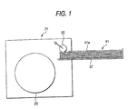

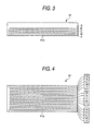
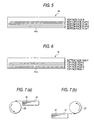


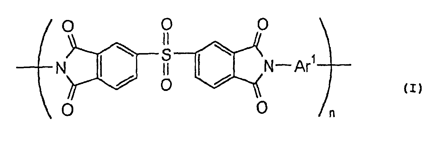
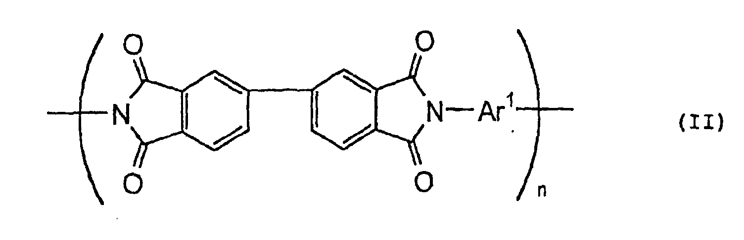
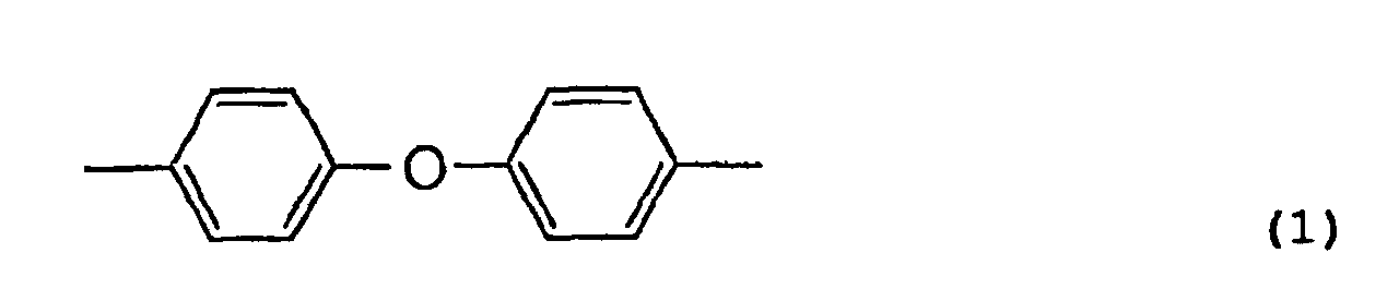


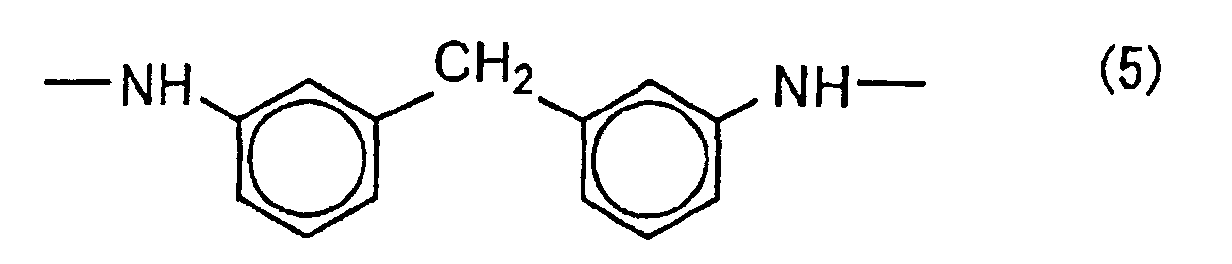

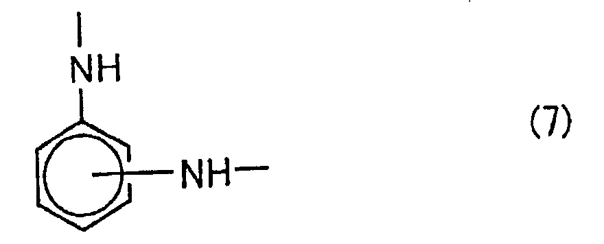
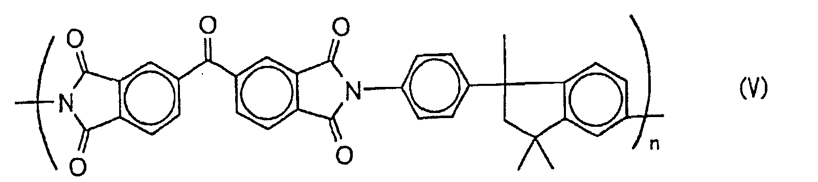


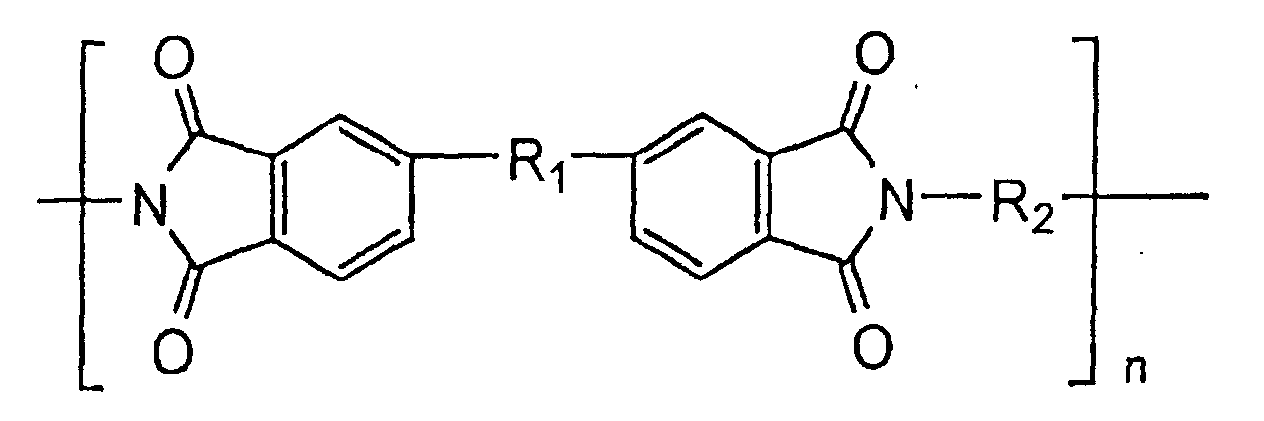 or
or


