EP1391307A2 - Method of filling ink supply bag for ink cartridge - Google Patents
Method of filling ink supply bag for ink cartridge Download PDFInfo
- Publication number
- EP1391307A2 EP1391307A2 EP03077497A EP03077497A EP1391307A2 EP 1391307 A2 EP1391307 A2 EP 1391307A2 EP 03077497 A EP03077497 A EP 03077497A EP 03077497 A EP03077497 A EP 03077497A EP 1391307 A2 EP1391307 A2 EP 1391307A2
- Authority
- EP
- European Patent Office
- Prior art keywords
- bag
- ink
- liquid ink
- full volume
- liquid
- Prior art date
- Legal status (The legal status is an assumption and is not a legal conclusion. Google has not performed a legal analysis and makes no representation as to the accuracy of the status listed.)
- Withdrawn
Links
Images







Classifications
-
- B—PERFORMING OPERATIONS; TRANSPORTING
- B65—CONVEYING; PACKING; STORING; HANDLING THIN OR FILAMENTARY MATERIAL
- B65B—MACHINES, APPARATUS OR DEVICES FOR, OR METHODS OF, PACKAGING ARTICLES OR MATERIALS; UNPACKING
- B65B3/00—Packaging plastic material, semiliquids, liquids or mixed solids and liquids, in individual containers or receptacles, e.g. bags, sacks, boxes, cartons, cans, or jars
- B65B3/22—Defoaming liquids in connection with filling
-
- B—PERFORMING OPERATIONS; TRANSPORTING
- B41—PRINTING; LINING MACHINES; TYPEWRITERS; STAMPS
- B41J—TYPEWRITERS; SELECTIVE PRINTING MECHANISMS, i.e. MECHANISMS PRINTING OTHERWISE THAN FROM A FORME; CORRECTION OF TYPOGRAPHICAL ERRORS
- B41J2/00—Typewriters or selective printing mechanisms characterised by the printing or marking process for which they are designed
- B41J2/005—Typewriters or selective printing mechanisms characterised by the printing or marking process for which they are designed characterised by bringing liquid or particles selectively into contact with a printing material
- B41J2/01—Ink jet
- B41J2/17—Ink jet characterised by ink handling
- B41J2/175—Ink supply systems ; Circuit parts therefor
- B41J2/17503—Ink cartridges
- B41J2/17506—Refilling of the cartridge
-
- B—PERFORMING OPERATIONS; TRANSPORTING
- B41—PRINTING; LINING MACHINES; TYPEWRITERS; STAMPS
- B41J—TYPEWRITERS; SELECTIVE PRINTING MECHANISMS, i.e. MECHANISMS PRINTING OTHERWISE THAN FROM A FORME; CORRECTION OF TYPOGRAPHICAL ERRORS
- B41J2/00—Typewriters or selective printing mechanisms characterised by the printing or marking process for which they are designed
- B41J2/005—Typewriters or selective printing mechanisms characterised by the printing or marking process for which they are designed characterised by bringing liquid or particles selectively into contact with a printing material
- B41J2/01—Ink jet
- B41J2/17—Ink jet characterised by ink handling
- B41J2/175—Ink supply systems ; Circuit parts therefor
- B41J2/17503—Ink cartridges
- B41J2/17513—Inner structure
-
- B—PERFORMING OPERATIONS; TRANSPORTING
- B41—PRINTING; LINING MACHINES; TYPEWRITERS; STAMPS
- B41J—TYPEWRITERS; SELECTIVE PRINTING MECHANISMS, i.e. MECHANISMS PRINTING OTHERWISE THAN FROM A FORME; CORRECTION OF TYPOGRAPHICAL ERRORS
- B41J2/00—Typewriters or selective printing mechanisms characterised by the printing or marking process for which they are designed
- B41J2/005—Typewriters or selective printing mechanisms characterised by the printing or marking process for which they are designed characterised by bringing liquid or particles selectively into contact with a printing material
- B41J2/01—Ink jet
- B41J2/17—Ink jet characterised by ink handling
- B41J2/175—Ink supply systems ; Circuit parts therefor
- B41J2/17503—Ink cartridges
- B41J2/17553—Outer structure
-
- B—PERFORMING OPERATIONS; TRANSPORTING
- B41—PRINTING; LINING MACHINES; TYPEWRITERS; STAMPS
- B41J—TYPEWRITERS; SELECTIVE PRINTING MECHANISMS, i.e. MECHANISMS PRINTING OTHERWISE THAN FROM A FORME; CORRECTION OF TYPOGRAPHICAL ERRORS
- B41J2/00—Typewriters or selective printing mechanisms characterised by the printing or marking process for which they are designed
- B41J2/005—Typewriters or selective printing mechanisms characterised by the printing or marking process for which they are designed characterised by bringing liquid or particles selectively into contact with a printing material
- B41J2/01—Ink jet
- B41J2/17—Ink jet characterised by ink handling
- B41J2/175—Ink supply systems ; Circuit parts therefor
- B41J2/17503—Ink cartridges
- B41J2/17559—Cartridge manufacturing
-
- B—PERFORMING OPERATIONS; TRANSPORTING
- B41—PRINTING; LINING MACHINES; TYPEWRITERS; STAMPS
- B41J—TYPEWRITERS; SELECTIVE PRINTING MECHANISMS, i.e. MECHANISMS PRINTING OTHERWISE THAN FROM A FORME; CORRECTION OF TYPOGRAPHICAL ERRORS
- B41J2/00—Typewriters or selective printing mechanisms characterised by the printing or marking process for which they are designed
- B41J2/005—Typewriters or selective printing mechanisms characterised by the printing or marking process for which they are designed characterised by bringing liquid or particles selectively into contact with a printing material
- B41J2/01—Ink jet
- B41J2/17—Ink jet characterised by ink handling
- B41J2/19—Ink jet characterised by ink handling for removing air bubbles
Definitions
- the invention relates generally to ink cartridges such as for ink jet printers, and in particular to a method of filling an ink supply bag to be included in an ink cartridge.
- a method of filling an ink supply bag with a liquid ink comprises:
- the method comprises:
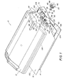
- FIGURES 1-22 show an alternative ink/cleaner cartridge 10 for an ink jet printer (not shown).
- the cartridge 10 when used as an ink cartridge includes the following components:
- the fitting 18 is attached via a thermal seal to the bag 16, within an elongate opening 26 in the bag.
- a small amount of melted material from the bag flows to between parallel ribs 28 along opposite longitudinal sides of the fitting 18 to provide an essentially leak-proof seal between the bag and the fitting.
- a rubber septum 30 is tightly inserted into an ink egress opening 32 in the snout 20 to plug the opening.
- an aluminum or stainless steel cap 34 is press-fitted on the snout 20.
- the cap 34 partially overlaps the septum 30 to capture the septum, and has a center opening 36 which allows a hollow needle (not shown) to pierce the septum in order to discharge an ink supply from the bag 16 when the cartridge 10 is used in an ink jet printer.
- the snout 20 has eight identical outer peripheral surfaces (sides) or facets 38 that project perpendicular from a longitudinal planar face 40 of the fitting 18 to form an octagon. See FIGURES 2 and 3.
- the collar 22 has a center opening 42 that is circumscribed by eight identical inner peripheral surfaces (sides) or facets 44 that form an octagon. This mutual or complementary configuration allows the snout 20 to be received in the center opening 42 only when the collar 22 is in any one of eight allowable angular orientations 0° or 360°, 45°, 90°, 135°, 180°, 225°, 270°, and 315°.
- the eight surfaces 44 of the collar 22 are aligned with the eight surfaces 38 of the snout 20 to position the collar relative to the snout in a selected one of the eight orientations. Then, the collar 22 is mated with the snout 20 in the selected orientation. Respective contact between the eight surfaces 38 and the eight surfaces 44 prevents the collar 22 from being rotated about the snout 22 and thus serves to fix the collar in the selected orientation.
- the selected orientation provides a visible indication that serves to identify the ink supply in the bag 16 such as by color or type.
- the collar 22 has a key slot or keyway 46 that is angular positioned in accordance with the selected orientation of the collar.
- the particular orientation of the key assembly must match the selected orientation of the collar 22 in order for the key tab to be received in the key slot 46.
- the number of the surfaces 38 of the snout 20 and the number of the surfaces 44 of the collar 22, need not each be eight (although they must be the same number). Preferably, the number of the surfaces 38 of the snout 20 and the number of the surfaces 44 of the collar 22 fall within the range 4-12. All that is necessary is that the number of the surfaces 38 of the snout 20 and the number of the surfaces 44 of the collar 22 form similar complementary polygons that permit the collar 22 to mate with the snout 20.
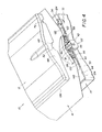
- the housing halves 12 and 14 at respective bottom wall portions 48 and 50 have opening halves 52 and 54 that form a single bottom opening when the housing halves are connected together. See FIGURES 1 and 4.
- the fitting 18 has a pair of L-shaped engageable-disenageable members or tabs 56 and 58 that project from respective areas of the face 40 (of the fitting) which are spaced from the snout 20.
- a pair of L-shaped engageable-disengageable members or tabs 60 and 62 project from an inner side 64 of the wall portion 50 and are spaced from the opening half 52.
- the L-shaped engageable-disengageable members 56 and 58 extend in opposite directions as do the L-shaped engageable-disengageable members 60 and 62.
- the bag 16 When the bag 16 is emptied, it is possible to remove the bag (with the fitting 18) from the cartridge 10. If the housing half 12 is disconnected from the housing half 14, the L-shaped engageable-disengageable members 56 and 58 are disengaged from the L-shaped engageable-disengageable members 60 and 62. Also, the collar 22 can be removed from the snout 20.
- L-shaped engageable-disengageable members can be provided on the fitting 18 and the housing half 14 in addition to the L-shaped engageable-disengageable members 56 and 58 and the L-shaped engageable-disengageable members 60 and 62. Also, it is not necessary that these engageable-disengageable members be L-shaped. A number of known engagements or interlocks can be used instead, such as pins in holes, etc.
- the housing halves 12 and 14 at bottom wall portions 48 and 50 have respective pocket portions 70 and 72 which include slightly smaller and larger wall opening portions 74 and 76 and sleeve or channel portions 78 and 80.
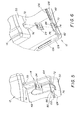
- the bottom wall portion 48 at an inner side 82 and the bottom wall portion 50 at the inner side 64 have respective ink blocking shield segments 84 and 86 that project inwardly of the housing halves 12 and 14 from the inner sides. See FIGURES 5 and 6.
- the ink blocking shield segment 84 is an integral extension of the inner side 82 and extends across the wall opening portion 74
- the ink blocking shield segment 86 is an integral extension of the inner side 64 and extends across the wall opening portion 76. This is to isolate or seal the wall opening portions 74 and 76 from the interiors of the housing halves 12 and 14.
- the wall opening portions 74 and 76 are necessary to permit electrical contact to be made with the memory chip 24 when the cartridge 10 is used in an ink jet printer.
- the memory chip 24 is peripheral-edge supported in the channel portions 78 and 80 to hold the memory chip in the wall opening portions 74 and 76.
- the pocket portions 70 and 72 combine to form a single pocket including the wall opening portions 74 and 76 combining to form a single wall opening, and the ink blocking shield segments 84 and 86 abut end-to-end to seal the single wall opening.
- the ink supply bag 16, which is between the housing halves 12 and 14, might per chance leak ink.
- the ink blocking shield segments 84 and 86 which are then abutted end-to-end prevent any ink from entering the wall opening portions 74 and 76 and contaminating the memory chip 24.
- the housing half 12 has at least two interior stakes 88 and 90 that project from the housing half and are parallel to the bottom wall portion 48 of the housing half.
- respective tips 92 and 94 of the stakes 88 and 90 are melted preferably onto the L-shaped engageable-disengageable members 56 and 58 of the fitting 18 to adhere the stakes to those L-shaped members.
- the stakes 88 and 90 thus hold the L-shaped engageable-disengageable members 56 and 58 of the fitting 18 fast to the housing half 12, and can be separated from those L-shaped members only by breaking the connection at the melted tips 92 and 94 (or by breaking the stakes and/or the L-shaped members).
- the tips 92 and 94 of the stakes 88 and 90 can be melted onto the L-shaped engageable members 60 and 62 of the housing half 14 to hold those L-shaped members fast to the housing half 12.
- the tips 92 and 94 of the stakes 88 and 90 can be melted onto both the L-shaped engageable members 56 and 58 of the fitting 18 and the L-shaped engageable members 60 and 62 of the housing half 14.
- the tips 92 and 94 of the stakes 88 and 90 can be melted onto the L-shaped engageable members 56 and 58 of the fitting 18 and/or the L-shaped engageable members 60 and 62 of the housing half 14 via a conventional vibration weld that melts the tips.
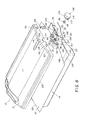
- FIGURES 8-12 show the cartridge 10 when used as a cleaner cartridge instead of an ink cartridge.
- the bag 16 is a cleaner supply bag instead of an ink supply bag, and a cap 96 is mated with the snout 20 in place of the collar 22.
- the cap 96 must be removed from the snout 20 to allow a hollow needle (not shown) to pierce the septum 30 in order to discharge a cleaner material, e.g. a known cleaner solution, from the bag 16.
- the cleaner material is intended to be applied in an ink jet printer instead of an ink supply, to clean the ink jet printer of any ink residue.
- the cap 96 has the same diameter as the collar 22 and, like the center opening 42 in the collar, it has a center opening 98 for receiving the snout 20. See FIGURES 3 and 10. Also, like the outer peripheral groove 66 in the collar 22, the cap 96 has an outer peripheral groove 100 for receiving the edge 65 of the opening half 54 in the bottom wall portion 50 of the housing half 14 and for receiving the edge 68 of the opening half 52 in the bottom wall portion 48 of the housing half 12. See FIGURES 1,4 and 8,11.
- the bottom wall portion 48 of the housing half 12 has a pair of clearance recesses 102 and 104 at the edge 68 of the opening half 52
- the bottom wall portion 50 of the housing half 14 has a pair of clearance recesses 106 and 108 at the edge 65 of the opening half 54.
- the four clearance recesses 102, 104, 106 and 108 permit a pair of lugs 110 and 112 on the cap 96 to be admitted through the opening halves 52 and 54. Then, when the cap 96 is rotated on the snout 20, the lugs 110 and 112 engage with the bottom wall portions 48 and 50 at their inner sides 82 and 64.
- the inner side 82 of the bottom wall portion 48 has a cavity 114 adjacent the edge 68 of the opening half 52
- the inner side 64 of the bottom wall portion 50 has a cavity 116 adjacent the edge 65 of the opening half 54.
- the cavities 114 and 116 receive respective protuberances or bumps 118 and 120 adjacent the lugs 110 and 112 on the cap 96 when the cap is rotated on the snout 20 (with the lugs against the inner sides 82 and 64 of the bottom wall portions 48 and 50).
- the protuberances 118 and 120 in combination with the cavities 114 and 116 serve to prevent unintended rotation of the cap 96.
- a number of identical protuberances or tabs 122 project from an edge 124 along the housing half 14 and are to be received in respective cavities 126 in an edge 128 along the housing half 12.
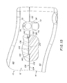
- the protuberances 122 each have an original length 130 in FIGURE 15, preferably about 1.38 mm, that is about 0.38 mm greater than the depth of each cavity 126 (the depth of each cavity is about 1.00 mm). Consequently, when the protuberances 122 are received in the cavities 126, the edges 124 and 128 of the housing halves 14 and 12 are separated by a space or gap 132 in FIGURE 15 which is about 0.38 mm. This prevents the edges 124 and 128 from abutting to form a seam 134 between the housing halves 14 and 12.
- the protuberances 122 are welded at their tips 136 (within the cavities 126) to the housing half 12, preferably by a known vibration welding process, as shown in FIGURE 14.
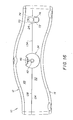
- the heat generated by the welding melts the tips 136 to reduce the length 130 of the protuberances 122 from about 1.38 mm to about 1.00 mm, i.e. about 0.38 mm. This eliminates the spaces 132, which permits the edges 124 and 128 to abut to form the seam 134 between the housing halves 14 and 12. See FIGURES 14 and 16.
- each protuberance 122 has a width 138, preferably about 16.98 mm. Clearances spaces 140 of at least 0.33 mm exist between each side of a protuberance 122 and respective sides of a cavity 126. Thus, the width of a cavity 126 is at least 17.31 mm.
- a flash 142 is formed at respective welds 144 between the tips and the housing half 12.
- the flash 142 spreads from each weld 144 into the clearances spaces 140.
- the flash 142 only partially fills the clearance spaces 140.
- the protuberance 122 and the cavities 126 are mutually dimensioned to restrict the flash 142 substantially to within the cavities. This prevents the flash 142 from spreading between the edges 124 and 128 of the housing halves 14 and 12, since if the flash was to spread between the edges it could interfere with their abutting to form the seam 134.
- the flash 142 prevents the flash 142 from bulging outward from the seam 134 including in the vicinity of the wall opening portions 74 and 76 (that combine to form a single wall opening for permitting electrical contact to be made with the memory chip 24), since if the flash was to bulge outward of the seam in the vicinity of the wall opening portions it might present an obstacle to making electrical contact with the memory chip.
- a method of filling the bag 16 with the ink supply, preferably a known liquid ink 146, is as follows.
- the bag 16 is positioned vertically or erect with a bottom end 148 down and a top end 150 up.
- An intake/exhaust port 152 that is attached to the bag 16 at the top end 150 faces upward.
- the fitting 18 that is attached to the bag 16, including the snout 20 with the septum 30 and the cap 34, faces downward.
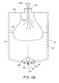
- an air delivery nozzle 154 is inserted at least into the port 152, preferably through the port and into the bag 16 as shown. Then, air under pressure is flowed from an end orifice 156 in the air delivery nozzle 154 to expand the bag 16 substantially to its full volume.
- the air delivery nozzle 154 is replaced in the port 152 with a liquid delivery nozzle 158.
- the liquid delivery nozzle 158 is inserted through the port 152 and into the bag 16 to position an end orifice 160 in that nozzle deep inside the bag as shown.
- the liquid ink 146 is flowed from the end orifice 160 in the liquid delivery nozzle 158 to fill the bag 16 up to a fill line 162.
- the fill line 162 is at 60%-75%, preferably 65%, of the full volume of the bag 16 in order to fill the bag to less than its capacity.
- the filling is done by flowing the liquid ink 146 from the end orifice 160 at an initial delivery velocity that is low enough to substantially prevent bubbles from forming in the delivered liquid in the bag 16.
- the delivery velocity is increased to speed up the fill rate for the bag. This is done only until the bag 16 is filled to the predetermined percentage of its full volume.
- the bag 16 can be filled with the liquid ink 146 to the predetermined percentage of its full volume in a vacuum environment so that air need not be forced into the bag to expand the bag substantially to its full volume before the bag is filled as in FIGURE 18.
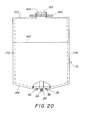
- the liquid delivery nozzle 158 is removed from the port 152, and any residual air that may be in the bag 16 is expelled through the port by squeezing the bag to raise the liquid level 164 in the bag at least into the port. (This need not be done if the bag 16 is filled with the liquid ink 146 to the predetermined percentage of its full volume in a vacuum environment.) Then, the bag 16, which is now partially collapsed to conform substantially to the volume of the liquid ink 146 in the bag, is sealed at or near the port 152, preferably using a known heat-clamp 166 to heat seal the port, and then using a cold-clamp (not shown) to uniformly cool the port.
- the bag 16 is larger than the cartridge housing 12, 14 as can be seen in FIGURE 1. Specifically, as depicted in FIGURE 17, the bag 16 has a width 168 that is greater than a width of the cartridge housing 12, 14 and has a length 170 that is less than a length of the cartridge housing. This allows the bag 16 to be folded widthwise to fit in the cartridge housing 12, 14.
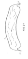
- the bag 146 When the bag 146 is filled with the liquid ink 146 to the predetermined percentage of its full volume, and is partially collapsed to conform substantially to the volume of the liquid ink 146 in the bag and sealed at or near the port 152, it is then folded widthwise as shown in FIGURE 21 and placed in the housing half 14.
- the bag 146 can substantially fit in the cartridge housing 12, 14 when the housing halves 12 and 14 are connected together. See FIGURE 22.
- the bag 16 is folded widthwise along two opposite longitudinal edge portions 172 and 174 from a longitudinal center portion 176 between the longitudinal edge portions. See FIGURES 17 and 21.
- the longitudinal edge portions 172 and 174 are each folded about 85°-95°, preferably 90° as shown in FIGURE 21.
- the longitudinal edge portions 172 and 174 each have a width 178 that is about 2%-5%, preferably 3%, of the width 168 of the bag 16.
- the longitudinal center portion 176 has a width 180 that is about 97% of the width 168 of the bag 16.
- the bag 16 as folded has been filled with the liquid ink 146 to only a predetermined percentage of its full volume, the bag should not rupture if the cartridge housing 12, 14 is mechanically shocked, such as by dropping the cartridge housing onto a hard surface.
Landscapes
- Engineering & Computer Science (AREA)
- Manufacturing & Machinery (AREA)
- Mechanical Engineering (AREA)
- Ink Jet (AREA)
Abstract
Description
- FIGURE 1 is an exploded perspective view of an ink cartridge including a pair of housing halves, a fitting including an egress snout for discharging an ink supply from a bag or alternatively for discharging a cleaner supply from the bag, and a collar that mates with the snout in any one of a number of allowable orientations to provide an identification of the ink supply;
- FIGURES 2 and 3 are exploded perspective views of the egress snout and the collar as shown from opposite views;
- FIGURE 4 is a perspective view similar to FIGURE 1, except that the cartridge is shown partially assembled;
- FIGURES 5 and 6 are exploded perspective views of a memory chip shown being inserted into a pocket in the housing halves;
- FIGURE 7 is a perspective view similar to FIG. 4, except that one of the housing halves is shown partially cut away to reveal stakes that are adhered to the fitting;
- FIGURE 8 is a perspective view similar to FIGURE 1, except that a cap is mated with the snout in place of the collar when the cleaner supply rather than the ink supply is stored in the bag;
- FIGURES 9, 10 and 11 are perspective views similar to FIGURES 2, 3 and 4, except that the cap is shown rather than the collar;
- FIGURE 12 is a perspective view similar to FIGURE 11, but as shown from an opposite view;
- FIGURE 13 is a section view of the housing halves, showing how protuberances on one of the housing halves are received within respective cavities in the other housing half in order to be welded to the other housing half;
- FIGURE 14 is a section view of the housing halves, showing a protuberance welded to the other housing half;
- FIGURE 15 is a section view similar to FIGURE 13, showing arrows to indicate various dimensions;
- FIGURE 16 is an end view of the housing halves connected together;
- FIGURE 17 is a plan view of the bag when empty and shown bottom end down and top end up;
- FIGURE 18 is a plan view similar to FIGURE 17, showing an air delivery nozzle blowing air into the bag to expand the bag substantially to its full volume;
- FIGURE 19 is a plan view similar to FIGURE 17, showing a liquid delivery nozzle filling the bag with a liquid ink;
- FIGURE 20 is a plan view similar to FIGURE 17, showing the bag filled to 65% of its capacity (its full volume) and being sealed;
- FIGURE 21 is a section view of the bag collapsed to 65% of its capacity and folded about 90° at opposite longitudinal edge portions; and
- FIGURE 22 is a section view of the housing halves connected together and containing the bag as shown in FIGURE 21.
Claims (9)
- A method of filling an ink supply bag with a liquid ink, comprising:flowing the liquid ink from an orifice in a nozzle extending deep into the bag and at an initial delivery velocity that is low enough to substantially prevent bubbles from forming in the delivered liquid in the bag in order to prevent the liquid ink from foaming, and after the liquid level in the bag rises to immerse at least the orifice increasing the delivery velocity to speed up the fill rate for the bag.
- A method as recited in claim 1, wherein the bag is filled with the liquid ink only to a predetermined percentage of its full volume to fill the bag to less than its capacity.
- A method as recited in claim 2, wherein the bag is filled with the liquid ink to about 60%-75% of its full volume.
- A method as recited in claim 2, wherein the bag is filled with the liquid ink to about 65% of its full volume.
- A method as recited in claim 2, wherein the bag is collapsed substantially to the volume of the liquid ink in the bag after the bag is filled with the liquid ink to the predetermined percentage of its full volume.
- A method as recited in claim 2, wherein air is forced into the bag to expand the bag substantially to its full volume before the bag is filled with the liquid ink to the predetermined percentage of its full volume.
- A method as recited in claim 2, wherein the bag is filled with the liquid ink to the predetermined percentage of its full volume in a vacuum environment so that air need not be forced into the bag to expand the bag substantially to its full volume before the bag is filled.
- A method as recited in claim 2, wherein the nozzle is removed from the bag after the bag is filled with the liquid ink to the predetermined percentage of its full volume, then the bag is squeezed to raise the liquid level in the bag to expel air from the bag, and finally the bag is sealed.
- A method of filling an ink supply bag with a liquid ink, comprising:positioning the bag bottom end down and top end up, with a snout that is attached to the bottom end and has an ink egress opening plugged by a septum facing downward, and with an intake/exhaust port that is attached to the top end facing upward;flowing air through the intake/exhaust port into the bag to expand the bag substantially to its full volume;flowing the liquid ink through the intake/exhaust port into the bag and filling the bag with the liquid ink to a predetermined percentage of its full volume to fill the bag to less than its capacity;expelling air that may be in the bag through the intake/exhaust port; andsealing the bag at or near the intake/exhaust port.
Applications Claiming Priority (2)
| Application Number | Priority Date | Filing Date | Title |
|---|---|---|---|
| US10/224,805 US6837576B2 (en) | 2002-08-21 | 2002-08-21 | Method of filling ink supply bag for ink cartridge |
| US224805 | 2002-08-21 |
Publications (2)
| Publication Number | Publication Date |
|---|---|
| EP1391307A2 true EP1391307A2 (en) | 2004-02-25 |
| EP1391307A3 EP1391307A3 (en) | 2004-04-07 |
Family
ID=31187978
Family Applications (1)
| Application Number | Title | Priority Date | Filing Date |
|---|---|---|---|
| EP03077497A Withdrawn EP1391307A3 (en) | 2002-08-21 | 2003-08-11 | Method of filling ink supply bag for ink cartridge |
Country Status (2)
| Country | Link |
|---|---|
| US (1) | US6837576B2 (en) |
| EP (1) | EP1391307A3 (en) |
Cited By (2)
| Publication number | Priority date | Publication date | Assignee | Title |
|---|---|---|---|---|
| WO2006093472A1 (en) * | 2005-03-03 | 2006-09-08 | Inke Pte Ltd | Ink reservoir |
| US10047769B2 (en) | 2014-04-29 | 2018-08-14 | Volvo Construction Equipment Ab | Flow control valve for construction equipment |
Families Citing this family (9)
| Publication number | Priority date | Publication date | Assignee | Title |
|---|---|---|---|---|
| US7441865B2 (en) * | 2004-01-21 | 2008-10-28 | Silverbrook Research Pty Ltd | Printhead chip having longitudinal ink supply channels |
| US7367650B2 (en) * | 2004-01-21 | 2008-05-06 | Silverbrook Research Pty Ltd | Printhead chip having low aspect ratio ink supply channels |
| JP4078387B1 (en) * | 2007-06-29 | 2008-04-23 | ワールドネットワーク株式会社 | Ink tank and ink cartridge |
| US7611235B2 (en) * | 2007-08-17 | 2009-11-03 | Thomas Richards | Method and device to prevent refill of cartridge |
| US8544994B2 (en) * | 2010-12-28 | 2013-10-01 | Brother Kogyo Kabushiki Kaisha | Ink cartridge |
| JP6163991B2 (en) * | 2013-09-17 | 2017-07-19 | セイコーエプソン株式会社 | Liquid container and liquid container |
| JP7119683B2 (en) * | 2018-07-17 | 2022-08-17 | セイコーエプソン株式会社 | liquid injector |
| EP3844001B1 (en) | 2019-11-08 | 2023-04-12 | Hewlett-Packard Development Company, L.P. | Print liquid supplies for printing devices |
| TWI771993B (en) * | 2021-04-22 | 2022-07-21 | 唐國忠 | Multilayer telescopic air bag extrusion air pneumatic pail |
Family Cites Families (64)
| Publication number | Priority date | Publication date | Assignee | Title |
|---|---|---|---|---|
| US4183031A (en) | 1976-06-07 | 1980-01-08 | Silonics, Inc. | Ink supply system |
| US4506276A (en) | 1977-06-16 | 1985-03-19 | System Industries, Inc. | Ink supply system |
| AU2597984A (en) | 1983-03-29 | 1984-10-04 | Technosearch Pty. Limited | Filling liner bags with liquid |
| JPS59214656A (en) | 1983-05-19 | 1984-12-04 | Sanyo Electric Co Ltd | Ink jet printer |
| US4491433A (en) | 1983-08-29 | 1985-01-01 | Centronics Data Computer Corp. | Venting and ink recycling device |
| DE3405164A1 (en) | 1984-02-14 | 1985-08-22 | Olympia Werke Ag, 2940 Wilhelmshaven | Ink supply container for ink jet printers |
| JPH0825279B2 (en) | 1986-06-25 | 1996-03-13 | キヤノン株式会社 | Ink supply device |
| US4853708A (en) | 1988-03-03 | 1989-08-01 | Eastman Kodak Company | Ink cartridge and housing construction for multicolor ink jet printing apparatus |
| US4907019A (en) | 1989-03-27 | 1990-03-06 | Tektronix, Inc. | Ink jet cartridges and ink cartridge mounting system |
| US4961088A (en) | 1989-04-20 | 1990-10-02 | Xerox Corporation | Monitor/warranty system for electrostatographic reproducing machines using replaceable cartridges |
| DE69034212T2 (en) | 1989-08-05 | 2006-07-13 | Canon K.K. | Ink jet recording device and ink cartridge therefor |
| JP3222454B2 (en) | 1990-02-02 | 2001-10-29 | キヤノン株式会社 | Ink tank cartridge |
| USD341157S (en) | 1990-12-10 | 1993-11-09 | Seiko Epson Corporation | Ink bag for printer |
| EP0715958B1 (en) | 1991-05-27 | 1998-08-12 | Seiko Epson Corporation | Ink cartridge for ink jet recording apparatus |
| US5745137A (en) | 1992-08-12 | 1998-04-28 | Hewlett-Packard Company | Continuous refill of spring bag reservoir in an ink-jet swath printer/plotter |
| AU1812392A (en) | 1991-07-12 | 1993-01-14 | Minnesota Mining And Manufacturing Company | Bottle keying system |
| US5410641A (en) | 1991-10-23 | 1995-04-25 | Seiko Epson Corporation | Intelligent cartridge for attachment to a printer to perform image processing tasks in a combination image processing system and method of image processing |
| US6003985A (en) | 1991-12-11 | 1999-12-21 | Canon Kabushiki Kaisha | Ink jet recording apparatus |
| US5406320A (en) | 1992-03-10 | 1995-04-11 | Scitex Digital Printing, Inc. | Ink replenishment assemblies for ink jet printers |
| GB9205870D0 (en) | 1992-03-18 | 1992-04-29 | Willett Int Ltd | Replenishment of reservoirs |
| US5266968A (en) | 1992-03-27 | 1993-11-30 | Eastman Kodak Company | Non-volatile memory thermal printer cartridge |
| JP2962044B2 (en) | 1992-05-29 | 1999-10-12 | 富士ゼロックス株式会社 | Ink tank, inkjet cartridge, and inkjet recording device |
| US5561450A (en) | 1992-09-30 | 1996-10-01 | Pitney Bowes Inc. | Apparatus for mounting an ink jet cartridge on a support therefor |
| US6000791A (en) | 1992-12-23 | 1999-12-14 | Hewlett-Packard Company | Printer having a removable print cartridge with handle incorporating an ink inlet value |
| EP0609863B1 (en) | 1993-02-02 | 1998-05-13 | Seiko Epson Corporation | Ink-jet recording apparatus |
| US5408746A (en) | 1993-04-30 | 1995-04-25 | Hewlett-Packard Company | Datum formation for improved alignment of multiple nozzle members in a printer |
| US5519422A (en) | 1993-05-03 | 1996-05-21 | Hewlett-Packard Company | Method and device for preventing unintended use of print cartridges |
| DE69424724T2 (en) | 1993-08-31 | 2000-11-23 | Canon K.K., Tokio/Tokyo | Method and device for filling ink cartridges with ink |
| US5619239A (en) | 1993-11-29 | 1997-04-08 | Canon Kabushiki Kaisha | Replaceable ink tank |
| JP3492441B2 (en) | 1994-03-15 | 2004-02-03 | ゼロックス・コーポレーション | Thermal inkjet printbar valve connector and ink handling system |
| WO1996005061A1 (en) | 1994-08-09 | 1996-02-22 | Encad, Inc. | Printer ink cartridge |
| US5610635A (en) | 1994-08-09 | 1997-03-11 | Encad, Inc. | Printer ink cartridge with memory storage capacity |
| US5825387A (en) | 1995-04-27 | 1998-10-20 | Hewlett-Packard Company | Ink supply for an ink-jet printer |
| US6203147B1 (en) | 1994-12-22 | 2001-03-20 | Hewlett-Packard Company | Electrical and fluidic interface for an ink supply |
| US5956057A (en) | 1996-08-30 | 1999-09-21 | Hewlett-Packard Company | Ink container having electronic and mechanical features enabling plug compatibility between multiple supply sizes |
| US5699091A (en) | 1994-12-22 | 1997-12-16 | Hewlett-Packard Company | Replaceable part with integral memory for usage, calibration and other data |
| US5825388A (en) | 1994-12-27 | 1998-10-20 | Brother Kogyo Kabushiki Kaisha | Ink jetting apparatus |
| US5530531A (en) | 1995-03-15 | 1996-06-25 | Hewlett-Packard Company | Multiple cartridge keying apparatus |
| US6183077B1 (en) | 1995-04-27 | 2001-02-06 | Hewlett-Packard Company | Method and apparatus for keying ink supply containers |
| US6130695A (en) | 1995-04-27 | 2000-10-10 | Hewlett-Packard Company | Ink delivery system adapter |
| US5721576A (en) | 1995-12-04 | 1998-02-24 | Hewlett-Packard Company | Refill kit and method for refilling an ink supply for an ink-jet printer |
| US5710579A (en) | 1995-05-04 | 1998-01-20 | Calcomp Inc. | Sensor system for printers |
| US5880764A (en) | 1995-12-04 | 1999-03-09 | Hewlett-Packard Company | Adaptive ink supply for an ink-jet printer |
| DE19549438C2 (en) | 1995-12-21 | 2000-11-02 | Pelikan Produktions Ag Egg | Liquid cartridge and printhead for an ink jet printer |
| US5751322A (en) | 1996-02-13 | 1998-05-12 | Hewlett-Packard Company | Limited access needle/septum ink-supply interface mechanism |
| US6164743A (en) | 1996-04-17 | 2000-12-26 | Hewlett-Packard Company | Ink container with an inductive ink level sense |
| US5959647A (en) | 1996-04-29 | 1999-09-28 | Hewlett-Packard Company | Technique for converting single cartridge monochrome printer to multi-cartridge color inkjet printer |
| JP3295339B2 (en) | 1996-08-30 | 2002-06-24 | キヤノン株式会社 | Ink tank, holder, inkjet cartridge and cap |
| JP3666537B2 (en) | 1996-11-14 | 2005-06-29 | セイコーエプソン株式会社 | Method for manufacturing ink cartridge for ink jet recording apparatus |
| US5860363A (en) | 1997-01-21 | 1999-01-19 | Hewlett-Packard Company | Ink jet cartridge with separately replaceable ink reservoir |
| US5788388A (en) | 1997-01-21 | 1998-08-04 | Hewlett-Packard Company | Ink jet cartridge with ink level detection |
| US6227638B1 (en) | 1997-01-21 | 2001-05-08 | Hewlett-Packard Company | Electrical refurbishment for ink delivery system |
| US6168262B1 (en) | 1997-01-30 | 2001-01-02 | Hewlett-Packard Company | Electrical interconnect for replaceable ink containers |
| US6227643B1 (en) | 1997-05-20 | 2001-05-08 | Encad, Inc. | Intelligent printer components and printing system |
| US6151039A (en) | 1997-06-04 | 2000-11-21 | Hewlett-Packard Company | Ink level estimation using drop count and ink level sense |
| US5949459A (en) | 1997-06-04 | 1999-09-07 | Hewlett-Packard Company | Method and apparatus for securing an ink container |
| US5969734A (en) * | 1997-08-13 | 1999-10-19 | Mitsubishi Pencil Corporation Of America | Method and apparatus for refilling an ink cartridge |
| US6199973B1 (en) | 1997-09-03 | 2001-03-13 | Hewlett Packard Company | Storage container for inkjet cartridges having removable capping means and a method for storing inkjet cartridges |
| US6019449A (en) | 1998-06-05 | 2000-02-01 | Hewlett-Packard Company | Apparatus controlled by data from consumable parts with incorporated memory devices |
| US6065826A (en) | 1998-10-06 | 2000-05-23 | Hewlett-Packard Company | Modular print cartridge receptacle for use in inkjet printing systems |
| US6331053B1 (en) * | 1999-01-29 | 2001-12-18 | Hewlett-Packard Company | Method and apparatus for pressurizing ink in an inkjet printer ink supply using spring force |
| US6155678A (en) | 1999-10-06 | 2000-12-05 | Lexmark International, Inc. | Replaceable ink cartridge for ink jet pen |
| US6227663B1 (en) | 2000-01-05 | 2001-05-08 | Hewlett-Packard Company | Ink-jet print cartridge having a low profile |
| US6199977B1 (en) | 2000-04-13 | 2001-03-13 | Lexmark International, Inc. | Cartridge body for ink jet printer |
-
2002
- 2002-08-21 US US10/224,805 patent/US6837576B2/en not_active Expired - Fee Related
-
2003
- 2003-08-11 EP EP03077497A patent/EP1391307A3/en not_active Withdrawn
Cited By (2)
| Publication number | Priority date | Publication date | Assignee | Title |
|---|---|---|---|---|
| WO2006093472A1 (en) * | 2005-03-03 | 2006-09-08 | Inke Pte Ltd | Ink reservoir |
| US10047769B2 (en) | 2014-04-29 | 2018-08-14 | Volvo Construction Equipment Ab | Flow control valve for construction equipment |
Also Published As
| Publication number | Publication date |
|---|---|
| US20040036747A1 (en) | 2004-02-26 |
| US6837576B2 (en) | 2005-01-04 |
| EP1391307A3 (en) | 2004-04-07 |
Similar Documents
| Publication | Publication Date | Title |
|---|---|---|
| US6705714B1 (en) | Ink cartridge having ink supply bag filled to less than capacity and folded in cartridge housing | |
| US6837576B2 (en) | Method of filling ink supply bag for ink cartridge | |
| CN100551705C (en) | ink cartridge | |
| CN104512119B (en) | The renovation process and liquid housing container of liquid container | |
| US20020122104A1 (en) | Liquid container, elastic member for liquid container, and recording apparatus | |
| CN101181845A (en) | Method of making liquid container | |
| US6830323B2 (en) | Restricting flash spread when welding housing halves of cartridge together | |
| CN111746902B (en) | Liquid storage bottle and method for manufacturing the same, and resin member and method for manufacturing the same | |
| KR20030028131A (en) | Ink cartridge | |
| US6773098B2 (en) | Method of filling ink supply bag for ink cartridge | |
| CN104512117B (en) | Liquid housing container recycling method, and liquid housing container | |
| JP3967287B2 (en) | ink cartridge | |
| US20040012660A1 (en) | Ink cartridge having connectable-disconnectable housing and ink supply bag | |
| JP2002370384A (en) | Liquid storage container and liquid ejection recording apparatus using the container | |
| US6709093B2 (en) | Ink cartridge in which ink supply bag held fast to housing | |
| US6712459B2 (en) | Ink cartridge having shielded pocket for memory chip | |
| US6715864B2 (en) | Disposable ink supply bag having connector-fitting | |
| US6755501B2 (en) | Alternative ink/cleaner cartridge | |
| JP3586206B2 (en) | Ink tank | |
| CN118927809B (en) | A jig and ink cartridge regeneration method | |
| CN120921823A (en) | Ink storage bag and method for manufacturing ink storage bag | |
| EP1382453A1 (en) | Ink cartridge having ink identifier oriented to provide ink identification | |
| JP2000301731A5 (en) | ||
| US6705713B2 (en) | Disposable ink assemblage | |
| KR101790653B1 (en) | Liquid pack and fabrication method the same, ink catridge and printer with the same |
Legal Events
| Date | Code | Title | Description |
|---|---|---|---|
| PUAI | Public reference made under article 153(3) epc to a published international application that has entered the european phase |
Free format text: ORIGINAL CODE: 0009012 |
|
| PUAL | Search report despatched |
Free format text: ORIGINAL CODE: 0009013 |
|
| AK | Designated contracting states |
Kind code of ref document: A2 Designated state(s): AT BE BG CH CY CZ DE DK EE ES FI FR GB GR HU IE IT LI LU MC NL PT RO SE SI SK TR |
|
| AX | Request for extension of the european patent |
Extension state: AL LT LV MK |
|
| AK | Designated contracting states |
Kind code of ref document: A3 Designated state(s): AT BE BG CH CY CZ DE DK EE ES FI FR GB GR HU IE IT LI LU MC NL PT RO SE SI SK TR |
|
| AX | Request for extension of the european patent |
Extension state: AL LT LV MK |
|
| AKX | Designation fees paid | ||
| REG | Reference to a national code |
Ref country code: DE Ref legal event code: 8566 |
|
| STAA | Information on the status of an ep patent application or granted ep patent |
Free format text: STATUS: THE APPLICATION IS DEEMED TO BE WITHDRAWN |
|
| 18D | Application deemed to be withdrawn |
Effective date: 20041008 |