EP1390649B1 - Method for the manufacture of a ball valve between two tubes - Google Patents
Method for the manufacture of a ball valve between two tubes Download PDFInfo
- Publication number
- EP1390649B1 EP1390649B1 EP02724354A EP02724354A EP1390649B1 EP 1390649 B1 EP1390649 B1 EP 1390649B1 EP 02724354 A EP02724354 A EP 02724354A EP 02724354 A EP02724354 A EP 02724354A EP 1390649 B1 EP1390649 B1 EP 1390649B1
- Authority
- EP
- European Patent Office
- Prior art keywords
- cover
- tubes
- tube
- valve
- mantle
- Prior art date
- Legal status (The legal status is an assumption and is not a legal conclusion. Google has not performed a legal analysis and makes no representation as to the accuracy of the status listed.)
- Expired - Lifetime
Links
- 238000000034 method Methods 0.000 title claims abstract description 19
- 238000004519 manufacturing process Methods 0.000 title claims abstract description 13
- 238000003466 welding Methods 0.000 claims abstract description 64
- 238000010894 electron beam technology Methods 0.000 claims abstract description 3
- 238000005304 joining Methods 0.000 claims description 13
- 239000000463 material Substances 0.000 claims description 12
- 230000013011 mating Effects 0.000 claims description 4
- 230000000149 penetrating effect Effects 0.000 claims description 3
- 230000005855 radiation Effects 0.000 description 5
- 230000006835 compression Effects 0.000 description 4
- 238000007906 compression Methods 0.000 description 4
- 230000007547 defect Effects 0.000 description 2
- 238000010438 heat treatment Methods 0.000 description 2
- 238000003754 machining Methods 0.000 description 2
- 239000000155 melt Substances 0.000 description 2
- 238000000465 moulding Methods 0.000 description 2
- 239000011324 bead Substances 0.000 description 1
- 230000007797 corrosion Effects 0.000 description 1
- 238000005260 corrosion Methods 0.000 description 1
- 230000000694 effects Effects 0.000 description 1
- 230000001788 irregular Effects 0.000 description 1
- 238000002844 melting Methods 0.000 description 1
- 230000008018 melting Effects 0.000 description 1
- 239000002184 metal Substances 0.000 description 1
Images

Classifications
-
- F—MECHANICAL ENGINEERING; LIGHTING; HEATING; WEAPONS; BLASTING
- F16—ENGINEERING ELEMENTS AND UNITS; GENERAL MEASURES FOR PRODUCING AND MAINTAINING EFFECTIVE FUNCTIONING OF MACHINES OR INSTALLATIONS; THERMAL INSULATION IN GENERAL
- F16K—VALVES; TAPS; COCKS; ACTUATING-FLOATS; DEVICES FOR VENTING OR AERATING
- F16K27/00—Construction of housing; Use of materials therefor
- F16K27/06—Construction of housing; Use of materials therefor of taps or cocks
- F16K27/067—Construction of housing; Use of materials therefor of taps or cocks with spherical plugs
-
- F—MECHANICAL ENGINEERING; LIGHTING; HEATING; WEAPONS; BLASTING
- F16—ENGINEERING ELEMENTS AND UNITS; GENERAL MEASURES FOR PRODUCING AND MAINTAINING EFFECTIVE FUNCTIONING OF MACHINES OR INSTALLATIONS; THERMAL INSULATION IN GENERAL
- F16K—VALVES; TAPS; COCKS; ACTUATING-FLOATS; DEVICES FOR VENTING OR AERATING
- F16K5/00—Plug valves; Taps or cocks comprising only cut-off apparatus having at least one of the sealing faces shaped as a more or less complete surface of a solid of revolution, the opening and closing movement being predominantly rotary
- F16K5/06—Plug valves; Taps or cocks comprising only cut-off apparatus having at least one of the sealing faces shaped as a more or less complete surface of a solid of revolution, the opening and closing movement being predominantly rotary with plugs having spherical surfaces; Packings therefor
- F16K5/0621—Plug valves; Taps or cocks comprising only cut-off apparatus having at least one of the sealing faces shaped as a more or less complete surface of a solid of revolution, the opening and closing movement being predominantly rotary with plugs having spherical surfaces; Packings therefor with a spherical segment mounted around a supply pipe
-
- Y—GENERAL TAGGING OF NEW TECHNOLOGICAL DEVELOPMENTS; GENERAL TAGGING OF CROSS-SECTIONAL TECHNOLOGIES SPANNING OVER SEVERAL SECTIONS OF THE IPC; TECHNICAL SUBJECTS COVERED BY FORMER USPC CROSS-REFERENCE ART COLLECTIONS [XRACs] AND DIGESTS
- Y10—TECHNICAL SUBJECTS COVERED BY FORMER USPC
- Y10T—TECHNICAL SUBJECTS COVERED BY FORMER US CLASSIFICATION
- Y10T29/00—Metal working
- Y10T29/49—Method of mechanical manufacture
- Y10T29/49405—Valve or choke making
- Y10T29/49412—Valve or choke making with assembly, disassembly or composite article making
- Y10T29/49425—Valve or choke making with assembly, disassembly or composite article making including metallurgical bonding
Definitions
- the object of the invention is a method for the manufacture of a ball valve between two tubes, in which method the ends of the tubes are sealed against a rotatable valve ball opening and closing the valve, and the valve ball and the ends of the tubes are surrounded by a sleeve-like cover to be seamed to the mantle surfaces of the tubes.
- Ball valves are available in the markets provided with a full aperture, in which valve type the size of the ports of the valve ball approximately corresponds to the cross-section of the tubes sealed against the ball so that the valve does not substantially narrow the flow path formed by the tubes.
- ball valves with a reduced aperture are available in the markets, in which valves the ports are smaller than the cross-section of the flow path formed by the tubes.
- the operating principle of both the valve types is the same; the valve ball can be rotated around the axis perpendicular to the direction of the tubes with the help of a spindle connected to it so that the valve is open as the ports of the ball are turned towards the tubes and closed as the closed flanks of the ball are turned towards the tubes.
- the last step in assembling the ball valve is to attach the sleeve-like cover, which is also called the valve body, surrounding the valve ball and the tube ends to the flanks of the tube by welding.
- the spatters that are generated in the welding can then become a danger to the valve ball fitted to the interior of the cover and to the gaskets for the tube ends against the ball.
- the attached spatters can damage the gaskets.
- the welding technique that is at present most often applied to the assembling of ball valves is the MIG welding performed by using a welding wire and inert shielding gas.
- the metal melts at the seam, and the welding wire melts as a part of the generated welding bead.
- Wire welding is strongly heat-generating, and besides the welding spatters already mentioned, also heating will be a danger to the gaskets for the tube ends. Deformations caused by heat and the irregular quality of the welding seam, in other words, the difficulties to achieve a seam of uniform quality and without root defects, lead to strength problems and to the exposure of the welding seams to corrosion.
- the object of the present invention is to provide a solution, which eliminates the above-mentioned quality problems of the present ball valves and makes possible the manufacture of ball valves meeting the pressure vessel regulations in all respects.
- the invention relates to a manufacturing technique, which can be applied to the manufacture of ball valves with both full and reduced apertures.
- the characterising features of the invention are recited in the characterising part of claim 1.
- the solution of the invention comprises the machining of the faces of the tube and cover to be joined to each other so that they will fit tightly to each other, in which case the joining can be performed by beam welding, such as laser or electron beam welding, which is characterised in that no additional material is brought to the point of joining for achieving the welding joint.
- beam welding such as laser or electron beam welding
- the joining is exclusively based on the welding beam having a melting effect on the faces to be joined to each other.
- the welding performance is fast and that substantially lower heat has to be brought to the structure to be welded.
- a welding joint of uniform quality without root defects is achieved, the strength of which is better and which meets the requirements relating to pressure vessels.
- the welding joints can be brought nearer to the tube ends and the valve ball without causing risks to the gaskets. This again means that the cover surrounding the valve ball and the tube ends becomes even shorter, due to which material is saved and the structure can be made more rigid than before.
- a modular manufacturing technique can advantageously be used in the manufacture, within which it is possible to achieve a wide product range with simple means of variation.
- the tube mantle contains turns or bends on both sides of the front face so that after penetrating the point of joining formed by the opposite faces, the welding beam hits the material of the tube mantle, to which it stops. The welding beam is then absorbed to the tube mantle so that the possibility of the spatters to spread along with the beam to the internal space of the cover is fully eliminated.
- the front face required by the solution can be advantageously provided with a step to be made to the tube mantle bevelled or perpendicular in relation to the axial direction.
- the alignment of the welding beam is easiest, if the bevelled front face of the tube mantle is in an angle of approximately 30-60°, preferably in an angle of 45° in relation to the axial direction of the tube.
- the laser radiator or some other radiation source can then be kept at a suitable distance from both the tube mantle and the spindle sleeve to be perpendicularly attached to the sleeve-like cover.
- the welding beam being in the said angles, tubes made of materials of different thickness can be connected to a similar valve cover, and the same welding parameters can thus be used for different tubes.
- the said spindle with the surrounding sleeve rotating the valve ball can be installed in the valve using beam welding for the joining of the sleeve.
- An aperture has to be formed to the sleeve-like cover of the valve for the spindle and the sleeve surrounding it so that the edge of the aperture can be formed so that it is located in one plane parallel to the axis of the tubes.
- the welding joint can be made in one plane in the beam welding in a way required by the quality requirements for beam welding.
- the mating faces of the edge of the aperture and the spindle sleeve to be joined together can be in an angle of 30-60°, preferably in an angle of 45° in relation to the axial direction of the tubes so that neither the spindle sleeve nor the tubes form an obstacle for the welding. If the said mating faces and the above-mentioned front face of the tube mantle are in the same angle in relation to the axial direction of the tubes, it is possible to perform the joining of the cover to the tube mantle and the joining of the sleeve surrounding the spindle to the cover successively without it being necessary to change the alignment of the source of the welding beam.
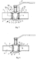
- the ready-assembled ball valve 1 with a reduced aperture shown in Figure 7 is described first.
- the ball valve 1 comprises the valve ball 2, which works as the joint body between two tubes 3, 4 with round cross-section, connected to the valve.
- the valve ball 2 is hollow, and it comprises ports 5, 6, which are slightly reduced in relation to the tubes and which in the Figure are turned towards the tube ends 7, 8 so that the flow channel 9 formed by the tubes 3, 4 is open.
- the element that keeps the ball valve 1 together consists of the sleeve-like cover 10 tapered from both ends by compression, i.e. the so-called valve body, the ends of which are attached to the flanks of the tubes 3, 4 with the welding joints 11, 12.
- the spindle 13 is fastened to the valve ball 2, the spindle being surrounded by the support sleeve 14 and provided with the handle 15.
- the support sleeve 14 is fitted to the aperture made for it in the cover 10 and attached to it by the welding joint 16.
- Closing the valve is performed by rotating the spindle 13 and the valve ball 2 rotating with it 90° from the position in the Figure, using the handle 15 so that the closed flanks of the valve ball rotate against the ends 7, 8 of the tubes 3, 4.
- the ends 7, 8 of the tubes are provided with the gaskets 17 against the ball valve 2 for preventing leakage.
- the steps according to the invention for the manufacture and assembly of the ball valve 1 with a reduced aperture appear from the Figures 1-7 in the drawings.
- the starting point is the cover blank 18 according to Figures 1 and 2, formed of the tube piece, the round seat 19 in the plane parallel to the longitudinal axis of the piece being machined to the cover blank for the subsequent fastening of the spindle 13 and its support sleeve 14.
- the aperture 20 is pierced at the place of the seat 19; the aperture can be seen in Figures 3-6 in the sleeve-like cover 10 of the valve, machined from the blank 18.
- the machining also comprises the bevelling of the edge 21 of the aperture 20 and the end faces 22, 23 of the generated cover 10 for the subsequent joining by beam welding.
- the conically bevelled end faces 22, 23 of the cover form an angle of 45° in relation to the axial direction of the tubes 3, 4.
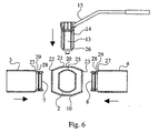
- FIG. 6 is a schematic presentation of the parts of the ball valve during the joining step.
- the end of the spindle 13 is attached to the hole 25 provided for it in the valve ball 2 so that the end face 26 of the support sleeve 14 of the spindle, bevelled similarly to the edge 21 of the aperture of the cover, is set to lean against the said edge.
- the tubes 3, 4 are brought to the interior of the cover so that the ends 7, 8 of the tubes are sealed against the valve ball 2.
- the flanks of both the tubes 3, 4 have the front face 29 rotating conically around the tube and being restricted by the folds 27, 28, the front face being machined in the angle of 45° in relation to the axial direction of the tube, similar to the end faces 22, 23 of the cover.
- the front faces 29 are set tightly against the end faces 22, 23 of the cover to be joined by beam welding the tubes and the cover.
- the said bringing together of the valve parts brings them to a position in relation to each other, in which they are in the finished ball valve 1 according to Figure 7.
- the joining together of the parts is performed by beam welding, and Figure 7 shows the source of radiation 30 and the welding beam 31, for example, laser beam generated by it in three different positions 30a-30c required by the welding of the joints 11, 12, 16.
- the inlet angle ⁇ of the welding beam 31 marked to the Figure is equal to the angle of 45° of the surfaces to be welded in relation to the axial direction of the tubes.
- the welds can be performed either by rotating the source of radiation 30 in relation to the stationary valve or keeping the source of radiation stationary and rotating the valve. It can be seen from Figure 7 that in the welding of the front faces 3, 4 of the tubes and the ends of the cover 10 the welding beam 13 penetrating the joint 11, 12 meets the material of the tube mantle, to which the travel of the beam stops.
- Figure 8 shows the finished beam-welded ball valve 1 with full aperture, which differs from the one shown in Figure 7 in that the ports 5, 6 of the valve ball 2 generally correspond to the cross-sectional area of the tubes 3, 4 so that, because of this, the flow channel 9 formed by the tubes penetrates the valve without choking.
- the mating comprises the expansion 32, which is conical seen from the direction of the tube and for which the cover 10 tapering towards its ends forms a direct continuation.
- the expansion 32 is followed by successive turns 27, 28, restricting between them the front face 29, which conically reduces the tube mantle, the end of the cover being attached to the front face 29 by beam welding as in the form of the embodiment described above, cf.
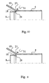
- Figures 9 and 10 are intended to illustrate the possibility offered by the invention to use cover parts 10 with similar material thickness in connection with tubes 4 with different material thickness.
- the material thickness of the cover 10 and the mantle of the tube 4 is essentially the same, when again in Figure 10, the cover 10, which is the same as in Figure 9, has a bigger material thickness than the mantle of the tube 4.
- the front face 29 restricted by the turns 27, 28 has similar dimensions in each case, and the beam welding by the welding beam 31 directed according to the surface can in both cases be performed using the same welding parameters.
Landscapes
- Engineering & Computer Science (AREA)
- General Engineering & Computer Science (AREA)
- Mechanical Engineering (AREA)
- Taps Or Cocks (AREA)
- Valve Housings (AREA)
- Multiple-Way Valves (AREA)
- Welding Or Cutting Using Electron Beams (AREA)
- Mechanically-Actuated Valves (AREA)
Abstract
Description
- The object of the invention is a method for the manufacture of a ball valve between two tubes, in which method the ends of the tubes are sealed against a rotatable valve ball opening and closing the valve, and the valve ball and the ends of the tubes are surrounded by a sleeve-like cover to be seamed to the mantle surfaces of the tubes.
- Ball valves are available in the markets provided with a full aperture, in which valve type the size of the ports of the valve ball approximately corresponds to the cross-section of the tubes sealed against the ball so that the valve does not substantially narrow the flow path formed by the tubes. In addition to these, ball valves with a reduced aperture are available in the markets, in which valves the ports are smaller than the cross-section of the flow path formed by the tubes. The operating principle of both the valve types is the same; the valve ball can be rotated around the axis perpendicular to the direction of the tubes with the help of a spindle connected to it so that the valve is open as the ports of the ball are turned towards the tubes and closed as the closed flanks of the ball are turned towards the tubes.
- The last step in assembling the ball valve is to attach the sleeve-like cover, which is also called the valve body, surrounding the valve ball and the tube ends to the flanks of the tube by welding. The spatters that are generated in the welding can then become a danger to the valve ball fitted to the interior of the cover and to the gaskets for the tube ends against the ball. Upon rotating the valve ball, the attached spatters can damage the gaskets.
- The patent specification US 5 890 286 of the applicant, which discloses the features of the preamble of claim 1, describes the manufacture of a ball valve with a full aperture, in which the tube ends coming against the valve ball are provided with a stepped projection, which forms the gasket housing for the gaskets for the tube ends without narrowing the flow path. As the welding joints attaching the valve body to the tube flanks remain behind the stepwise protruding ends of the tubes, seen from the direction of the valve ball, the projections act as spatter shields, preventing the welding spatters from getting to damage the valve ball and the gaskets. However, despite its advantages, the solution described in the specification does not provide a full protection against spatters. Further, the solution would be very difficult to apply to ball valves with reduced openings, if at all, and the specification does not contain such a description.
- The welding technique that is at present most often applied to the assembling of ball valves is the MIG welding performed by using a welding wire and inert shielding gas. In welding, the metal melts at the seam, and the welding wire melts as a part of the generated welding bead. Wire welding is strongly heat-generating, and besides the welding spatters already mentioned, also heating will be a danger to the gaskets for the tube ends. Deformations caused by heat and the irregular quality of the welding seam, in other words, the difficulties to achieve a seam of uniform quality and without root defects, lead to strength problems and to the exposure of the welding seams to corrosion.
- One central application of the ball valve are heating tubes, in which the valves have to endure stresses caused by the large variation of temperature. The regulations by authorities that are becoming more stringent, such as the application of the pressure vessel directive of the EU to valves, is leading to that it is no longer possible to meet the requirements of the most demanding categories with the ball valves manufactured using the state-of-the-art methods.
- The object of the present invention is to provide a solution, which eliminates the above-mentioned quality problems of the present ball valves and makes possible the manufacture of ball valves meeting the pressure vessel regulations in all respects. In addition, the invention relates to a manufacturing technique, which can be applied to the manufacture of ball valves with both full and reduced apertures. The characterising features of the invention are recited in the characterising part of claim 1.
- Thus, the solution of the invention comprises the machining of the faces of the tube and cover to be joined to each other so that they will fit tightly to each other, in which case the joining can be performed by beam welding, such as laser or electron beam welding, which is characterised in that no additional material is brought to the point of joining for achieving the welding joint. The joining is exclusively based on the welding beam having a melting effect on the faces to be joined to each other.
- Advantages of the beam welding are that the welding performance is fast and that substantially lower heat has to be brought to the structure to be welded. Thus, a welding joint of uniform quality without root defects is achieved, the strength of which is better and which meets the requirements relating to pressure vessels. As also the risk of spatters is small in beam welding, the welding joints can be brought nearer to the tube ends and the valve ball without causing risks to the gaskets. This again means that the cover surrounding the valve ball and the tube ends becomes even shorter, due to which material is saved and the structure can be made more rigid than before. A modular manufacturing technique can advantageously be used in the manufacture, within which it is possible to achieve a wide product range with simple means of variation.
- For the beam welding it is especially advantageous if the tube mantle contains turns or bends on both sides of the front face so that after penetrating the point of joining formed by the opposite faces, the welding beam hits the material of the tube mantle, to which it stops. The welding beam is then absorbed to the tube mantle so that the possibility of the spatters to spread along with the beam to the internal space of the cover is fully eliminated. The front face required by the solution can be advantageously provided with a step to be made to the tube mantle bevelled or perpendicular in relation to the axial direction.
- The alignment of the welding beam is easiest, if the bevelled front face of the tube mantle is in an angle of approximately 30-60°, preferably in an angle of 45° in relation to the axial direction of the tube. The laser radiator or some other radiation source can then be kept at a suitable distance from both the tube mantle and the spindle sleeve to be perpendicularly attached to the sleeve-like cover. The welding beam being in the said angles, tubes made of materials of different thickness can be connected to a similar valve cover, and the same welding parameters can thus be used for different tubes.
- According to the invention, also the said spindle with the surrounding sleeve rotating the valve ball can be installed in the valve using beam welding for the joining of the sleeve. An aperture has to be formed to the sleeve-like cover of the valve for the spindle and the sleeve surrounding it so that the edge of the aperture can be formed so that it is located in one plane parallel to the axis of the tubes. As the spindle with the surrounding sleeve is fitted into the aperture, the welding joint can be made in one plane in the beam welding in a way required by the quality requirements for beam welding. Also the mating faces of the edge of the aperture and the spindle sleeve to be joined together can be in an angle of 30-60°, preferably in an angle of 45° in relation to the axial direction of the tubes so that neither the spindle sleeve nor the tubes form an obstacle for the welding. If the said mating faces and the above-mentioned front face of the tube mantle are in the same angle in relation to the axial direction of the tubes, it is possible to perform the joining of the cover to the tube mantle and the joining of the sleeve surrounding the spindle to the cover successively without it being necessary to change the alignment of the source of the welding beam.
- The invention is next described in more detail with the help of examples, referring to the enclosed drawings, in which
- Figure 1 is a longitudinal section of the cover blank;
- Figure 2 is the cross-section II-II of the cover blank in Fig. 1;
- Figure 3 shows the forming of the cover blank to the sleeve-like cover of the ball valve with reciprocating moulding tools compressing the blank;
- Figure 4 shows the sleeve-like cover of the ball valve formed by compression and the valve ball in longitudinal section;
- Figure 5 is the cross-section V-V of the cover and valve ball in Fig. 4;
- Figure 6 shows the cover of the ball valve with its valve ball, the tubes to be connected to the valve ball, and the spindle rotating the valve ball with its support sleeves and handles before joining the said parts together;
- Figure 7 shows the parts in Fig. 6 assembled as a ball valve, which is joined by welding and provided with a reduced aperture, the Figure also depicting the sources of radiation and the welding beams directed from them to the welding joints;
- Figure 8 shows a second embodiment of the ball valve with a full aperture, joined by beam welding;
- Figure 9 shows the cover and the tube mantle welded to it, the material thickness of which is substantially the same, in enlarged scale; and
- Figure 10 is similar to Fig. 9, showing an embodiment, in which the material thickness of the cover is larger than that of the tube mantle.
- The ready-assembled ball valve 1 with a reduced aperture shown in Figure 7 is described first. The ball valve 1 comprises the
valve ball 2, which works as the joint body between twotubes 3, 4 with round cross-section, connected to the valve. Thevalve ball 2 is hollow, and it comprisesports flow channel 9 formed by thetubes 3, 4 is open. The element that keeps the ball valve 1 together consists of the sleeve-like cover 10 tapered from both ends by compression, i.e. the so-called valve body, the ends of which are attached to the flanks of thetubes 3, 4 with thewelding joints spindle 13 is fastened to thevalve ball 2, the spindle being surrounded by thesupport sleeve 14 and provided with thehandle 15. Thesupport sleeve 14 is fitted to the aperture made for it in thecover 10 and attached to it by the welding joint 16. Closing the valve is performed by rotating thespindle 13 and thevalve ball 2 rotating with it 90° from the position in the Figure, using thehandle 15 so that the closed flanks of the valve ball rotate against the ends 7, 8 of thetubes 3, 4. The ends 7, 8 of the tubes are provided with thegaskets 17 against theball valve 2 for preventing leakage. - The steps according to the invention for the manufacture and assembly of the ball valve 1 with a reduced aperture appear from the Figures 1-7 in the drawings. The starting point is the cover blank 18 according to Figures 1 and 2, formed of the tube piece, the
round seat 19 in the plane parallel to the longitudinal axis of the piece being machined to the cover blank for the subsequent fastening of thespindle 13 and itssupport sleeve 14. For thesupport sleeve 14 of the spindle, theaperture 20 is pierced at the place of theseat 19; the aperture can be seen in Figures 3-6 in the sleeve-like cover 10 of the valve, machined from the blank 18. The machining also comprises the bevelling of theedge 21 of theaperture 20 and the end faces 22, 23 of the generatedcover 10 for the subsequent joining by beam welding. The conically bevelled end faces 22, 23 of the cover form an angle of 45° in relation to the axial direction of thetubes 3, 4. - The forming of the cover blank 18 according to Figures 1 and 2 to the sleeve-
like cover 10 tapering conically towards itsends moulding tools 24, according to Figure 3. Thetools 24 are forced towards each other according to the arrows in Figure 3 until they bump into each other, after which the tools perform the return movement. Before compression thevalve ball 2 has been brought to the interior of the cover blank 18, supported to appropriate temporary support elements (not shown). Thevalve cover 10 machined to its finished form as the result of compression is shown in Figures 4 and 5. - Figure 6 is a schematic presentation of the parts of the ball valve during the joining step. The end of the
spindle 13 is attached to thehole 25 provided for it in thevalve ball 2 so that theend face 26 of thesupport sleeve 14 of the spindle, bevelled similarly to theedge 21 of the aperture of the cover, is set to lean against the said edge. From theends tubes 3, 4 are brought to the interior of the cover so that the ends 7, 8 of the tubes are sealed against thevalve ball 2. The flanks of both thetubes 3, 4 have thefront face 29 rotating conically around the tube and being restricted by thefolds tubes 3, 4 have been brought to place, the front faces 29 are set tightly against the end faces 22, 23 of the cover to be joined by beam welding the tubes and the cover. - The said bringing together of the valve parts brings them to a position in relation to each other, in which they are in the finished ball valve 1 according to Figure 7. The joining together of the parts is performed by beam welding, and Figure 7 shows the source of radiation 30 and the
welding beam 31, for example, laser beam generated by it in threedifferent positions 30a-30c required by the welding of thejoints welding beam 31 marked to the Figure is equal to the angle of 45° of the surfaces to be welded in relation to the axial direction of the tubes. The welds can be performed either by rotating the source of radiation 30 in relation to the stationary valve or keeping the source of radiation stationary and rotating the valve. It can be seen from Figure 7 that in the welding of the front faces 3, 4 of the tubes and the ends of thecover 10 thewelding beam 13 penetrating the joint 11, 12 meets the material of the tube mantle, to which the travel of the beam stops. - Figure 8 shows the finished beam-welded ball valve 1 with full aperture, which differs from the one shown in Figure 7 in that the
ports valve ball 2 generally correspond to the cross-sectional area of thetubes 3, 4 so that, because of this, theflow channel 9 formed by the tubes penetrates the valve without choking. In both thetubes 3, 4 the mating comprises theexpansion 32, which is conical seen from the direction of the tube and for which thecover 10 tapering towards its ends forms a direct continuation. Theexpansion 32 is followed bysuccessive turns front face 29, which conically reduces the tube mantle, the end of the cover being attached to thefront face 29 by beam welding as in the form of the embodiment described above, cf. Figures 6 and 7. - Figures 9 and 10 are intended to illustrate the possibility offered by the invention to use
cover parts 10 with similar material thickness in connection withtubes 4 with different material thickness. In Figure 9, the material thickness of thecover 10 and the mantle of thetube 4 is essentially the same, when again in Figure 10, thecover 10, which is the same as in Figure 9, has a bigger material thickness than the mantle of thetube 4. Thefront face 29 restricted by theturns welding beam 31 directed according to the surface can in both cases be performed using the same welding parameters. - It is obvious for one skilled in the art that the embodiments of the invention are not restricted to the examples described in detail above, but they may vary within the scope of the following claims.
Claims (10)
- Method for the manufacture of a ball valve (1) between two tubes (3, 4), the ends (7, 8) of the tubes (3, 4) being sealed against a rotatable valve ball (2) opening and closing the valve (1), and the valve ball (2) and the tub ends (7, 8) being surrounded by a sleeve-like cover (10) having end faces (22, 23) to be joined to the mantle surfaces of the tubes (3, 4),
characterised by the steps of:- forming a front face (29) of the mantle of each one of the two tubes (3; 4) by a bevelling or stepping, said bevelling or stepping narrowing said mantle towards the end (7, 8) of the tube (3; 4);- bevelling each one of the end faces (22, 23) of the sleeve-like cover (10) such that the bevelled end faces (22, 23) are directed similarly to the front face (29) of the mantle of the corresponding tube (3; 4);- bringing the front face (29) of the mantle of each tube (3; 4) against the corresponding end face (22, 23) of the sleeve-like cover (10);- joining the tubes (3; 4) and the sleeve-like cover (10) to each other by beam welding by directing the welding beam (31) between said faces (29, 29; 22, 23) brought against each other, following their direction. - Method according to claim 1, characterised in that the mantle of the tube (3, 4) has turns (27, 28) on both sides of the front face (29) so that the welding beam penetrating the joint (11, 12) formed by said respective faces (29, 29; 22, 23) brought against each other hits the turn and the material of the tube mantle below.
- Method according to claim 1 or 2, characterised in that the bevelled front face (29) of the mantle of the tube (3, 4) is in an angle of approximately 30-60°, preferably approximately 45° in relation to the axial direction of the tube (3, 4).
- Method according to one of the preceding claims, characterised in that it is used for the manufacture of a ball valve (1) with a reduced aperture (5, 6).
- Method according to one of the claims 1 - 3, characterised in that it is used for the manufacture of a ball valve (1) with full aperture so that the mantle of the tube (3, 4) has been expanded (32) and then narrowed for achieving the bevelled front face (29) for joining the sleeve-like cover (10).
- Method according to one of the preceding claims, characterised in that the cover (10) is attached to the mantle of the tube (3, 4) by laser welding (30, 31).
- Method according to one of the claims 1 - 5, characterised in that the cover (10) is attached to the mantle of the tube (3, 4) by electron beam welding.
- Method according to one of the preceding claims, characterised in that an aperture (20) is provided to the sleeve-like cover (10), to which aperture the spindle (13) rotating the valve ball (2) and the surrounding support sleeve (14) are fitted, the support sleeve (14) being joined to the edge (21) of the aperture by beam welding.
- Method according to claim 8, characterised in that the sleeve-like cover (10) is shaped so that the edge (21) of the aperture (20) is located in one plane parallel to the axis of the tubes (3, 4).
- Method according to claim 9, characterised in that the mating faces (21, 26) of the edge (21) of the aperture (20) and the support sleeve (14) of the spindle, which are joined together by beam welding, are in an angle of 30-60°, preferably approximately 45° in relation to the axial direction of the tubes (3, 4).
Applications Claiming Priority (3)
| Application Number | Priority Date | Filing Date | Title |
|---|---|---|---|
| FI20011081A FI115556B (en) | 2001-05-23 | 2001-05-23 | Process for producing a ball valve between two pipes |
| FI20011081 | 2001-05-23 | ||
| PCT/FI2002/000435 WO2002095274A1 (en) | 2001-05-23 | 2002-05-21 | Method for the manufacture of a ball valve between two tubes |
Publications (2)
| Publication Number | Publication Date |
|---|---|
| EP1390649A1 EP1390649A1 (en) | 2004-02-25 |
| EP1390649B1 true EP1390649B1 (en) | 2007-04-11 |
Family
ID=8561256
Family Applications (1)
| Application Number | Title | Priority Date | Filing Date |
|---|---|---|---|
| EP02724354A Expired - Lifetime EP1390649B1 (en) | 2001-05-23 | 2002-05-21 | Method for the manufacture of a ball valve between two tubes |
Country Status (9)
| Country | Link |
|---|---|
| US (1) | US20040117986A1 (en) |
| EP (1) | EP1390649B1 (en) |
| AT (1) | ATE359465T1 (en) |
| DE (1) | DE60219463D1 (en) |
| DK (1) | DK1390649T3 (en) |
| FI (1) | FI115556B (en) |
| PL (1) | PL363994A1 (en) |
| RU (1) | RU2003134540A (en) |
| WO (1) | WO2002095274A1 (en) |
Families Citing this family (13)
| Publication number | Priority date | Publication date | Assignee | Title |
|---|---|---|---|---|
| DE50208575D1 (en) * | 2001-06-15 | 2006-12-14 | Josch Strahlschweistechnik Gmb | Basic body of joined pipe sections and method for its production |
| DE10221105B3 (en) * | 2002-05-02 | 2004-02-19 | Klinger Ag | Ball for a ball valve |
| RU2334148C1 (en) * | 2006-11-07 | 2008-09-20 | Александр Павлович Андреев | Actuator valve |
| CN104033616A (en) * | 2013-03-05 | 2014-09-10 | 浙江三花股份有限公司 | Ball valve and combination method thereof |
| CN103615560A (en) * | 2013-10-29 | 2014-03-05 | 浙江国阀科技有限公司 | Laser-welded integrated ball valve |
| CN103672008A (en) * | 2013-11-28 | 2014-03-26 | 克里特集团有限公司 | Ball valve with all-welded valve bodies and welding method of ball valve |
| CN105402432A (en) * | 2015-12-09 | 2016-03-16 | 安徽铜都流体科技股份有限公司 | High-strength anti-leakage double-sealed welded ball valve |
| HUE051455T2 (en) | 2018-01-31 | 2021-03-01 | Samsung Sdi Co Ltd | Fixing element for a battery pack of a vehicle |
| EP3633249A1 (en) * | 2018-10-02 | 2020-04-08 | Continental Automotive GmbH | Fluid valve, vehicle, method for sealing |
| WO2020137247A1 (en) * | 2018-12-26 | 2020-07-02 | コスモ工機株式会社 | Fluid control device |
| KR102089497B1 (en) * | 2019-03-12 | 2020-03-17 | 화성밸브 주식회사 | Jig apparatus for assembling welding type ball valve using seat contact pressure reference method |
| EP3753668A1 (en) * | 2019-06-20 | 2020-12-23 | BROEN POLAND sp.z.o.o. | A method for making a ball valve for regulating a fluid, a ball valve and a welding tool for holding and handling valve parts |
| CN116025729A (en) * | 2022-12-16 | 2023-04-28 | 江苏威尔迪威阀业有限公司 | A welded ball valve with filter |
Family Cites Families (5)
| Publication number | Priority date | Publication date | Assignee | Title |
|---|---|---|---|---|
| US3677283A (en) * | 1970-04-16 | 1972-07-18 | Kostag V Tito | Ball valve |
| US3669406A (en) * | 1971-02-10 | 1972-06-13 | Pacific Valves Inc | Ball valve |
| DE2807740C2 (en) * | 1978-02-23 | 1986-12-11 | Forval S.A., Freiburg/Fribourg | Valve housing made of steel, in particular for gate valves |
| HU218184B (en) * | 1994-08-17 | 2000-06-28 | Naval Oy | A ball valve with full opening and a method for its manufacture |
| ITCO20000027A1 (en) * | 2000-12-29 | 2002-06-29 | Giacomini Spa | BALL VALVE PERFECTED IN PARTICULAR FOR GAS SYSTEMS. |
-
2001
- 2001-05-23 FI FI20011081A patent/FI115556B/en not_active IP Right Cessation
-
2002
- 2002-05-21 DE DE60219463T patent/DE60219463D1/en not_active Expired - Lifetime
- 2002-05-21 PL PL02363994A patent/PL363994A1/en unknown
- 2002-05-21 DK DK02724354T patent/DK1390649T3/en active
- 2002-05-21 EP EP02724354A patent/EP1390649B1/en not_active Expired - Lifetime
- 2002-05-21 WO PCT/FI2002/000435 patent/WO2002095274A1/en not_active Ceased
- 2002-05-21 AT AT02724354T patent/ATE359465T1/en not_active IP Right Cessation
- 2002-05-21 RU RU2003134540/06A patent/RU2003134540A/en not_active Application Discontinuation
-
2003
- 2003-11-18 US US10/716,083 patent/US20040117986A1/en not_active Abandoned
Also Published As
| Publication number | Publication date |
|---|---|
| RU2003134540A (en) | 2005-05-20 |
| EP1390649A1 (en) | 2004-02-25 |
| DK1390649T3 (en) | 2007-08-06 |
| FI115556B (en) | 2005-05-31 |
| ATE359465T1 (en) | 2007-05-15 |
| WO2002095274A1 (en) | 2002-11-28 |
| DE60219463D1 (en) | 2007-05-24 |
| PL363994A1 (en) | 2004-11-29 |
| FI20011081L (en) | 2002-11-24 |
| FI20011081A0 (en) | 2001-05-23 |
| US20040117986A1 (en) | 2004-06-24 |
Similar Documents
| Publication | Publication Date | Title |
|---|---|---|
| US20040117986A1 (en) | Method for the manufacture of a ball valve between two tubes | |
| US6786388B2 (en) | Friction stir welding method | |
| US6269870B1 (en) | Exhaust heat exchanger | |
| DE19907163C2 (en) | Heat exchanger, in particular exhaust gas heat exchanger | |
| US6397940B1 (en) | Method of joining at least four heat transfer plates to a plate package, and a plate package | |
| US10570951B2 (en) | Method for manufacture of a chassis module and chassis module manufactured according to such a method | |
| US7278473B2 (en) | Exhaust gas heat exchanger and method for the production thereof | |
| US5653478A (en) | Flexible coupling assembly | |
| CA2216290C (en) | Pressure vessel and method of manufacture thereof | |
| US5890286A (en) | Ball valve with full opening and a method for its manufacture | |
| US5168142A (en) | Method for fabricating a clutch cylinder-drum assembly | |
| JP6542447B1 (en) | Method and structure for joining resin pipe and resin member | |
| US20070237689A1 (en) | Catalytic converter and method for manufacture thereof | |
| US5487573A (en) | Unitary assembly of tubing and a pressed on, interference fit, terminating fitting | |
| KR20230012994A (en) | Process for improving the repeatability of a weld | |
| US7188417B2 (en) | Advanced L-channel welded nozzle design | |
| US20240210126A1 (en) | Radiator and joint | |
| GB2625611A (en) | Radiator and joint | |
| US20050062285A1 (en) | Hydraulic port weld stud | |
| JP3331550B2 (en) | Capillary tube line system and its manufacturing method and apparatus | |
| US11420298B2 (en) | Method of making a heat exchanger | |
| EP0741614B1 (en) | Hollow titanium blade manufacturing | |
| JPS6242228Y2 (en) | ||
| CN112984191A (en) | Valve body component, fluid control valve and manufacturing method | |
| JPH03128191A (en) | Production of branched pipe |
Legal Events
| Date | Code | Title | Description |
|---|---|---|---|
| PUAI | Public reference made under article 153(3) epc to a published international application that has entered the european phase |
Free format text: ORIGINAL CODE: 0009012 |
|
| 17P | Request for examination filed |
Effective date: 20031024 |
|
| AK | Designated contracting states |
Kind code of ref document: A1 Designated state(s): AT BE CH CY DE DK ES FI FR GB GR IE IT LI LU MC NL PT SE TR |
|
| AX | Request for extension of the european patent |
Extension state: AL LT LV MK RO SI |
|
| GRAP | Despatch of communication of intention to grant a patent |
Free format text: ORIGINAL CODE: EPIDOSNIGR1 |
|
| RIC1 | Information provided on ipc code assigned before grant |
Ipc: F16K 5/08 20060101ALN20060925BHEP Ipc: F16K 5/06 20060101AFI20060925BHEP |
|
| GRAS | Grant fee paid |
Free format text: ORIGINAL CODE: EPIDOSNIGR3 |
|
| GRAA | (expected) grant |
Free format text: ORIGINAL CODE: 0009210 |
|
| AK | Designated contracting states |
Kind code of ref document: B1 Designated state(s): AT BE CH CY DE DK ES FI FR GB GR IE IT LI LU MC NL PT SE TR |
|
| PG25 | Lapsed in a contracting state [announced via postgrant information from national office to epo] |
Ref country code: LI Free format text: LAPSE BECAUSE OF FAILURE TO SUBMIT A TRANSLATION OF THE DESCRIPTION OR TO PAY THE FEE WITHIN THE PRESCRIBED TIME-LIMIT Effective date: 20070411 Ref country code: FI Free format text: LAPSE BECAUSE OF FAILURE TO SUBMIT A TRANSLATION OF THE DESCRIPTION OR TO PAY THE FEE WITHIN THE PRESCRIBED TIME-LIMIT Effective date: 20070411 Ref country code: CH Free format text: LAPSE BECAUSE OF FAILURE TO SUBMIT A TRANSLATION OF THE DESCRIPTION OR TO PAY THE FEE WITHIN THE PRESCRIBED TIME-LIMIT Effective date: 20070411 |
|
| REG | Reference to a national code |
Ref country code: GB Ref legal event code: FG4D |
|
| REG | Reference to a national code |
Ref country code: CH Ref legal event code: EP |
|
| REG | Reference to a national code |
Ref country code: IE Ref legal event code: FG4D |
|
| REF | Corresponds to: |
Ref document number: 60219463 Country of ref document: DE Date of ref document: 20070524 Kind code of ref document: P |
|
| PG25 | Lapsed in a contracting state [announced via postgrant information from national office to epo] |
Ref country code: SE Free format text: LAPSE BECAUSE OF FAILURE TO SUBMIT A TRANSLATION OF THE DESCRIPTION OR TO PAY THE FEE WITHIN THE PRESCRIBED TIME-LIMIT Effective date: 20070711 |
|
| PG25 | Lapsed in a contracting state [announced via postgrant information from national office to epo] |
Ref country code: ES Free format text: LAPSE BECAUSE OF FAILURE TO SUBMIT A TRANSLATION OF THE DESCRIPTION OR TO PAY THE FEE WITHIN THE PRESCRIBED TIME-LIMIT Effective date: 20070722 |
|
| REG | Reference to a national code |
Ref country code: DK Ref legal event code: T3 |
|
| PG25 | Lapsed in a contracting state [announced via postgrant information from national office to epo] |
Ref country code: PT Free format text: LAPSE BECAUSE OF FAILURE TO SUBMIT A TRANSLATION OF THE DESCRIPTION OR TO PAY THE FEE WITHIN THE PRESCRIBED TIME-LIMIT Effective date: 20070911 |
|
| NLV1 | Nl: lapsed or annulled due to failure to fulfill the requirements of art. 29p and 29m of the patents act | ||
| REG | Reference to a national code |
Ref country code: CH Ref legal event code: PL |
|
| PG25 | Lapsed in a contracting state [announced via postgrant information from national office to epo] |
Ref country code: AT Free format text: LAPSE BECAUSE OF FAILURE TO SUBMIT A TRANSLATION OF THE DESCRIPTION OR TO PAY THE FEE WITHIN THE PRESCRIBED TIME-LIMIT Effective date: 20070411 |
|
| EN | Fr: translation not filed | ||
| PG25 | Lapsed in a contracting state [announced via postgrant information from national office to epo] |
Ref country code: BE Free format text: LAPSE BECAUSE OF FAILURE TO SUBMIT A TRANSLATION OF THE DESCRIPTION OR TO PAY THE FEE WITHIN THE PRESCRIBED TIME-LIMIT Effective date: 20070411 |
|
| PG25 | Lapsed in a contracting state [announced via postgrant information from national office to epo] |
Ref country code: NL Free format text: LAPSE BECAUSE OF FAILURE TO SUBMIT A TRANSLATION OF THE DESCRIPTION OR TO PAY THE FEE WITHIN THE PRESCRIBED TIME-LIMIT Effective date: 20070411 Ref country code: MC Free format text: LAPSE BECAUSE OF NON-PAYMENT OF DUE FEES Effective date: 20070531 Ref country code: DE Free format text: LAPSE BECAUSE OF FAILURE TO SUBMIT A TRANSLATION OF THE DESCRIPTION OR TO PAY THE FEE WITHIN THE PRESCRIBED TIME-LIMIT Effective date: 20070712 |
|
| PLBE | No opposition filed within time limit |
Free format text: ORIGINAL CODE: 0009261 |
|
| STAA | Information on the status of an ep patent application or granted ep patent |
Free format text: STATUS: NO OPPOSITION FILED WITHIN TIME LIMIT |
|
| 26N | No opposition filed |
Effective date: 20080114 |
|
| GBPC | Gb: european patent ceased through non-payment of renewal fee |
Effective date: 20070711 |
|
| PG25 | Lapsed in a contracting state [announced via postgrant information from national office to epo] |
Ref country code: IT Free format text: LAPSE BECAUSE OF FAILURE TO SUBMIT A TRANSLATION OF THE DESCRIPTION OR TO PAY THE FEE WITHIN THE PRESCRIBED TIME-LIMIT Effective date: 20070411 Ref country code: FR Free format text: LAPSE BECAUSE OF FAILURE TO SUBMIT A TRANSLATION OF THE DESCRIPTION OR TO PAY THE FEE WITHIN THE PRESCRIBED TIME-LIMIT Effective date: 20071207 Ref country code: GR Free format text: LAPSE BECAUSE OF FAILURE TO SUBMIT A TRANSLATION OF THE DESCRIPTION OR TO PAY THE FEE WITHIN THE PRESCRIBED TIME-LIMIT Effective date: 20070712 |
|
| PG25 | Lapsed in a contracting state [announced via postgrant information from national office to epo] |
Ref country code: GB Free format text: LAPSE BECAUSE OF NON-PAYMENT OF DUE FEES Effective date: 20070711 Ref country code: IE Free format text: LAPSE BECAUSE OF NON-PAYMENT OF DUE FEES Effective date: 20070521 |
|
| PG25 | Lapsed in a contracting state [announced via postgrant information from national office to epo] |
Ref country code: FR Free format text: LAPSE BECAUSE OF FAILURE TO SUBMIT A TRANSLATION OF THE DESCRIPTION OR TO PAY THE FEE WITHIN THE PRESCRIBED TIME-LIMIT Effective date: 20070411 |
|
| PG25 | Lapsed in a contracting state [announced via postgrant information from national office to epo] |
Ref country code: CY Free format text: LAPSE BECAUSE OF FAILURE TO SUBMIT A TRANSLATION OF THE DESCRIPTION OR TO PAY THE FEE WITHIN THE PRESCRIBED TIME-LIMIT Effective date: 20070411 |
|
| PG25 | Lapsed in a contracting state [announced via postgrant information from national office to epo] |
Ref country code: LU Free format text: LAPSE BECAUSE OF NON-PAYMENT OF DUE FEES Effective date: 20070521 |
|
| PG25 | Lapsed in a contracting state [announced via postgrant information from national office to epo] |
Ref country code: TR Free format text: LAPSE BECAUSE OF FAILURE TO SUBMIT A TRANSLATION OF THE DESCRIPTION OR TO PAY THE FEE WITHIN THE PRESCRIBED TIME-LIMIT Effective date: 20070411 |
|
| PGFP | Annual fee paid to national office [announced via postgrant information from national office to epo] |
Ref country code: DK Payment date: 20100527 Year of fee payment: 9 |
|
| REG | Reference to a national code |
Ref country code: DK Ref legal event code: EBP |
|
| PG25 | Lapsed in a contracting state [announced via postgrant information from national office to epo] |
Ref country code: DK Free format text: LAPSE BECAUSE OF NON-PAYMENT OF DUE FEES Effective date: 20110531 |