EP1389785A1 - Oxide magnetic material - Google Patents
Oxide magnetic material Download PDFInfo
- Publication number
- EP1389785A1 EP1389785A1 EP02771767A EP02771767A EP1389785A1 EP 1389785 A1 EP1389785 A1 EP 1389785A1 EP 02771767 A EP02771767 A EP 02771767A EP 02771767 A EP02771767 A EP 02771767A EP 1389785 A1 EP1389785 A1 EP 1389785A1
- Authority
- EP
- European Patent Office
- Prior art keywords
- powder
- ferrite
- group
- material powder
- magnet
- Prior art date
- Legal status (The legal status is an assumption and is not a legal conclusion. Google has not performed a legal analysis and makes no representation as to the accuracy of the status listed.)
- Granted
Links
Images




Classifications
-
- H—ELECTRICITY
- H01—ELECTRIC ELEMENTS
- H01F—MAGNETS; INDUCTANCES; TRANSFORMERS; SELECTION OF MATERIALS FOR THEIR MAGNETIC PROPERTIES
- H01F1/00—Magnets or magnetic bodies characterised by the magnetic materials therefor; Selection of materials for their magnetic properties
- H01F1/01—Magnets or magnetic bodies characterised by the magnetic materials therefor; Selection of materials for their magnetic properties of inorganic materials
- H01F1/03—Magnets or magnetic bodies characterised by the magnetic materials therefor; Selection of materials for their magnetic properties of inorganic materials characterised by their coercivity
- H01F1/12—Magnets or magnetic bodies characterised by the magnetic materials therefor; Selection of materials for their magnetic properties of inorganic materials characterised by their coercivity of soft-magnetic materials
- H01F1/34—Magnets or magnetic bodies characterised by the magnetic materials therefor; Selection of materials for their magnetic properties of inorganic materials characterised by their coercivity of soft-magnetic materials non-metallic substances, e.g. ferrites
-
- H—ELECTRICITY
- H01—ELECTRIC ELEMENTS
- H01F—MAGNETS; INDUCTANCES; TRANSFORMERS; SELECTION OF MATERIALS FOR THEIR MAGNETIC PROPERTIES
- H01F1/00—Magnets or magnetic bodies characterised by the magnetic materials therefor; Selection of materials for their magnetic properties
- H01F1/01—Magnets or magnetic bodies characterised by the magnetic materials therefor; Selection of materials for their magnetic properties of inorganic materials
- H01F1/03—Magnets or magnetic bodies characterised by the magnetic materials therefor; Selection of materials for their magnetic properties of inorganic materials characterised by their coercivity
- H01F1/032—Magnets or magnetic bodies characterised by the magnetic materials therefor; Selection of materials for their magnetic properties of inorganic materials characterised by their coercivity of hard-magnetic materials
- H01F1/10—Magnets or magnetic bodies characterised by the magnetic materials therefor; Selection of materials for their magnetic properties of inorganic materials characterised by their coercivity of hard-magnetic materials non-metallic substances, e.g. ferrites, e.g. [(Ba,Sr)O(Fe2O3)6] ferrites with hexagonal structure
- H01F1/11—Magnets or magnetic bodies characterised by the magnetic materials therefor; Selection of materials for their magnetic properties of inorganic materials characterised by their coercivity of hard-magnetic materials non-metallic substances, e.g. ferrites, e.g. [(Ba,Sr)O(Fe2O3)6] ferrites with hexagonal structure in the form of particles
-
- C—CHEMISTRY; METALLURGY
- C01—INORGANIC CHEMISTRY
- C01G—COMPOUNDS CONTAINING METALS NOT COVERED BY SUBCLASSES C01D OR C01F
- C01G49/00—Compounds of iron
- C01G49/0018—Mixed oxides or hydroxides
- C01G49/0054—Mixed oxides or hydroxides containing one rare earth metal, yttrium or scandium
-
- C—CHEMISTRY; METALLURGY
- C01—INORGANIC CHEMISTRY
- C01G—COMPOUNDS CONTAINING METALS NOT COVERED BY SUBCLASSES C01D OR C01F
- C01G49/00—Compounds of iron
- C01G49/009—Compounds containing iron, with or without oxygen or hydrogen, and containing two or more other elements
-
- C—CHEMISTRY; METALLURGY
- C04—CEMENTS; CONCRETE; ARTIFICIAL STONE; CERAMICS; REFRACTORIES
- C04B—LIME, MAGNESIA; SLAG; CEMENTS; COMPOSITIONS THEREOF, e.g. MORTARS, CONCRETE OR LIKE BUILDING MATERIALS; ARTIFICIAL STONE; CERAMICS; REFRACTORIES; TREATMENT OF NATURAL STONE
- C04B35/00—Shaped ceramic products characterised by their composition; Ceramics compositions; Processing powders of inorganic compounds preparatory to the manufacturing of ceramic products
- C04B35/01—Shaped ceramic products characterised by their composition; Ceramics compositions; Processing powders of inorganic compounds preparatory to the manufacturing of ceramic products based on oxide ceramics
- C04B35/26—Shaped ceramic products characterised by their composition; Ceramics compositions; Processing powders of inorganic compounds preparatory to the manufacturing of ceramic products based on oxide ceramics based on ferrites
- C04B35/2608—Compositions containing one or more ferrites of the group comprising manganese, zinc, nickel, copper or cobalt and one or more ferrites of the group comprising rare earth metals, alkali metals, alkaline earth metals or lead
- C04B35/2633—Compositions containing one or more ferrites of the group comprising manganese, zinc, nickel, copper or cobalt and one or more ferrites of the group comprising rare earth metals, alkali metals, alkaline earth metals or lead containing barium, strontium or calcium
-
- C—CHEMISTRY; METALLURGY
- C04—CEMENTS; CONCRETE; ARTIFICIAL STONE; CERAMICS; REFRACTORIES
- C04B—LIME, MAGNESIA; SLAG; CEMENTS; COMPOSITIONS THEREOF, e.g. MORTARS, CONCRETE OR LIKE BUILDING MATERIALS; ARTIFICIAL STONE; CERAMICS; REFRACTORIES; TREATMENT OF NATURAL STONE
- C04B35/00—Shaped ceramic products characterised by their composition; Ceramics compositions; Processing powders of inorganic compounds preparatory to the manufacturing of ceramic products
- C04B35/01—Shaped ceramic products characterised by their composition; Ceramics compositions; Processing powders of inorganic compounds preparatory to the manufacturing of ceramic products based on oxide ceramics
- C04B35/26—Shaped ceramic products characterised by their composition; Ceramics compositions; Processing powders of inorganic compounds preparatory to the manufacturing of ceramic products based on oxide ceramics based on ferrites
- C04B35/2683—Other ferrites containing alkaline earth metals or lead
-
- H—ELECTRICITY
- H01—ELECTRIC ELEMENTS
- H01F—MAGNETS; INDUCTANCES; TRANSFORMERS; SELECTION OF MATERIALS FOR THEIR MAGNETIC PROPERTIES
- H01F1/00—Magnets or magnetic bodies characterised by the magnetic materials therefor; Selection of materials for their magnetic properties
- H01F1/01—Magnets or magnetic bodies characterised by the magnetic materials therefor; Selection of materials for their magnetic properties of inorganic materials
- H01F1/03—Magnets or magnetic bodies characterised by the magnetic materials therefor; Selection of materials for their magnetic properties of inorganic materials characterised by their coercivity
- H01F1/032—Magnets or magnetic bodies characterised by the magnetic materials therefor; Selection of materials for their magnetic properties of inorganic materials characterised by their coercivity of hard-magnetic materials
- H01F1/10—Magnets or magnetic bodies characterised by the magnetic materials therefor; Selection of materials for their magnetic properties of inorganic materials characterised by their coercivity of hard-magnetic materials non-metallic substances, e.g. ferrites, e.g. [(Ba,Sr)O(Fe2O3)6] ferrites with hexagonal structure
-
- C—CHEMISTRY; METALLURGY
- C01—INORGANIC CHEMISTRY
- C01P—INDEXING SCHEME RELATING TO STRUCTURAL AND PHYSICAL ASPECTS OF SOLID INORGANIC COMPOUNDS
- C01P2004/00—Particle morphology
- C01P2004/60—Particles characterised by their size
- C01P2004/62—Submicrometer sized, i.e. from 0.1-1 micrometer
-
- C—CHEMISTRY; METALLURGY
- C01—INORGANIC CHEMISTRY
- C01P—INDEXING SCHEME RELATING TO STRUCTURAL AND PHYSICAL ASPECTS OF SOLID INORGANIC COMPOUNDS
- C01P2006/00—Physical properties of inorganic compounds
- C01P2006/11—Powder tap density
-
- C—CHEMISTRY; METALLURGY
- C01—INORGANIC CHEMISTRY
- C01P—INDEXING SCHEME RELATING TO STRUCTURAL AND PHYSICAL ASPECTS OF SOLID INORGANIC COMPOUNDS
- C01P2006/00—Physical properties of inorganic compounds
- C01P2006/42—Magnetic properties
-
- C—CHEMISTRY; METALLURGY
- C04—CEMENTS; CONCRETE; ARTIFICIAL STONE; CERAMICS; REFRACTORIES
- C04B—LIME, MAGNESIA; SLAG; CEMENTS; COMPOSITIONS THEREOF, e.g. MORTARS, CONCRETE OR LIKE BUILDING MATERIALS; ARTIFICIAL STONE; CERAMICS; REFRACTORIES; TREATMENT OF NATURAL STONE
- C04B2235/00—Aspects relating to ceramic starting mixtures or sintered ceramic products
- C04B2235/02—Composition of constituents of the starting material or of secondary phases of the final product
- C04B2235/30—Constituents and secondary phases not being of a fibrous nature
- C04B2235/32—Metal oxides, mixed metal oxides, or oxide-forming salts thereof, e.g. carbonates, nitrates, (oxy)hydroxides, chlorides
- C04B2235/3224—Rare earth oxide or oxide forming salts thereof, e.g. scandium oxide
-
- C—CHEMISTRY; METALLURGY
- C04—CEMENTS; CONCRETE; ARTIFICIAL STONE; CERAMICS; REFRACTORIES
- C04B—LIME, MAGNESIA; SLAG; CEMENTS; COMPOSITIONS THEREOF, e.g. MORTARS, CONCRETE OR LIKE BUILDING MATERIALS; ARTIFICIAL STONE; CERAMICS; REFRACTORIES; TREATMENT OF NATURAL STONE
- C04B2235/00—Aspects relating to ceramic starting mixtures or sintered ceramic products
- C04B2235/02—Composition of constituents of the starting material or of secondary phases of the final product
- C04B2235/30—Constituents and secondary phases not being of a fibrous nature
- C04B2235/32—Metal oxides, mixed metal oxides, or oxide-forming salts thereof, e.g. carbonates, nitrates, (oxy)hydroxides, chlorides
- C04B2235/327—Iron group oxides, their mixed metal oxides, or oxide-forming salts thereof
- C04B2235/3272—Iron oxides or oxide forming salts thereof, e.g. hematite, magnetite
- C04B2235/3274—Ferrites
-
- C—CHEMISTRY; METALLURGY
- C04—CEMENTS; CONCRETE; ARTIFICIAL STONE; CERAMICS; REFRACTORIES
- C04B—LIME, MAGNESIA; SLAG; CEMENTS; COMPOSITIONS THEREOF, e.g. MORTARS, CONCRETE OR LIKE BUILDING MATERIALS; ARTIFICIAL STONE; CERAMICS; REFRACTORIES; TREATMENT OF NATURAL STONE
- C04B2235/00—Aspects relating to ceramic starting mixtures or sintered ceramic products
- C04B2235/02—Composition of constituents of the starting material or of secondary phases of the final product
- C04B2235/30—Constituents and secondary phases not being of a fibrous nature
- C04B2235/32—Metal oxides, mixed metal oxides, or oxide-forming salts thereof, e.g. carbonates, nitrates, (oxy)hydroxides, chlorides
- C04B2235/3298—Bismuth oxides, bismuthates or oxide forming salts thereof, e.g. zinc bismuthate
-
- C—CHEMISTRY; METALLURGY
- C04—CEMENTS; CONCRETE; ARTIFICIAL STONE; CERAMICS; REFRACTORIES
- C04B—LIME, MAGNESIA; SLAG; CEMENTS; COMPOSITIONS THEREOF, e.g. MORTARS, CONCRETE OR LIKE BUILDING MATERIALS; ARTIFICIAL STONE; CERAMICS; REFRACTORIES; TREATMENT OF NATURAL STONE
- C04B2235/00—Aspects relating to ceramic starting mixtures or sintered ceramic products
- C04B2235/02—Composition of constituents of the starting material or of secondary phases of the final product
- C04B2235/30—Constituents and secondary phases not being of a fibrous nature
- C04B2235/34—Non-metal oxides, non-metal mixed oxides, or salts thereof that form the non-metal oxides upon heating, e.g. carbonates, nitrates, (oxy)hydroxides, chlorides
- C04B2235/3409—Boron oxide, borates, boric acids, or oxide forming salts thereof, e.g. borax
Definitions
- the present invention relates to an oxide magnetic material, and more particularly relates to a ferrite magnet powder, a magnet made of the magnet powder, and methods of making the magnet powder and the magnet.
- Ferrite is a generic term for any compound including an oxide of a divalent cationic metal and trivalent iron, and ferrite magnets have found a wide variety of applications in numerous types of rotating machines, loudspeakers, and so on.
- Typical materials for a ferrite magnet include Sr ferrites (SrFe 12 O 19 ) and Ba ferrites (BaFe 12 O 19 ) having a hexagonal magnetoplumbite structure.
- Sr ferrites SrFe 12 O 19
- Ba ferrites Ba ferrites having a hexagonal magnetoplumbite structure.
- Each of these ferrites is made of iron oxide and a carbonate of strontium (Sr), barium (Ba) or any other suitable element, and can be produced at a relatively low cost by a powder metallurgical process.
- a basic composition of an (M-type) ferrite having the magnetoplumbite structure is normally represented by the chemical formula AO ⁇ 6Fe 2 O 3 , where A is a metal element to be divalent cationic and is selected from the group consisting of Sr, Ba, and other suitable elements.
- the coercivity H cJ and J r of a Ba ferrite or an Sr ferrite can be increased by substituting a rare earth element such as La for a portion of Ba or a portion of Sr and by substituting Co for a portion of Fe (see Bull. Acad. Sci. USSR (Tranl.) phys. Sec. vol. 25 (1961) 1405-1408, Japanese Patent Application No. 8-306072 and Japanese Laid-Open Publication No. 10-149910).
- H cJ and J r thereof can be increased by substituting La for a portion of Sr and by substituting Co and Zn for a portion of Fe (see PCT International Application No. PCT/JP98/00764 (corresponding to PCT International Publication No. WO 98/38654).
- La and Co which are rather expensive materials, be added in small amounts to an Sr ferrite.
- Japanese Laid-Open Publication No. 11-307331 reports that when 0.05 mol or less of La, 0.05 mol or less of Co and Mn were added to an Sr ferrite, the loop squareness of the B-H curve thereof improved.
- the compaction process which is normally a costly manufacturing processing step, needs to be carried out in a short time.
- a dehydration process accounts for most of the compaction process time. To shorten the time it takes to carry out this dehydration process, a powder needs to be finely pulverized into particles with a relatively large size in a fine pulverization process, which should be performed before the compaction process. However, if the size of those fine particles is increased, then J r and H cJ decrease.
- the degree of alignment and the density of a powder should be raised to increase J r .
- the density may be increased if the powder is sintered at an elevated temperature.
- the high-temperature sintering process may cause an excessive grain growth and decreased H cJ .
- a primary object of the present invention is to provide a ferrite magnet that can be produced at a low manufacturing cost and that can still exhibit improved magnetic properties and a method of making such a ferrite magnet.
- a more specific object is to minimize the decrease in coercivity even when the sintering process is carried out at an elevated temperature.
- element La is substituted for a portion of element A in a ferrite having a hexagonal M-type magnetoplumbite structure AO ⁇ 6Fe 2 O 3 (where A is at least one element selected from the group consisting of Sr, Ba, Pb and Ca) and B (boron) is added thereto.
- the "alignment” means aligning the crystallographic orientations of respective crystal grains in a polycrystalline structure.
- the sintering temperature is raised to increase the density of the sintered magnet, then grain growth advances noticeably to decrease the coercivity H cJ .
- an M-type ferrite makes a pinning type magnet. In such a magnet, the greater the crystal grain size, the lower the coercivity.
- an increased aligning magnetic field needs to be applied while the powder is being compacted.
- the aligning magnetic field should be increased, then the size of presses needs to be increased, thus increasing the manufacturing cost. In that case, the ferrite magnet cannot be produced at a low cost. That is to say, the major advantage of the ferrite magnet is sacrificed.
- the present inventors discovered that if La is substituted for a portion of Sr, Ba, Pb or Ca in a ferrite having a hexagonal M-type magnetoplumbite structure, if B is added thereto, and if the percentages of those additives and the manufacturing conditions thereof are adjusted appropriately, then even a high sintering temperature still results in just slight decrease in coercivity H cJ and sufficient increase in density and magnetization J r . This is the basic idea of the present invention.
- the present inventors discovered and confirmed via experiments that if only one of La and B was added, the magnetic properties did not improve but that only when La and B were both added in appropriate amounts, even a high-temperature sintering process resulted in almost no decrease in coercivity.
- B has been regarded as one of additives that promote the grain growth during the sintering process. Accordingly, those skilled in the art have naturally expected that the additive B should decrease the coercivity.
- both of La and B were added in appropriate amounts the coercivity hardly decreased against those expectations but the magnetization rather increased.
- An oxide magnetic material according to the present invention is a ferrite having a substantially magnetoplumbite structure, which is represented by (1-x) AO ⁇ (x/2) R 2 O 3 ⁇ n (Fe 2 O 3 ) ⁇ y (B 2 O 3 ), where A is at least one element that is selected from the group consisting of Sr, Ba, Pb and Ca. If Sr is selected as A, then the magnetic properties improve more significantly than the situation where Ba, Pb or Ca is selected as A. Accordingly, Sr is preferably selected as A. However, Ba, Pb or Ca would be more advantageous than Sr depending on the specific application, because the cost would be lower in that case.
- R is at least one element that is selected from the group consisting of the rare earth elements, including Y, and Bi.
- La is preferably selected as R because the magnetic properties improve most significantly in that case.
- any other element may be selected from that group to reduce the cost.
- x, y and n represent mole fractions and are preferably satisfy 0.01 ⁇ x ⁇ 0.05, 0.001 ⁇ y ⁇ 0.05, and 5.2 ⁇ n ⁇ 6.2, respectively.
- x and y satisfy 0.02 ⁇ x ⁇ 0.04 and 0.005 ⁇ y ⁇ 0.03, respectively.
- the mole fraction n preferably satisfies 5.2 ⁇ n ⁇ 6.2 and more preferably satisfies 5.7 ⁇ n ⁇ 6.1.
- the percentages of the constituents A, R, Fe and B to the sum of these elements preferably satisfy 7.04 at% ⁇ A ⁇ 8.68 at%, 0.07 at% ⁇ R ⁇ 0.44 at%, 90.4 at% ⁇ Fe ⁇ 92.5 at%, and 0.015 at% ⁇ B ⁇ 0.87 at%, respectively.
- the following additives are preferably added in the following amounts:
- a powder of at least one compound that is selected from the group consisting of SrCO 3 , BaCO 3 , PbO and CaCO 3 , a powder of Fe 2 O 3 , an oxide powder of at least one element (which will be referred to herein as an "element R") that is selected from the group consisting of Y (yttrium), the rare earth elements and Bi, and a powder of H 3 BO 3 or B 2 O 3 are mixed together.
- the element R may be added as an oxide powder of any of those elements.
- the element R may also be added as a powder or a solution of a compound that will be oxidized in the subsequent calcining process (e.g., carbonates, hydroxides, nitrates and chlorides).
- a compound including at least two elements that are selected from the group consisting of Sr, Ba, Pb, Ca, the rare earth elements including Y, Bi, Co, Cu and Fe, may also be added.
- any other compound e.g., a compound including Si, Ca, Pb, Al, Ga, Cr, Sn, In, Co, Ni, Ti, Mn, Cu, Ge, V, Nb, Zr, Li and/or Mo
- the material powder mixture may further include very small amounts of impurities such as inevitable components.
- the process step of preparing a material powder mixture refers to not only a situation where such a material powder mixture is prepared from the beginning but also a situation where a material powder mixture, prepared by somebody else, is purchased and used and a situation where a material powder made by somebody else is added to the mixture.
- the material powder mixture is heated to a temperature of 1,100 °C to 1,300 °C by using a batch furnace, a continuous furnace, or a rotary kiln, for example, thereby producing a ferrite compound having an M-type magnetoplumbite structure through a solid-phase reaction.
- This process will be referred to herein as "calcining” and a compound obtained by this process will be referred to herein as a "calcined body”.
- the calcining process may be carried out for a period of time of about 1 second to about 10 hours, preferably from 0.1 hour to 3 hours.
- a ferrite phase is gradually formed through the solid phase reaction.
- the formation of the ferrite phase is completed at about 1,100 °C. If the calcining process is finished at a temperature lower than about 1,100 °C, then unreacted hematite will be left to deteriorate the resultant magnetic properties.
- the effects of the present invention are achieved if the calcining temperature exceeds 1,100 °C. However, the effects of the present invention are relatively modest if the calcining temperature is in the range of 1,100 °C to 1,150 °C, but increases as the calcining temperature exceeds this range. However, if the calcining temperature is higher than 1,300 °C, then various inconveniences might be created. For example, crystal grains might grow so much that it would take a lot of time to pulverize the powder in the subsequent pulverizing process step.
- the calcining temperature is preferably in the range of 1,100 °C to 1,300 °C, more preferably in the range of 1,150 °C to 1,250 °C.
- the calcined body obtained by any of these calcining processes is a ferrite having a substantially M-type magnetoplumbite structure.
- a ferrite magnet powder according to the present invention can be obtained.
- the mean particle size thereof is preferably in the range of 0.5 ⁇ m to 1.5 ⁇ m. If the powder is too fine, then it would take too much time to dehydrate the powder being wet-pressed, thus increasing the cost adversely. For that reason, the mean particle size is more preferably in the range of 0.6 ⁇ m to 1.5 ⁇ m. An even more preferable range of the mean particle size is 0.8 ⁇ m to 1.5 ⁇ m.
- the calcined body of an M-type magnetoplumbite ferrite is prepared by the method described above.
- CaCO 3 , SiO 2 , CoO, cobalt hydroxide, Cr 2 O 3 , Al 2 O 3 , SrCO 3 and BaCO 3 (specifically, 0.3 wt% to 1.5 wt% of CaCO 3 , 0.2 wt% to 1.0 wt% of SiO 2 , 0 wt% to 0.4 wt% of CoO, 0 wt% to 5.0 wt% of Cr 2 O 3 , 0 wt% to 5.0 wt% of Al 2 O 3 , 0 wt% to 3.0 wt% of SrCO 3 and 0 wt% to 3.0 wt% of BaCO 3 ) are added to the calcined body: Thereafter, the calcined body is subjected to a fine pulverization process using a roller mill, a vibr
- the fine powder particles more preferably have a mean particle size of 0.8 ⁇ m to 1.5 ⁇ m (as measured by the air permeability method), even more preferably 0.8 ⁇ m to 1.3 ⁇ m.
- the fine pulverization process is preferably carried out as a combination of dry pulverization (i.e., coarse pulverization to a size of greater than 1.6 ⁇ m) and wet pulverization (i.e., fine pulverization to a size of 1.6 ⁇ m or less).
- 0 wt% to 0.4 wt% of cobalt hydroxide is preferably added to the calcined body to improve the magnetic properties.
- the wet pulverization process may be carried out with an aqueous solvent such as water or any of various non-aqueous solvents.
- an aqueous solvent such as water or any of various non-aqueous solvents.
- slurry is produced as a mixture of the solvent and the powder of the calcined body.
- Any of various known dispersants or surfactants is preferably added to the slurry at a solid matter ratio of 0.1 wt% to 2.0 wt%.
- the slurry is compacted with or without a magnetic field applied thereto, while the solvent is removed from the slurry.
- the slurry may be subjected to drying, crushing and granulating process steps, and then compacted with or without a magnetic field applied thereto.
- the compact is subjected to various known manufacturing processing steps including degreasing, sintering, machining, cleaning and testing to obtain a ferrite magnet as a final product.
- the sintering process may be carried out in the air at a temperature of 1,150 °C to 1,300 °C for 0.1 hour to 2 hours. If the fine powder particles have a mean particle size of 0.8 ⁇ m or more, the grain growth does not occur so easily even at an increased sintering temperature. For that reason, the sintering temperature is preferably 1,230 °C or more. More preferably, the sintering temperature is in the range of 1,230 °C to 1,260 °C.
- the sintered magnet to be obtained by the sintering process may have a mean particle size of 0.7 ⁇ m to 2.0 ⁇ m, for example.
- a rotating machine according to the present invention is characterized by including a ferrite magnet produced by the method described above.
- the specific structure thereof may be the same as that of a known rotating machine.
- various material powders including an SrCO 3 powder, an La 2 O 3 powder, an Fe 2 O 3 powder (with a particle size of 0.6 ⁇ m) and an H 3 BO 3 powder, were mixed together such that a composition (1-x) SrO ⁇ (x/2) La 2 O 3 ⁇ n (Fe 2 O 3 ) ⁇ y (B 2 O 3 ) would satisfy 0.00 ⁇ x ⁇ 0.1, 0.000 ⁇ y ⁇ 0.15 and 5.0 ⁇ n ⁇ 6.5.
- H 3 BO 3 was added in a greater amount than finally needed because B (boron) would vaporize during the calcining and sintering processes.
- the resultant material powder mixture was pulverized with a wet ball mill for four hours, dried, and then sieved. Thereafter, the powder was calcined in the air at 1,200 °C for one hour, thereby obtaining a calcined body magnet powder.
- the slurry was compacted within a magnetic field (of which the magnetizing direction was parallel to the pressing direction and which had a field strength of 13 kOe).
- the powder compact was sintered in the air at 1,220 °C for one hour to obtain a sintered magnet.
- the magnetization J r and coercivity H cJ of the resultant sintered magnet were measured. The results are shown in FIGS. 1 through 3. Approximately half of B vaporizes during the calcining and sintering processes. Thus, the y values were obtained by analyzing the sintered body.
- FIG. 1 shows the results of measurement that were obtained when y and n were fixed at 0.01 and 5.9, respectively, and when x was changed in the range of 0 to 0.1. As is clear from FIG. 1, excellent properties were achieved when x was in the range of 0.01 to 0.05.
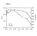
- FIG. 2 shows the results of measurement that were obtained when x and n were fixed at 0.03 and 5.9, respectively, and when y was changed in the range of 0 to 0.15.
- excellent properties are achieved when y is in the range of 0.002 to 0.03.
- B is in the range of 0.03 at% to 0.50 at%.
- a more preferable y range is 0.004 to 0.02.
- B is in the range of 0.06 at% to 0.35 at%.
- FIG. 3 shows the data that were obtained when x and y were fixed at 0.03 and 0.01, respectively, and when n was changed in the range of 5.0 to 6.5. As is clear from FIG. 3, excellent properties were achieved when n was in the range of 5.2 to 6.2.
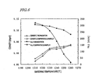
- the J r and H cJ values of the resultant sintered magnet were also measured. The results are shown in FIG. 4. As is clear from FIG. 4, excellent properties were achieved when the calcining temperature was in the range of 1,100 °C to 1,300 °C. It can also be seen that both J r and H cJ were particularly high when the calcining temperature was in the range of 1,150 °C to 1,250 °C.
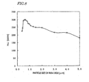
- the J r and H cJ values of the resultant sintered magnet were also measured. The results are shown in FIG. 5. As is clear from FIG. 5, excellent properties were achieved when the particle size of the pulverized powder was in the range of 0.6 ⁇ m to 1.5 ⁇ m.
- the time that it takes to complete dehydration during the compaction process shortens steeply at a particle size of 0.8 ⁇ m or more. More specifically, if the particle size is 0.8 ⁇ m, the dehydration finishes in approximately a half amount of time compared to the situation where the particle size is 0.6 ⁇ m. Accordingly, by setting the particle size to 0.8 ⁇ m or more, the compaction cycle can be halved and the productivity can be doubled compared to the situation where the particle size is 0.6 ⁇ m. It can be seen that the particle size is preferably in the range of 0.8 ⁇ m to 1.5 ⁇ m, more preferably in the range of 0.8 ⁇ m to 1.3 ⁇ m, to improve the magnetic properties.
- H k is a magnetic field at which the J value is 95% of the J r value as measured with a B-H tracer.
- the J r and H cJ values of the resultant sintered magnet were measured.
- a C-shaped sintered magnet for use in motors was produced by the method described above and embedded in a motor instead of a sintered magnet made of the conventional material, and then the motor was operated under rated conditions. As a result, good characteristics were achieved. Also; the torque thereof was higher than that of the motor including the sintered magnet made of the conventional material.
- H cJ was high when the material particle size of iron oxide was in the range of 0.5 ⁇ m to 0.8 ⁇ m.
- La is substituted for a portion of Sr, Ba, Pb or Ca in a ferrite having a hexagonal M-type magnetoplumbite structure and an appropriate amount of B is added thereto. Then, even at a high sintering temperature, H cJ hardly decreases and a high density and a high magnetization are achieved. Also, by setting the particle size of the pulverized powder to 0.8 ⁇ m or more, the performance of the magnet can be improved and yet dehydration can be completed in a short time during the compaction process. Thus, a high-performance ferrite magnet can be provided at a low manufacturing cost.
Landscapes
- Chemical & Material Sciences (AREA)
- Engineering & Computer Science (AREA)
- Organic Chemistry (AREA)
- Ceramic Engineering (AREA)
- Power Engineering (AREA)
- Manufacturing & Machinery (AREA)
- Materials Engineering (AREA)
- Structural Engineering (AREA)
- Inorganic Chemistry (AREA)
- Life Sciences & Earth Sciences (AREA)
- General Life Sciences & Earth Sciences (AREA)
- Geology (AREA)
- Dispersion Chemistry (AREA)
- Hard Magnetic Materials (AREA)
- Magnetic Ceramics (AREA)
- Compounds Of Iron (AREA)
Abstract
Description
- 7.04 at%≦A≦8.68 at%;
- 0.07 at%≦R≦0.44 at%;
- 90.4 at%≦Fe≦92.5 at%; and
- 0.015 at%≦B≦0.87 at%
preparing a material powder mixture by mixing: a material powder of at least one compound that is selected from the group consisting of SrCO3, BaCO3, PbO and CaCO3; a material powder of at least one oxide that is selected from the group consisting of an oxide of Y, oxides of the rare earth elements and Bi2O3; a material powder of Fe2O3 (iron oxide); and a material powder of B2O3 or H3BO3, and
calcining the material powder mixture at a temperature of 1,100 °C to 1,300 °C, thereby forming a ferrite calcined body having a composition represented by the general formula:
0.01 ≦x≦0.05,
0.001≦y≦0.05, and
5.2≦n≦6.2, respectively.
7.04 at% ≦ A ≦ 8.68 at%,
0.07 at% ≦ R ≦ 0.44 at%,
90.4 at% ≦ Fe ≦ 92.5 at%, and
0.015 at% ≦ B ≦ 0.87 at%, respectively.
| Jr (T) | HcJ (kA/m) | |
| Co3O4 | 0.427 | 299 |
| Cobalt hydroxide (divalent) | 0.429 | 311 |
| Cobalt hydroxide (trivalent) | 0.430 | 315 |
| Jr (T) | HcJ (kA/m) | |
| Polycarbonate added | 0.432 | 286 |
| No polycarbonate added | 0.427 | 299 |
Claims (15)
- An oxide magnetic material including, as a main phase, a ferrite having a hexagonal M-type magnetoplumbite structure, the material comprising:wherein the constituents A, R, Fe and B of the oxide magnetic material satisfy the inequalities of:A, which is at least one element that is selected from the group consisting of Sr, Ba, Pb and Ca;R, which is at least one element that is selected from the group consisting of Y (yttrium), the rare earth elements and Bi;Fe; andB (boron),to the sum of the elements A, R, Fe and B.7.04 at%≦A≦8.68 at%;0.07 at%≦R≦0.44 at%;90.4 at%≦Fe≦92.5 at%; and0.015 at%≦B≦0.87 at%
- The oxide magnetic material of claim 1, wherein the material is represented by the general formula
- A ferrite magnet powder including the oxide magnetic material of claim 1 or 2.
- A sintered magnet, which is made of the ferrite magnet powder of claim 3 and which includes CaO, SiO2, CoO, Cr2O3, Al2O3, SrO and BaO at the percentages of:0.3 wt% to 1.5 wt% (CaO),0.2 wt% to 1.0 wt% (SiO2),0 wt% to 0.4 wt% (CoO),0 wt% to 5.0 wt% (Cr2O3),0 wt% to 5.0 wt% (Al2O3),0 wt% to 3.0 wt% (SrO), and0 wt% to 3.0 wt% (BaO), respectively.
- A method of making a ferrite calcined body, the method comprising the steps of
preparing a material powder mixture by mixing: a material powder of at least one compound that is selected from the group consisting of SrCO3, BaCO3, PbO and CaCO3; a material powder of at least one oxide that is selected from the group consisting of an oxide of Y, oxides of the rare earth elements and Bi2O3; a material powder of Fe2O3 (iron oxide); and a material powder of B2O3 or H3BO3, and
calcining the material powder mixture at a temperature of 1,100 °C to 1,300 °C, thereby forming a ferrite calcined body having a composition represented by the general formula: - The method of claim 5, comprising the step of preparing the material powder of Fe2O3 (iron oxide) having a particle size of 0.5 µm to 0.8 µm when the size is measured by an air permeability method.
- A method of making a magnet powder, the method comprising the steps of:preparing a calcined body mixed powder by adding 0.3 wt% to 1.5 wt% of CaCO3, 0.2 wt% to 1.0 wt% of SiO2, 0 wt% to 0.4 wt% of CoO, 0 wt% to 0.4 wt% of cobalt hydroxide, 0 wt% to 5.0 wt% of Cr2O3, 0 wt% to 5.0 wt% of Al2O3, 0 wt% to 3.0 wt% of SrCO3 and 0 wt% to 3.0 wt% of BaCO3 to the calcined body that has been made by the method of claim 5 or 6; andpulverizing the calcined body mixed powder to obtain a ferrite pulverized powder having a mean particle size of 0.5 µm to 1.5 µm when the size is measured by an air permeability method.
- The method of claim 7, comprising the step of obtaining the ferrite pulverized powder having a mean particle size of 0.8 µm to 1.3 µm when the size is measured by the air permeability method.
- A method of producing a sintered magnet, the method comprising the steps of:preparing a material powder mixture by mixing: a material powder of at least one compound that is selected from the group consisting of SrCO3, BaCO3, PbO and CaCO3; a material powder of at least one oxide that is selected from the group consisting of an oxide of Y, oxides of the rare earth elements and Bi2O3; a material powder of Fe2O3 (iron oxide); and a material powder of B2O3 or H3BO3;calcining the material powder mixture at a temperature of 1,100 °C to 1,300 °C, thereby forming a ferrite calcined body having a composition represented by the general formula: (1-x) AO· (x/2) R2O3· n (Fe2O3)· y (B2O3) where A is at least one element selected from the group consisting of Sr, Ba, Pb and Ca; R is at least one element selected from the group consisting of the rare earth elements, including Y, and Bi; 0.01≦x≦0.05; 0.001≦y≦0.05; and 5.2≦n≦6.2;preparing a calcined body mixed powder by adding 0.3 wt% to 1.5 wt% of CaCO3, 0.2 wt% to 1.0 wt% of SiO2, 0 wt% to 0.4 wt% of CoO, 0 wt% to 0.4 wt% of cobalt hydroxide, 0 wt% to 5.0 wt% of Cr2O3, 0 wt% to 5.0 wt% of Al2O3, 0 wt% to 3.0 wt% of SrCO3 and 0 wt% to 3.0 wt% of BaCO3 to the ferrite calcined body;pulverizing the calcined body mixed powder in an aqueous solvent, thereby obtaining a slurry of a ferrite pulverized powder having a mean particle size of 0.5 µm to 1.5 µm when the size is measured by an air permeability method; andcondensing, mulling, compacting and sintering the slurry, where the slurry is compacted with or without a magnetic field applied thereto.
- The method of claim 9, wherein the step of pulverizing or the step of mulling includes the step of adding a dispersant at a solid matter ratio of 0.1 wt% to 2.0 wt%.
- The method of claim 9 or 10, wherein the step of sintering is carried out at a temperature of 1,230 °C or more.
- A sintered magnet produced by the method of one of claims 9 to 11.
- A sintered magnet that is produced by the method of one of claims 9 to 11 and that has a density of 5.02 Mg/m3 or more.
- A sintered magnet that is produced by the method of one of claims 9 to 11 and that has a loop squareness of 95% or more.
- A rotating machine comprising the sintered magnet of one of claims 4, 12, 13 and 14.
Applications Claiming Priority (3)
| Application Number | Priority Date | Filing Date | Title |
|---|---|---|---|
| JP2001156085 | 2001-05-24 | ||
| JP2001156085A JP4576751B2 (en) | 2001-05-24 | 2001-05-24 | Magnetic oxide material |
| PCT/JP2002/004922 WO2002095772A1 (en) | 2001-05-24 | 2002-05-21 | Oxide magnetic material |
Publications (3)
| Publication Number | Publication Date |
|---|---|
| EP1389785A1 true EP1389785A1 (en) | 2004-02-18 |
| EP1389785A4 EP1389785A4 (en) | 2010-08-25 |
| EP1389785B1 EP1389785B1 (en) | 2016-11-30 |
Family
ID=19000144
Family Applications (1)
| Application Number | Title | Priority Date | Filing Date |
|---|---|---|---|
| EP02771767.7A Expired - Lifetime EP1389785B1 (en) | 2001-05-24 | 2002-05-21 | Oxide magnetic material |
Country Status (6)
| Country | Link |
|---|---|
| US (1) | US6902685B2 (en) |
| EP (1) | EP1389785B1 (en) |
| JP (1) | JP4576751B2 (en) |
| KR (1) | KR100909702B1 (en) |
| CN (1) | CN1264172C (en) |
| WO (1) | WO2002095772A1 (en) |
Families Citing this family (11)
| Publication number | Priority date | Publication date | Assignee | Title |
|---|---|---|---|---|
| RU2361307C2 (en) * | 2007-05-28 | 2009-07-10 | Геннадий Павлович Левашов | Smelted magnetic medium on basis of hard-magnetic alloy and method of manufacturing from it of monolithic magnetic circuits of electric machines |
| JP5332185B2 (en) * | 2007-11-16 | 2013-11-06 | ソニー株式会社 | Magnetic powder manufacturing method, magnetic sheet manufacturing method, and antenna module manufacturing method |
| RU2390864C1 (en) * | 2008-11-18 | 2010-05-27 | Институт физики им. Л.В. Киренского Сибирского отделения РАН | Method of nano-magnet-ceramic production |
| CN104575910B (en) * | 2015-02-06 | 2017-05-24 | 江苏新旭磁电科技有限公司 | Magnetic Materials for Electrical Engineering |
| JP7087465B2 (en) * | 2018-03-07 | 2022-06-21 | Tdk株式会社 | A method for manufacturing a ferrite sintered magnet, a method for manufacturing ferrite particles, and a method for manufacturing a bonded magnet. |
| JP7087464B2 (en) * | 2018-03-07 | 2022-06-21 | Tdk株式会社 | A method for manufacturing a ferrite sintered magnet, a method for manufacturing ferrite particles, and a method for manufacturing a bonded magnet. |
| JP7358758B2 (en) * | 2019-03-27 | 2023-10-11 | Tdk株式会社 | Ferrite sintered magnet and rotating electric machine equipped with the same |
| JPWO2022203005A1 (en) * | 2021-03-25 | 2022-09-29 | ||
| KR20240147661A (en) * | 2022-02-10 | 2024-10-08 | 도다 고교 가부시끼가이샤 | Ferrite particle powder for electromagnetic wave absorption, method for producing the same, and resin composition using the same |
| CN116621572B (en) * | 2023-04-04 | 2024-08-16 | 宜宾四川大学产业技术研究院 | Preparation method of economic composite permanent magnetic ferrite |
| CN117534457B (en) * | 2023-11-21 | 2025-12-16 | 重庆科技学院 | Low-temperature high-coercivity permanent magnetic ferrite and production process thereof |
Family Cites Families (10)
| Publication number | Priority date | Publication date | Assignee | Title |
|---|---|---|---|---|
| JPS63186402A (en) | 1987-01-28 | 1988-08-02 | Sumitomo Special Metals Co Ltd | Ferrite magnet |
| DE3726667A1 (en) * | 1987-08-11 | 1989-02-23 | Bayer Ag | FINE-PART MAGNETIC BORCH HEXAFERRIT PIGMENTS, METHOD FOR THE PRODUCTION AND USE THEREOF |
| JPH01283802A (en) | 1988-05-10 | 1989-11-15 | Minebea Co Ltd | Strontium ferrite magnet |
| JP2908631B2 (en) * | 1992-03-25 | 1999-06-21 | 住友特殊金属株式会社 | Manufacturing method of ferrite magnet |
| JP2897871B2 (en) * | 1995-08-11 | 1999-05-31 | ティーディーケイ株式会社 | Magnet powder, sintered magnet, bonded magnet and magnetic recording medium |
| JP2922864B2 (en) | 1996-11-18 | 1999-07-26 | 日立金属株式会社 | Ferrite magnet and manufacturing method thereof |
| US6139766A (en) * | 1997-02-25 | 2000-10-31 | Tdk Corporation | Oxide magnetic material, ferrite particle, sintered magnet, bonded magnet, magnetic recording medium and motor |
| JPH11307331A (en) | 1998-04-24 | 1999-11-05 | Hitachi Metals Ltd | Ferrite magnet |
| JP3488416B2 (en) * | 1999-07-07 | 2004-01-19 | Tdk株式会社 | Manufacturing method of ferrite magnet |
| JP4194013B2 (en) * | 1999-10-06 | 2008-12-10 | Tdk株式会社 | Ferrite magnet manufacturing method |
-
2001
- 2001-05-24 JP JP2001156085A patent/JP4576751B2/en not_active Expired - Lifetime
-
2002
- 2002-05-21 WO PCT/JP2002/004922 patent/WO2002095772A1/en not_active Ceased
- 2002-05-21 KR KR1020027015461A patent/KR100909702B1/en not_active Expired - Lifetime
- 2002-05-21 EP EP02771767.7A patent/EP1389785B1/en not_active Expired - Lifetime
- 2002-05-21 CN CNB028012054A patent/CN1264172C/en not_active Expired - Lifetime
- 2002-05-21 US US10/381,133 patent/US6902685B2/en not_active Expired - Lifetime
Also Published As
| Publication number | Publication date |
|---|---|
| EP1389785A4 (en) | 2010-08-25 |
| CN1264172C (en) | 2006-07-12 |
| JP4576751B2 (en) | 2010-11-10 |
| US6902685B2 (en) | 2005-06-07 |
| US20040026654A1 (en) | 2004-02-12 |
| KR20030025229A (en) | 2003-03-28 |
| KR100909702B1 (en) | 2009-07-29 |
| CN1461487A (en) | 2003-12-10 |
| JP2002353020A (en) | 2002-12-06 |
| EP1389785B1 (en) | 2016-11-30 |
| WO2002095772A1 (en) | 2002-11-28 |
Similar Documents
| Publication | Publication Date | Title |
|---|---|---|
| US6994797B2 (en) | Permanent magnet and method for preparation thereof | |
| US7144642B2 (en) | Permanent magnet and method for preparation thereof | |
| KR101649242B1 (en) | Method for producing sintered ferrite magnet, and sintered ferrite magnet | |
| US8206606B2 (en) | Oxide magnetic material | |
| US6929758B2 (en) | Permanent magnet and method for preparation thereof | |
| US20100237273A1 (en) | Oxide magnetic material and sintered magnet | |
| EP3364426B1 (en) | Ferrite magnetic material and ferrite sintered magnet | |
| US11380466B2 (en) | Ferrite sintered magnet | |
| US6902685B2 (en) | Oxide magnetic material | |
| JP3266187B2 (en) | Rotating machine | |
| HK1048887A1 (en) | Method for manufacturing dry mold sintered magnet |
Legal Events
| Date | Code | Title | Description |
|---|---|---|---|
| PUAI | Public reference made under article 153(3) epc to a published international application that has entered the european phase |
Free format text: ORIGINAL CODE: 0009012 |
|
| 17P | Request for examination filed |
Effective date: 20030723 |
|
| AK | Designated contracting states |
Kind code of ref document: A1 Designated state(s): AT BE CH CY DE DK ES FI FR GB GR IE IT LI LU MC NL PT SE TR |
|
| RAP1 | Party data changed (applicant data changed or rights of an application transferred) |
Owner name: NEOMAX CO., LTD. |
|
| RAP1 | Party data changed (applicant data changed or rights of an application transferred) |
Owner name: HITACHI METALS, LTD. |
|
| A4 | Supplementary search report drawn up and despatched |
Effective date: 20100728 |
|
| RBV | Designated contracting states (corrected) |
Designated state(s): DE FR GB IT NL |
|
| 17Q | First examination report despatched |
Effective date: 20101015 |
|
| GRAP | Despatch of communication of intention to grant a patent |
Free format text: ORIGINAL CODE: EPIDOSNIGR1 |
|
| RIC1 | Information provided on ipc code assigned before grant |
Ipc: H01F 1/11 20060101AFI20160405BHEP Ipc: H01F 1/10 20060101ALI20160405BHEP Ipc: C01G 49/00 20060101ALI20160405BHEP Ipc: C04B 35/26 20060101ALI20160405BHEP |
|
| INTG | Intention to grant announced |
Effective date: 20160419 |
|
| GRAJ | Information related to disapproval of communication of intention to grant by the applicant or resumption of examination proceedings by the epo deleted |
Free format text: ORIGINAL CODE: EPIDOSDIGR1 |
|
| GRAP | Despatch of communication of intention to grant a patent |
Free format text: ORIGINAL CODE: EPIDOSNIGR1 |
|
| INTC | Intention to grant announced (deleted) | ||
| INTG | Intention to grant announced |
Effective date: 20160725 |
|
| GRAS | Grant fee paid |
Free format text: ORIGINAL CODE: EPIDOSNIGR3 |
|
| GRAA | (expected) grant |
Free format text: ORIGINAL CODE: 0009210 |
|
| AK | Designated contracting states |
Kind code of ref document: B1 Designated state(s): DE FR GB IT NL |
|
| REG | Reference to a national code |
Ref country code: GB Ref legal event code: FG4D |
|
| REG | Reference to a national code |
Ref country code: DE Ref legal event code: R096 Ref document number: 60248527 Country of ref document: DE |
|
| REG | Reference to a national code |
Ref country code: NL Ref legal event code: MP Effective date: 20161130 |
|
| PG25 | Lapsed in a contracting state [announced via postgrant information from national office to epo] |
Ref country code: NL Free format text: LAPSE BECAUSE OF FAILURE TO SUBMIT A TRANSLATION OF THE DESCRIPTION OR TO PAY THE FEE WITHIN THE PRESCRIBED TIME-LIMIT Effective date: 20161130 |
|
| PG25 | Lapsed in a contracting state [announced via postgrant information from national office to epo] |
Ref country code: IT Free format text: LAPSE BECAUSE OF FAILURE TO SUBMIT A TRANSLATION OF THE DESCRIPTION OR TO PAY THE FEE WITHIN THE PRESCRIBED TIME-LIMIT Effective date: 20161130 |
|
| REG | Reference to a national code |
Ref country code: DE Ref legal event code: R097 Ref document number: 60248527 Country of ref document: DE |
|
| PLBE | No opposition filed within time limit |
Free format text: ORIGINAL CODE: 0009261 |
|
| STAA | Information on the status of an ep patent application or granted ep patent |
Free format text: STATUS: NO OPPOSITION FILED WITHIN TIME LIMIT |
|
| 26N | No opposition filed |
Effective date: 20170831 |
|
| GBPC | Gb: european patent ceased through non-payment of renewal fee |
Effective date: 20170521 |
|
| REG | Reference to a national code |
Ref country code: FR Ref legal event code: ST Effective date: 20180131 |
|
| PG25 | Lapsed in a contracting state [announced via postgrant information from national office to epo] |
Ref country code: GB Free format text: LAPSE BECAUSE OF NON-PAYMENT OF DUE FEES Effective date: 20170521 |
|
| PG25 | Lapsed in a contracting state [announced via postgrant information from national office to epo] |
Ref country code: FR Free format text: LAPSE BECAUSE OF NON-PAYMENT OF DUE FEES Effective date: 20170531 |
|
| PGFP | Annual fee paid to national office [announced via postgrant information from national office to epo] |
Ref country code: DE Payment date: 20210427 Year of fee payment: 20 |
|
| REG | Reference to a national code |
Ref country code: DE Ref legal event code: R071 Ref document number: 60248527 Country of ref document: DE |