EP1389547A2 - Convertible roof system - Google Patents
Convertible roof system Download PDFInfo
- Publication number
- EP1389547A2 EP1389547A2 EP03255028A EP03255028A EP1389547A2 EP 1389547 A2 EP1389547 A2 EP 1389547A2 EP 03255028 A EP03255028 A EP 03255028A EP 03255028 A EP03255028 A EP 03255028A EP 1389547 A2 EP1389547 A2 EP 1389547A2
- Authority
- EP
- European Patent Office
- Prior art keywords
- roof panel
- hardtop
- hardtop roof
- linkage
- convertible
- Prior art date
- Legal status (The legal status is an assumption and is not a legal conclusion. Google has not performed a legal analysis and makes no representation as to the accuracy of the status listed.)
- Granted
Links
Images


Classifications
-
- B—PERFORMING OPERATIONS; TRANSPORTING
- B60—VEHICLES IN GENERAL
- B60J—WINDOWS, WINDSCREENS, NON-FIXED ROOFS, DOORS, OR SIMILAR DEVICES FOR VEHICLES; REMOVABLE EXTERNAL PROTECTIVE COVERINGS SPECIALLY ADAPTED FOR VEHICLES
- B60J7/00—Non-fixed roofs; Roofs with movable panels, e.g. rotary sunroofs
- B60J7/08—Non-fixed roofs; Roofs with movable panels, e.g. rotary sunroofs of non-sliding type, i.e. movable or removable roofs or panels, e.g. let-down tops or roofs capable of being easily detached or of assuming a collapsed or inoperative position
- B60J7/12—Non-fixed roofs; Roofs with movable panels, e.g. rotary sunroofs of non-sliding type, i.e. movable or removable roofs or panels, e.g. let-down tops or roofs capable of being easily detached or of assuming a collapsed or inoperative position foldable; Tensioning mechanisms therefor, e.g. struts
- B60J7/14—Non-fixed roofs; Roofs with movable panels, e.g. rotary sunroofs of non-sliding type, i.e. movable or removable roofs or panels, e.g. let-down tops or roofs capable of being easily detached or of assuming a collapsed or inoperative position foldable; Tensioning mechanisms therefor, e.g. struts with a plurality of rigid plate-like elements or rigid non plate-like elements, e.g. with non-slidable, but pivotable or foldable movement
- B60J7/143—Non-fixed roofs; Roofs with movable panels, e.g. rotary sunroofs of non-sliding type, i.e. movable or removable roofs or panels, e.g. let-down tops or roofs capable of being easily detached or of assuming a collapsed or inoperative position foldable; Tensioning mechanisms therefor, e.g. struts with a plurality of rigid plate-like elements or rigid non plate-like elements, e.g. with non-slidable, but pivotable or foldable movement for covering the passenger compartment
- B60J7/148—Non-fixed roofs; Roofs with movable panels, e.g. rotary sunroofs of non-sliding type, i.e. movable or removable roofs or panels, e.g. let-down tops or roofs capable of being easily detached or of assuming a collapsed or inoperative position foldable; Tensioning mechanisms therefor, e.g. struts with a plurality of rigid plate-like elements or rigid non plate-like elements, e.g. with non-slidable, but pivotable or foldable movement for covering the passenger compartment at least one element being stored in vertical fashion
-
- B—PERFORMING OPERATIONS; TRANSPORTING
- B60—VEHICLES IN GENERAL
- B60J—WINDOWS, WINDSCREENS, NON-FIXED ROOFS, DOORS, OR SIMILAR DEVICES FOR VEHICLES; REMOVABLE EXTERNAL PROTECTIVE COVERINGS SPECIALLY ADAPTED FOR VEHICLES
- B60J7/00—Non-fixed roofs; Roofs with movable panels, e.g. rotary sunroofs
- B60J7/08—Non-fixed roofs; Roofs with movable panels, e.g. rotary sunroofs of non-sliding type, i.e. movable or removable roofs or panels, e.g. let-down tops or roofs capable of being easily detached or of assuming a collapsed or inoperative position
- B60J7/12—Non-fixed roofs; Roofs with movable panels, e.g. rotary sunroofs of non-sliding type, i.e. movable or removable roofs or panels, e.g. let-down tops or roofs capable of being easily detached or of assuming a collapsed or inoperative position foldable; Tensioning mechanisms therefor, e.g. struts
- B60J7/14—Non-fixed roofs; Roofs with movable panels, e.g. rotary sunroofs of non-sliding type, i.e. movable or removable roofs or panels, e.g. let-down tops or roofs capable of being easily detached or of assuming a collapsed or inoperative position foldable; Tensioning mechanisms therefor, e.g. struts with a plurality of rigid plate-like elements or rigid non plate-like elements, e.g. with non-slidable, but pivotable or foldable movement
- B60J7/143—Non-fixed roofs; Roofs with movable panels, e.g. rotary sunroofs of non-sliding type, i.e. movable or removable roofs or panels, e.g. let-down tops or roofs capable of being easily detached or of assuming a collapsed or inoperative position foldable; Tensioning mechanisms therefor, e.g. struts with a plurality of rigid plate-like elements or rigid non plate-like elements, e.g. with non-slidable, but pivotable or foldable movement for covering the passenger compartment
-
- B—PERFORMING OPERATIONS; TRANSPORTING
- B60—VEHICLES IN GENERAL
- B60J—WINDOWS, WINDSCREENS, NON-FIXED ROOFS, DOORS, OR SIMILAR DEVICES FOR VEHICLES; REMOVABLE EXTERNAL PROTECTIVE COVERINGS SPECIALLY ADAPTED FOR VEHICLES
- B60J7/00—Non-fixed roofs; Roofs with movable panels, e.g. rotary sunroofs
- B60J7/185—Locking arrangements
- B60J7/1851—Locking arrangements for locking the foldable soft- or hard-top to the windshield header
-
- B—PERFORMING OPERATIONS; TRANSPORTING
- B60—VEHICLES IN GENERAL
- B60J—WINDOWS, WINDSCREENS, NON-FIXED ROOFS, DOORS, OR SIMILAR DEVICES FOR VEHICLES; REMOVABLE EXTERNAL PROTECTIVE COVERINGS SPECIALLY ADAPTED FOR VEHICLES
- B60J7/00—Non-fixed roofs; Roofs with movable panels, e.g. rotary sunroofs
- B60J7/185—Locking arrangements
- B60J7/19—Locking arrangements for rigid panels
- B60J7/196—Locking arrangements for rigid panels for locking or interconnecting rigid roof panels to each other
Definitions
- This invention relates generally to automotive roof systems and, more particularly, relates to a latching system for retaining a convertible roof apparatus.
- Rigid hardtop convertible roofs have been used on a variety of automotive vehicles. Some of these conventional convertible hardtop roofs are stored in a generally vertical orientation and some are stored in a predominantly horizontal orientation. Furthermore, some of these conventional hardtop roofs fold in a clam-shelling manner while others are collapsible in an overlapping manner. Examples of traditional hardtop convertible roofs are disclosed in the following patents: U.S. Patent No. 6,347,828 entitled “Actuation Mechanism for a Two Piece Retractable Hardtop Roof for an Automobile” which issued to Rapin et al. on February 19, 2002; U.S. Patent No. 6,318,793 entitled “Two Piece Retractable Hardtop Roof for an Automobile” which issued to Rapin et al.
- a hardtop convertible roof apparatus is provided.
- rigid, hardtop front and/or rear roof sections are employed.
- a further aspect of the present invention provides a header latch assembly capable of conveniently and reliably latching the front roof section to a front header.
- a panel-to-panel latch assembly is provided that selectively couples the front roof section to the rear roof section in response to the latching of the front roof section to the front header.
- a convertible roof system 21 is part of an automotive vehicle and includes a hardtop front roof panel 23, a hardtop rear roof panel 25, a top stack mechanism 27 operable to move the roofs, a rigid tonneau cover 29 and a tonneau cover mechanism 31.
- Roofs 23 and 25 are automatically movable from fully raised and closed positions covering a passenger compartment 33, as shown in FIGS. 1 and 5, to fully retracted and open positions, as shown in FIGS. 3, 4 and 7, wherein roofs 23 and 25 are stowed in a roof storage area or compartment 35.
- Roof storage compartment 35 is located between and physically separated by metal panels 36 (see FIG.
- roofs 23 and 25 are preferably stamped from steel sheets and include inner reinforcement panels, but the roofs may alternately be formed from polymeric composites or aluminum. Roofs 23 and 25 have opaque outside surfaces 43 that are typically painted. These outside surfaces 43 define three-dimensionally curved planes that are stored in a predominantly vertical and parallel nested orientation when fully retracted and stowed; this can be observed best in FIGS. 4 and 7.
- Top stack mechanism 27 is in mirrored symmetry in both outboard sides of the vehicle.
- Top stack mechanism 27 includes a pair of linkage assemblies 51 and a pair of hydraulic actuators 55.
- Linkage assembly 51 is preferably constructed in accordance with German patent application serial number 101 39 354.7 entitled “Carbiolet-Fahrzeug” (Vehicle), which was filed on August 17, 2001 and the disclosure of which is hereby incorporated by reference. Roofs 23 and 25 can be tightly and closely nested together when fully retracted and the centerline, fore-and-aft roof storage area opening can be minimized due to linkage assemblies 51.
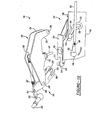
- convertible roof system 21 further includes a latching system 100 adapted for releasably securing front roof panel 23 to front header panel 41 and, additionally, front roof panel 23 to rear roof panel 25.
- Latching system 100 generally includes a drive mechanism 102 centrally disposed within front header panel 41, a pair of header latch assemblies 104 disposed along outboard portions of front header panel 41, and a pair of panel-to-panel latch assemblies 106 disposed along the outboard interface of front roof panel 23 and rear roof panel 25 .
- the pair of header latch assemblies 104 and the pair of panel-to-panel latch assemblies 106 are provided in mirrored symmetry and, thus, in interest the brevity, only one header latch assembly and panel-to-panel latch assembly will be discussed in detail herein.
- Drive mechanism 102 is illustrated in accordance with the principles of the present invention.
- Drive mechanism 102 generally includes a drive motor 108, which is operably coupled to a controller 110 via a line 112. Controller 110 provides a control signal to drive motor 108 to produce a rotary output from drive motor 108 in response to a predetermined condition and/or a user's actuation of a control switch.
- Drive motor 108 is operably coupled to a drive plate 114 via a gear interface 116.
- gear interface 116 may include any one of a number of drive transmission systems, such as a worm gear system, planetary gear system, and the like.
- drive motor 108 is coupled to a housing 118, which is in turn coupled to front header panel 41.
- drive plate 114 is rotatably coupled on an opposing side of housing 118 to be easily coupled to the header latch drive rods 120.
- Drive plate 114 is adapted to be rotated about its central axis 122 through a predetermined angular path.
- drive plate 114 may include at least one stop member 124 extending therefrom that is adapted to engage a corresponding physical stop 126 extending from housing 118.
- drive motor 108 and drive plate 114 are adapted to cooperate to drive header latch drive rods 120.
- actuation of drive motor 108 by controller 110 produces an oscillating rotating motion in drive plate 114.
- This oscillating rotating motion is transferred to each of the header latch drive rods 120 through a pivoting connection 128. That is, as drive plate 114 rotates from side to side, this rotating motion is converted into a linear motion through pivoting connection 128 as indicated by the arrows.
- header latch assembly 104 generally includes a striker assembly 130 and a retaining assembly 132.
- Striker assembly 130 generally includes a pair of spaced apart plates 134 and 136. Plates 134 and 136 are generally planar and L-shaped and include a striker member 138 extending therebetween.
- Header latch assembly 104 further includes a switch actuator 140 extending from a bridge portion 140 formed between plates 134 and 136.
- retaining assembly 132 generally includes a mounting housing 144, which is fixedly coupled to front panel header 41 via fasteners extending through mounting holes 146.
- retaining assembly 130 includes an input stud 148.
- Input stud 148 is coupled to an end of header latch drive rod 120 through a connector 150.
- input stud 148 is a ball stud that is adjustably coupled to threaded connector 150.
- Input stud 148 is moved in response to linear motion of header latch drive rod 120 through a path that generally corresponds to arcuate opening 152.
- Input stud 148 is fixedly coupled to a first linkage 154 at pivot 156.
- First linkage 154 is further pivotally coupled to mounting housing 144 at opposing pivot 158.
- First linkage 154 is still further pivotally coupled to second linkage 160 at pivot 156.
- An opposing end of second linkage 160 is further pivotally coupled to a midpoint pivot 162 of a third linkage 164.
- Third linkage 164 is pivotally coupled at one end to mounting housing 144 at pivot 166 and at an opposing end to a retaining member 168 at cam 170.
- Cam 179 includes a cam pin 172, a first cam slot 174, and a second cam slot 176.
- Cam pin 172 is fixedly coupled through an end of retaining member 168.
- a first end of cam pin 172 cammingly engages first cam slot 174.
- a second end of cam pin 172 cammingly engages second cam slot 176 formed in housing 144.
- Second cam slot 176 is generally angular shaped.
- Retaining member 168 is generally hook-shaped with a head 178.
- Retaining member 168 further includes a third cam slot 180 formed in the body thereof.
- Third cam slot 180 is adapted to cooperate with a second cam pin 182, which is fixedly coupled to mounting housing 144.
- Head 178 of retaining member 168 is adapted to engage and retain striker member 138 of striker assembly 130 to engage and retaining front roof panel 23 relative to front header panel 41.
- switch actuator 140 of striker assembly 130 is adapted to be received within a tapered aperture 184 to actuate a closure switch 186.
- Closure switch 186 is an electrical switch that is coupled to controller 110 or other logic device via a line 188.
- Closure switch 186 includes a movable prong 191, which is adapted to rotate in response to contact from switch actuator 140.
- Tapered aperture 184 is shaped to promote the alignment of switch actuator 140 relative to closure switch 186.
- header latch assembly 104 is actuated to provide a positive and reliable connection between front roof panel 23 and front header panel 41.
- controller 110 outputs a control signal to drive motor 108 in response to actuation of an interior occupant switch and/or closure switch 186.
- Drive motor 108 thus drives gear interface 116 to rotate drive plate to 114.
- Rotation of drive plate 114 pivots header latch drive rods 120 to produce a linear movement along header latch drive rod 120.
- header latch drive rods 120 produce a pulling force at the end thereof.
- header latch drive rods 120 produce a pushing force at the end thereof.
- second slot 176 generally includes a first arcuate section 190 and a second arcuate section 192. Movement of cam pin 172 and thus retaining member 168 through first arcuate section 190 of second slot 176 causes retaining member 168 to rotate in a generally circular direction as seen in FIGS. 11 and 12. However, movement of cam pin 172 through second arcuate section 192 of second slot 176 causes retaining member 168 to now moved in a generally linear direction as seen in FIG. 13. This final linear movement aids in pulling front roof panel 23 straight toward front header panel 41 to affect a reliable seal therebetween. Following this final linear movement, front roof panel 23 is now fixedly and reliably secured to front header panel 41. Unlocking of header latch assembly 104 is achieved through a reverse operation.
- Panel-to-panel latch assembly 106 generally includes a roller assembly 200 and a hook assembly 202.
- roller assembly 200 generally includes a crank 204 that is pivotally coupled between plates 134 and 136 of striker assembly 130 at pivot 206.
- Crank 204 includes a bifurcated end portion 208 and a roller portion 210.
- roller portion 210 is adapted to engage a roller surface 212 formed along a face surface 214 of mounting housing 144. That is, roller surface 212 generally provides a flat and uniform surface upon which roller portion 210 can roll (see FIGS. 12 and 13).
- bifurcated end portion 208 is preferably sized to fit within a corresponding bifurcated end 216 of roller surface 212. Bifurcated end portion 208 is adapted to engage a pin 218, which extends between bifurcated ends 216. More particularly, bifurcated end portion 208 includes an elongated finger 220, which extends along one side of pin 218. During an unlocking operation, elongated finger 220 engage pin 208 and ensures that crank 204 begins rotating in a counterclockwise direction as viewed in FIGS. 11-13.
- Roller assembly 200 further includes an extension spring 222 extending between in aperture 224 formed in crank 204 and a mounting post 225.
- Mounting post 227 is fixedly coupled between plates 134 and 136.
- Extension spring 222 biases crank 204 in a counterclockwise direction as seen in FIGS. 11-13.
- Crank 204 is pivotally coupled to a panel-to-panel latch drive rod 226 at pivot 228.
- panel-to-panel latch drive rod 226 is further pivotally coupled to a latch member 230 of hook assembly 202.
- a latch member 230 is pivotally mounted to a bracket 232 at pivot 234, which is fixed to front roof panel 23.
- Latch member 230 is generally U-shaped such that one leg of the U supports the pivot connection between panel-to-panel latch drive rod 226 and latch member 230. The other leg of the U supports pivot 234 and a hook portion 236.
- Hook portion 236 of latch member 230 is adapted to engage a connector 238 to define a locking engagement.
- Connector 238 is preferably a V-shaped connector when viewed in cross-section.
- Connector 238 is mounted to a bracket 240, which is fixed to rear roof panel 25.
- Hook assembly 202 further includes an extension spring 242, which extends between a mounting post 244 extending from bracket 232 and an aperture 246 formed in latch member 230. Extension spring 242 biases latch member 230 in a counterclockwise direction as seen in FIGS. 14 and 15. Accordingly, extension spring 242 cooperates with extension spring 222 to bias panel-to-panel latch assembly 106 into an unlatched position.
- panel-to-panel latch assembly 106 is actuated to provide a positive and reliable connection between front roof panel 23 and to rear roof panel 25. It should be appreciated that the latching and unlatching of panel-to-panel latch assembly 106 is dependent upon the engagement of front roof panel 23 with front header panel 41. More particularly, as top stack mechanism 27 drives front roof panel 23 toward front header panel 41, roller 210 engages roller surface 212 on face surface 214. Further actuation of front roof panel 23 toward front header panel 41 causes roller 210 to roll along roller surface 212, thereby pivoting crank 204 in a clockwise direction about pivot 206 and against the biasing force of extension spring 222, as seen in FIGS. 11-13. Such rotation of crank 204 about pivot 206 causes a forward linear movement of panel-to-panel latch drive rod 226.
- top stack mechanism 27 further drives front roof panel 23 and rear roof panel 25 to a closed position
- connector 238 travels to a position generally adjacent latch member 230.
- the forward linear movement of panel-to-panel latch drive rod 226 pulls upon latch member 230 to rotate latch member 230 about pivot 234 against the biasing force of extension spring 242.
- This rotation of latch member 230 causes hook portion 236 to engage connector 238, thereby fixedly coupling front roof panel 23 and rear roof panel 25.
- finger 220 of crank 204 is adapted to engage pin 218 to ensure that crank 204 is forced to rotated immediately into a counterclockwise direction, while extension springs 222 and 242 further encourage this motion, so as to ensure the proper unlatching of roller assembly 202.
Landscapes
- Engineering & Computer Science (AREA)
- Mechanical Engineering (AREA)
- Lock And Its Accessories (AREA)
- Body Structure For Vehicles (AREA)
Abstract
Description
Claims (21)
- A convertible roof system for an automobile, said convertible roof system comprising:a first hardtop roof panel movable between a closed position and an opened position;at least a second hardtop roof panel movable between a closed position and an opened position; anda latching system operable to directly couple said first hardtop roof panel and said second hardtop roof panel together in response to movement of said first hardtop roof panel from said opened position to said closed position.
- A convertible roof system as claimed in Claim 1, wherein said latching system comprises:a connector coupled to said second hardtop roof panel; anda latch member pivotally coupled to said first hardtop roof panel, said latch member being moveable to engage said connector thereby directly coupling said first hardtop roof panel and said second hardtop roof panel.
- A convertible roof system as claimed in claim 2, further comprising:a crank member operable to move between a first position and a second position when said first hardtop roof panel is moved into said closed position; anda drive member operably coupled with said crank member and said latch member such that as said crank member moves from said first position to said second position, said drive member drives said latch member into engagement with said connector thereby directly coupling said first hardtop roof panel and said second hardtop roof panel.
- A convertible roof system as claimed in Claim 3, wherein said crank member includes a roller member coupled thereto, said roller member engageable with a roller surface of a header of the automobile to cause said crank member to move from said first position to said second position as first hardtop roof panel is positioned in said closed position.
- A convertible roof system as claimed in any one of claims 2 to 4, wherein said latch member is biased in a disengaged position from said connector.
- A convertible roof system as claimed in any one of claims 2 to 5, wherein said latch member includes a hook portion engageable with said connector.
- A convertible roof system for an automobile, said convertible roof system comprising:a first hardtop roof panel movable between a closed position and an opened position;an actuator device mountable on the fixed body structure;a fixed member on the automobile;a drive rod operably coupled to said actuator device, said drive rod being driven in response to movement of said actuator device;a first linkage pivotally coupled to said drive rod and said fixed member, said first linkage being moveable with said drive rod;a second linkage pivotally coupled to said first linkage;a third linkage pivotally coupled to said fixed member and said second linkage, said third linkage being moveable in response to said second linkage; anda retaining member pivotally coupled to said third linkage, said retaining member further being pivotally coupled to said fixed member through a lost motion coupling, said retaining member being engageable with a striker assembly formed on said first hardtop roof panel to retain said first hardtop roof panel in said closed position.
- A convertible roof system as claimed in Claim 7, further comprising:a second hardtop roof panel movable between a closed position and an opened position; anda latching system operable to directly couple said first hardtop roof panel and said second hardtop roof panel together in response to movement of said first hardtop roof panel from said opened position to said closed position.
- A convertible roof system as claimed in Claim 8 wherein said latching system comprises:a connector coupled to said second hardtop roof panel; anda latch member pivotally coupled to said first hardtop roof panel, said latch member being moveable to engage said connector thereby directly coupling said first hardtop roof panel and said second hardtop roof panel.
- A convertible roof system as claimed in Claim 9, further comprising:a crank member pivotally coupled to said striker assembly, said crank member being operable to move between a first position and a second position as said crank member contacts said fixed member; anda drive member operably coupled with said crank member and said latch member such that as said crank member moves from said first position to said second position, said drive member drives said latch member into engagement with said connector.
- A convertible roof system as claimed in Claim 10, wherein said crank member includes a roller member coupled thereto, said roller member engageable with a roller surface on said fixed member to cause said crank member to move from said first position to said second position as first hardtop roof panel is positioned in said closed position.
- A convertible roof system as claimed in any one of claims 9 to 11, wherein said latch member is biased in a second position disengaged from said connector.
- A convertible roof system as claimed in any one of Claims 7 to 12, wherein said retaining member being pivotally coupled to said third linkage includes a cam pin extending from said retaining member, said cam pin operably engaging a first slot formed in said third linkage and a second slot formed in said fixed member.
- A convertible roof system as claimed in Claim 13, wherein said second slot is generally angular shaped.
- A convertible roof system as claimed in Claim 13 or Claim 14, wherein said latch member includes a hook portion engageable with said connector.
- A convertible roof system as claimed in any one of the preceding Claims, wherein said actuator device is a motorized actuator.
- A convertible roof system as claimed in any one of Claims 7 to 16, further comprising:a pin member formed on said striker assembly; anda switch member mounted on said fixed member, said switch member being operable to output a signal when said pin member engages said switch member once said first hardtop roof panel is in said closed position.
- A method of actuating a convertible roof system of an automotive vehicle, said convertible roof system having a first hardtop roof panel having a crank member pivotally coupled thereto, a second hardtop roof panel, a top stack mechanism supporting the first and second hardtop roof panels, and a latching system for coupling the first hardtop roof panel to the second hardtop roof panel, said crank member being pivotally coupled to the latching system, said method comprising:actuating said top stack mechanism to move said first hardtop roof panel and said second hardtop roof panel to a closed position such that said crank member pivots in response to contact of said crank member with a header support of the automotive vehicle;driving said latching system by said pivoting of said crank member; andcoupling said first hardtop roof panel and said second hardtop roof panel together.
- A method of actuating a convertible roof system of an automotive vehicle, said convertible roof system having a first hardtop roof panel, a striker assembly coupled to said first hardtop roof panel, and a fixed member coupled to the automotive vehicle, said method comprising:driving an actuator device coupled to a drive rod, said drive rod driving a first linkage pivotally coupled to said housing, said first linkage driving a second linkage, said second linkage driving a third linkage, said third linkage driving a retaining member via a lost motion cam assembly; andengaging and retaining said striker assembly of said first hardtop roof panel with said retaining member.
- The method according to Claim 19, further comprising:providing a second hardtop roof panel;providing a latching system having a crank member pivotally coupled to said striker assembly, a connector coupled to said second hardtop roof panel, a latch member pivotally coupled to said first hardtop roof panel, and a drive member interconnecting said crank member and said latch member; andpivoting said crank member in response to said step of engaging and retaining said striker assembly of said first hardtop roof panel with said retaining member;driving said drive member by said pivoting of said crank member;coupling said latch member with said connector to retain said first hardtop roof panel with said second hardtop roof panel.
- The method according to Claim 19 or Claim 20, further comprising:biasing said latch member disengaged from said connector.
Applications Claiming Priority (4)
| Application Number | Priority Date | Filing Date | Title |
|---|---|---|---|
| US628763 | 1996-04-05 | ||
| US40370102P | 2002-08-15 | 2002-08-15 | |
| US403701P | 2002-08-15 | ||
| US10/628,763 US6837535B2 (en) | 2002-08-15 | 2003-07-28 | Convertible roof system |
Publications (3)
| Publication Number | Publication Date |
|---|---|
| EP1389547A2 true EP1389547A2 (en) | 2004-02-18 |
| EP1389547A3 EP1389547A3 (en) | 2004-04-28 |
| EP1389547B1 EP1389547B1 (en) | 2007-04-18 |
Family
ID=30773140
Family Applications (1)
| Application Number | Title | Priority Date | Filing Date |
|---|---|---|---|
| EP03255028A Expired - Lifetime EP1389547B1 (en) | 2002-08-15 | 2003-08-13 | Convertible roof system |
Country Status (3)
| Country | Link |
|---|---|
| US (1) | US6837535B2 (en) |
| EP (1) | EP1389547B1 (en) |
| DE (1) | DE60313256T2 (en) |
Cited By (1)
| Publication number | Priority date | Publication date | Assignee | Title |
|---|---|---|---|---|
| FR2873146A1 (en) * | 2004-07-13 | 2006-01-20 | Oxford Automotive Mecanismes E | Movable body component e.g. sun roof, locking and unlocking device for vehicle, has two locks with elastic stops compressed during continuation of cam rotation to couple sliding sun roof and crosspiece of windshield bay in locking position |
Families Citing this family (16)
| Publication number | Priority date | Publication date | Assignee | Title |
|---|---|---|---|---|
| US6953217B2 (en) * | 2000-06-23 | 2005-10-11 | Cts Fahrzeug - Dachsysteme Gmbh | Locking arrangement for a movable hardtop vehicle roof |
| DE10300882B4 (en) * | 2003-01-13 | 2005-07-21 | Dr.Ing.H.C. F. Porsche Ag | Cover of a vehicle |
| JP4937897B2 (en) * | 2004-02-27 | 2012-05-23 | ツェーテーエス ファーツォイク ダッハジステーム ゲーエムベーハー | Latch system for convertible top |
| US6957842B1 (en) * | 2004-04-30 | 2005-10-25 | Asc Incorporated | Convertible roof bow tensioning apparatus |
| US7104587B2 (en) * | 2004-04-30 | 2006-09-12 | Asc Incorporated | Joint locking device for a convertible roof system |
| FR2870789B1 (en) * | 2004-05-25 | 2008-09-19 | France Design Sa | REPLIABLE ROOF WITH LATCHING SYSTEM FOR A CONVERTIBLE VEHICLE |
| US7243983B2 (en) * | 2005-02-23 | 2007-07-17 | Asc Incorporated | Retractable pillar for convertible vehicle |
| DE102005052063A1 (en) * | 2005-10-28 | 2007-05-03 | Webasto Ag | Locking device of a convertible top compartment cover of a convertible |
| ATE453529T1 (en) * | 2006-04-21 | 2010-01-15 | Heuliez | DEVICE FOR LOCKING A RETRACTABLE ROOF AND VEHICLE EQUIPPED WITH SUCH A SYSTEM |
| CN201291741Y (en) * | 2008-09-24 | 2009-08-19 | 比亚迪股份有限公司 | Vehicle roof turning device and vehicle having the device |
| JP5177536B2 (en) * | 2008-09-25 | 2013-04-03 | アイシン精機株式会社 | Open roof opening and closing device |
| DE102009010721A1 (en) * | 2009-02-27 | 2010-09-02 | Magna Car Top Systems Gmbh | Locking device for a moving roof of a passenger car |
| DE102012216427A1 (en) * | 2012-09-14 | 2014-05-15 | Magna Car Top Systems Gmbh | Kinematics for a flap |
| DE102015100840B4 (en) * | 2015-01-21 | 2019-02-14 | Webasto-Edscha Cabrio GmbH | Rear window module and convertible vehicle with rear window module |
| DE102019101992A1 (en) * | 2018-01-29 | 2019-08-01 | Magna Closures Inc. | Actuated active pedestrian safety interlock mechanism |
| JP7064457B2 (en) * | 2019-02-19 | 2022-05-10 | 本田技研工業株式会社 | Vehicle pop-up hood device |
Family Cites Families (111)
| Publication number | Priority date | Publication date | Assignee | Title |
|---|---|---|---|---|
| US2935350A (en) * | 1957-12-20 | 1960-05-03 | Carl J Bestrom | Tailgate latch |
| US4415189A (en) * | 1981-03-05 | 1983-11-15 | Falk, Kastelic, Heartwell, Inc. | Lock system for removable automobile roofs |
| US4523785A (en) * | 1981-12-23 | 1985-06-18 | Cars & Concepts, Inc. | Latch mechanism for hinged panels |
| US4466644A (en) * | 1982-01-18 | 1984-08-21 | Levan Specialty Co., Inc. | Multi-positioning latch assembly |
| US4441345A (en) * | 1982-01-19 | 1984-04-10 | Guarr David A | Lock device for vehicle hoods |
| DE3201895A1 (en) * | 1982-01-22 | 1983-08-04 | Dr.Ing.H.C. F. Porsche Ag, 7000 Stuttgart | FOLDING COVER FOR A MOTOR VEHICLE, IN PARTICULAR PERSONAL VEHICLES |
| US4540215A (en) * | 1983-03-16 | 1985-09-10 | Swearingen Ralph M | Lock system for removable automobile roof panel |
| US4529243A (en) * | 1983-04-29 | 1985-07-16 | Asc Incorporated | Vehicle with a convertible top |
| US4537440A (en) * | 1983-04-29 | 1985-08-27 | Asc Incorporated | Vehicle with a convertible top |
| US4600233A (en) * | 1985-01-22 | 1986-07-15 | Boydston Robert W | Mini-tonneau cover apparatus for rear compartment of convertible vehicle |
| US4687247A (en) * | 1985-05-13 | 1987-08-18 | Muscat Peter P | Powered tonneau cover for convertible automobiles |
| JPH04985Y2 (en) * | 1985-08-16 | 1992-01-14 | ||
| US4712828A (en) | 1985-11-07 | 1987-12-15 | California Auto Trends | Convertible top apparatus for midengine automobiles |
| FR2605039B1 (en) * | 1986-10-10 | 1990-07-13 | Lunke & Sohn Gmbh | LOCK FOR VEHICLES, ASSISTED BY AN ENERGY SOURCE. |
| USRE33790E (en) | 1986-10-21 | 1992-01-07 | Demountable pick-up truck tonneau cover | |
| DE3725431A1 (en) * | 1987-07-31 | 1989-02-09 | Porsche Ag | LOCK FOR A TOW OF A VEHICLE, ESPECIALLY A PASSENGER CAR |
| DE3731068A1 (en) * | 1987-09-16 | 1989-03-30 | Porsche Ag | LOCKING DEVICE FOR A CANOPY |
| US5186516A (en) * | 1987-09-24 | 1993-02-16 | Asc Incorporated | Power latch system |
| US4819983A (en) * | 1987-09-24 | 1989-04-11 | Asc Incorporated | Power latch system |
| US4783113A (en) * | 1987-11-03 | 1988-11-08 | Cars & Concepts, Inc. | Vehicle convertible top boot assembly having storage compartment |
| US4830425A (en) * | 1988-01-04 | 1989-05-16 | Muscat Peter P | Latching system for a convertible top |
| DE3830393C1 (en) | 1988-09-07 | 1989-08-24 | Daimler-Benz Aktiengesellschaft, 7000 Stuttgart, De | |
| US5052640A (en) * | 1989-08-29 | 1991-10-01 | Hughes Aircraft Company | Spacecraft design enabling the flat packing of multiple spacecraft in the launch vehicle |
| JPH0790695B2 (en) * | 1989-09-26 | 1995-10-04 | 株式会社大井製作所 | Roof door opening and closing device |
| US5085483A (en) * | 1989-11-17 | 1992-02-04 | Asc Incorporated | Convertible top latching mechanism |
| DE3940839C1 (en) * | 1989-12-11 | 1991-01-31 | Dr.Ing.H.C. F. Porsche Ag, 7000 Stuttgart, De | |
| US5046767A (en) * | 1989-12-13 | 1991-09-10 | Jubbu Designer's Inc. | Convertible top latching mechanism |
| EP0492006B1 (en) | 1990-12-22 | 1994-04-20 | Design + Technik Gmbh | Lowering device of the free edge of vehicle soft top or similar |
| US5154479A (en) * | 1991-02-28 | 1992-10-13 | Wickes Manufacturing Company | Power header latch for convertible top |
| DE4230985C2 (en) * | 1991-09-17 | 1996-07-11 | Mitsubishi Motors Corp | Trunk lock |
| IT1259541B (en) * | 1992-04-14 | 1996-03-20 | Roltra Morse Spa | HOOKING AND CLOSING DEVICE FOR OPENING ROOFS OF VEHICLES |
| DE4217636C1 (en) * | 1992-05-28 | 1993-05-06 | Mercedes-Benz Aktiengesellschaft, 7000 Stuttgart, De | |
| US5301987A (en) * | 1992-09-04 | 1994-04-12 | Asc Incorporated | Convertible top stack latch |
| US5624149A (en) * | 1992-09-04 | 1997-04-29 | Asc Incorporated | Apparatus and method for securing a convertible roof to an automotive vehicle |
| US5284378A (en) * | 1992-11-16 | 1994-02-08 | Wickes Manufacturing Company | Self-storing convertible top latch system |
| DE9302292U1 (en) * | 1993-02-17 | 1994-06-16 | Wilhelm Karmann GmbH, 49084 Osnabrück | Locking device for convertible tops |
| US5322336A (en) * | 1993-04-19 | 1994-06-21 | Mark Isler | Hinged tonneau cover for a pick-up truck bed |
| NL9302107A (en) * | 1993-12-03 | 1995-07-03 | Applied Power Inc | Device for securing a roof of a vehicle, in particular a convertible folding roof, and vehicle provided with such a device. |
| US5490709A (en) * | 1993-12-07 | 1996-02-13 | Asc Incorporated | Hinge for a folding roof in a convertible automotive vehicle |
| US5785375A (en) * | 1993-12-29 | 1998-07-28 | Asc Incorporated | Retractable hard-top for an automotive vehicle |
| US5743587A (en) * | 1993-12-29 | 1998-04-28 | Asc Incorporated | Apparatus for use in an automotive vehicle having a convertible roof system |
| DE4415969C2 (en) | 1994-05-08 | 2002-05-16 | Scharwaechter Gmbh Co Kg | Closure drive for a folding roof of a motor vehicle |
| DE4423834C1 (en) * | 1994-07-07 | 1995-11-09 | Daimler Benz Ag | Drive arrangement for a retractable folding roof |
| DE4435222C1 (en) * | 1994-09-30 | 1995-11-02 | Webasto Karosseriesysteme | Roof for convertible car |
| US5582454A (en) | 1994-10-14 | 1996-12-10 | Mascotech Automotive Systems Group, Inc. | Spring-biased latching pin for a convertible top |
| US5755467A (en) * | 1995-01-31 | 1998-05-26 | Asc Incorporated | Latching and switch operating system for a convertible roof |
| DE19507431C1 (en) | 1995-03-03 | 1996-08-01 | Daimler Benz Ag | Hardtop vehicle |
| NL1001283C2 (en) * | 1995-09-26 | 1997-03-28 | Inalfa Ind Bv | Folding roof for a vehicle. |
| DE19538738C1 (en) * | 1995-10-18 | 1997-01-23 | Porsche Ag | Lid for wall slot over roof bearing, esp. on open vehicle |
| US5620226A (en) * | 1995-12-07 | 1997-04-15 | Dura Convertible Systems, Inc. | Simplified automated top operator |
| US5722704A (en) * | 1996-04-23 | 1998-03-03 | Reflectolite Products, Inc. | Multi-point door lock |
| DE19623036A1 (en) * | 1996-06-08 | 1997-12-11 | Karmann Gmbh W | Vehicle, in particular with a retractable roof |
| DE19634510C1 (en) * | 1996-08-27 | 1998-01-22 | Daimler Benz Ag | Roof structure for a motor vehicle, especially for a passenger car |
| DE19634511C1 (en) * | 1996-08-27 | 1998-01-22 | Daimler Benz Ag | Movable roof construction for an open passenger car |
| DE19637005C1 (en) * | 1996-09-12 | 1997-12-18 | Daimler Benz Ag | Plate covering for front area of frame opening of hood box |
| US5953710A (en) * | 1996-10-09 | 1999-09-14 | Fleming; Stephen S. | Children's credit or debit card system |
| NL1004575C2 (en) * | 1996-11-20 | 1998-05-25 | Inalfa Ind Bv | Control device for an open roof construction, as well as an open roof construction. |
| DE29620468U1 (en) | 1996-11-23 | 1998-04-02 | Wilhelm Karmann GmbH, 49084 Osnabrück | Cabriolet vehicle |
| DE29620492U1 (en) * | 1996-11-25 | 1998-03-26 | Wilhelm Karmann GmbH, 49084 Osnabrück | Cabriolet vehicle |
| DE19650402C2 (en) * | 1996-12-05 | 2002-02-07 | Porsche Ag | Convertible top compartment lid for a motor vehicle |
| DE19706398A1 (en) * | 1997-02-19 | 1998-08-20 | Daimler Benz Ag | Hard top for a convertible |
| JP3849219B2 (en) * | 1997-03-31 | 2006-11-22 | マツダ株式会社 | Open car wind entanglement prevention device |
| DE19721229B4 (en) | 1997-05-21 | 2005-05-04 | Dr.Ing.H.C. F. Porsche Ag | Closure for a hood of a vehicle, in particular a passenger car |
| FI102468B (en) * | 1997-06-16 | 1998-12-15 | Valmet Automotive Oy | Open car with a hard roof construction that can be opened |
| US6042174A (en) * | 1997-08-22 | 2000-03-28 | Asc Incorporated | Latching and control apparatus for an automotive vehicle convertible roof |
| DE19741134C1 (en) * | 1997-09-12 | 1998-10-15 | Rockwell International Gmbh | Sun roof of motor vehicle |
| EP0928711B1 (en) * | 1998-01-08 | 2001-05-30 | Edscha Cabrio-Dachsysteme GmbH | Linkage for soft top compartment lid |
| US6109680A (en) * | 1998-02-13 | 2000-08-29 | John Donovan Enterprises-Fl., Inc. | Covering system |
| DE19807490C1 (en) * | 1998-02-21 | 1999-09-02 | Daimler Chrysler Ag | Roof construction for motor vehicle |
| DE19809061A1 (en) * | 1998-03-04 | 1999-09-09 | Porsche Ag | Method for controlling a roof to be opened with a locking device |
| US6422462B1 (en) * | 1998-03-30 | 2002-07-23 | Morris E. Cohen | Apparatus and methods for improved credit cards and credit card transactions |
| FR2777240B1 (en) | 1998-04-09 | 2000-06-09 | France Design | REAR TRUNK FOR DISCOVERABLE VEHICLE WITH FOLDABLE ROOF, COMPRISING A REAR TRUNK AND A REAR BEACH |
| US6048021A (en) * | 1998-04-25 | 2000-04-11 | Dura Convertible Systems | Convertible top mechanism with powered rear row |
| FR2778610B1 (en) * | 1998-05-12 | 2000-08-04 | France Design | FOLDABLE ROOF IN THREE ELEMENTS FOR DISCOVERABLE VEHICLE |
| US5998948A (en) | 1998-05-29 | 1999-12-07 | Acs Incorporated | Convertible roof actuation mechanism |
| EP1044838B1 (en) * | 1998-06-16 | 2001-12-05 | Dura Convertible Systems GmbH | Locking device for convertible top of motor vehicle |
| BR9911990A (en) * | 1998-06-24 | 2001-10-16 | Cardio Tech Inc | High pressure inflating system to trigger an inflatable cardiac assist device and transfer valve |
| DE19832868B4 (en) * | 1998-07-22 | 2004-03-11 | Dr.Ing.H.C. F. Porsche Ag | blocking element |
| DE19841103C1 (en) * | 1998-09-09 | 2000-03-16 | Daimler Chrysler Ag | Hard top road vehicle has front roof part and rear roof part provided with fixed rear plate, lateral main guides for movement of front and rear parts and side vehicle columns |
| US5954382A (en) * | 1998-12-08 | 1999-09-21 | Astro Cap Manufacturing West, Inc. | Pickup truck tailgate trimpiece |
| DE19910763C1 (en) * | 1999-03-11 | 2000-07-13 | Daimler Chrysler Ag | Motor vehicle boot lid operator comprizes strut tubes whose locking wedge is freed or engaged with receiver mounting by pulling respective bowden cable ties off hydraulic cylinder. |
| FR2791007B1 (en) * | 1999-03-16 | 2001-05-25 | France Design | FOLDABLE ROOF FOR DISCOVERABLE VEHICLE |
| DE19911537C1 (en) | 1999-03-16 | 2000-09-14 | Daimler Chrysler Ag | Device for driving a convertible top for a convertible vehicle |
| DE60002772T2 (en) | 1999-03-26 | 2004-08-19 | Cts Fahrzeug-Dachsysteme Gmbh | Swiveling cover for vehicles |
| US6290281B1 (en) * | 1999-05-26 | 2001-09-18 | Asc Incorporated | Power latch for an automotive vehicle convertible roof system |
| US6217104B1 (en) | 1999-06-16 | 2001-04-17 | Cts Fahrzeug Dachsysteme Gmbh | Retractable hard top module |
| DE19935739A1 (en) | 1999-07-29 | 2001-02-08 | Lunke Ventra Automotive Gmbh | Lock part for releasably connecting a vehicle roof to a body component |
| DE19935738C2 (en) | 1999-07-29 | 2001-05-23 | Lunke Ventra Automotive Gmbh | Closing and locking device for releasably connecting a vehicle roof to a body component |
| DE29913486U1 (en) * | 1999-08-03 | 2000-12-14 | Wilhelm Karmann GmbH, 49084 Osnabrück | Cabriolet vehicle |
| DE19941207C1 (en) * | 1999-08-30 | 2001-05-10 | Webasto Dachsysteme Gmbh | Drive device for a swivel component |
| DE19942428C2 (en) * | 1999-09-06 | 2001-11-22 | Webasto Vehicle Sys Int Gmbh | Convertible top |
| KR100316952B1 (en) * | 1999-09-13 | 2001-12-22 | 이계안 | Roof ventilators for closed vehicle |
| US6309005B1 (en) * | 1999-10-12 | 2001-10-30 | Delphi Technologies, Inc. | Hinge assembly for tonneau cover |
| DE59903413D1 (en) * | 1999-10-12 | 2002-12-19 | Dura Convertible Systems Gmbh | Retractable hardtop for motor vehicles and motor vehicles with a hardtop |
| JP4292354B2 (en) * | 1999-10-19 | 2009-07-08 | アイシン精機株式会社 | Package tray for vehicles |
| US6419308B1 (en) * | 1999-10-29 | 2002-07-16 | Asc Incorporated | Movable roof system for an automotive vehicle |
| US6227604B1 (en) * | 1999-11-01 | 2001-05-08 | Rkr Manufacturing, Inc. | Auto top conversion frame assembly |
| US6361086B1 (en) * | 1999-11-12 | 2002-03-26 | Daimlerchrysler Corporation | Mechanical latch |
| DE19960022C1 (en) * | 1999-12-13 | 2001-06-07 | Edscha Cabrio Verdecksys Gmbh | Safety system for the release lock at the roof of a convertible automobile has a signal generator which blocks the hand grip movement on an accidental opening action |
| DE19963149B4 (en) * | 1999-12-24 | 2004-11-04 | Wilhelm Karmann Gmbh | Cabriolet vehicle with a fold-out roof |
| US6409247B1 (en) * | 1999-12-24 | 2002-06-25 | Wilhelm Karmann Gmbh | Convertible vehicle with an at least partially flexible roof and at least one cross-connecting support |
| JP4453147B2 (en) * | 2000-02-25 | 2010-04-21 | アイシン精機株式会社 | VEHICLE ROOF LOCK DEVICE AND ITS OPERATION CONTROL DEVICE |
| FI110418B (en) | 2000-05-05 | 2003-01-31 | Valmet Automotive Oy | Convertible |
| JP2001342509A (en) * | 2000-06-02 | 2001-12-14 | Kobe Steel Ltd | Method and apparatus for producing metallic iron |
| US6254165B1 (en) * | 2000-08-16 | 2001-07-03 | Cts Fahrzeug Dachsysteme Gmbh | Tonneau cover and decklid linkage and drive system |
| US6318793B1 (en) | 2000-12-29 | 2001-11-20 | General Motors Corporation | Two piece retractable hard-top roof for an automobile |
| US6347828B1 (en) | 2000-12-29 | 2002-02-19 | General Motors Corporation | Actuation mechanism for a two piece retractable hard-top roof for an automobile |
| FR2820692B1 (en) | 2001-02-14 | 2003-04-04 | France Design | RETRACTABLE ROOF WITH LOCKING DEVICE IMPROVING THE RIGIDITY OF THE ROOF |
| DE10139354A1 (en) * | 2001-08-17 | 2003-03-13 | Karmann Gmbh W | Convertible car |
| DE10144515C2 (en) * | 2001-09-10 | 2003-08-07 | Cts Fahrzeug Dachsysteme Gmbh | Adjustable vehicle top |
| DE10218307B4 (en) * | 2002-04-24 | 2007-10-18 | Webasto Ag | Roof construction for a convertible |
-
2003
- 2003-07-28 US US10/628,763 patent/US6837535B2/en not_active Expired - Lifetime
- 2003-08-13 DE DE60313256T patent/DE60313256T2/en not_active Expired - Lifetime
- 2003-08-13 EP EP03255028A patent/EP1389547B1/en not_active Expired - Lifetime
Cited By (1)
| Publication number | Priority date | Publication date | Assignee | Title |
|---|---|---|---|---|
| FR2873146A1 (en) * | 2004-07-13 | 2006-01-20 | Oxford Automotive Mecanismes E | Movable body component e.g. sun roof, locking and unlocking device for vehicle, has two locks with elastic stops compressed during continuation of cam rotation to couple sliding sun roof and crosspiece of windshield bay in locking position |
Also Published As
| Publication number | Publication date |
|---|---|
| EP1389547B1 (en) | 2007-04-18 |
| US6837535B2 (en) | 2005-01-04 |
| EP1389547A3 (en) | 2004-04-28 |
| US20040032146A1 (en) | 2004-02-19 |
| DE60313256T2 (en) | 2008-02-28 |
| DE60313256D1 (en) | 2007-05-31 |
Similar Documents
| Publication | Publication Date | Title |
|---|---|---|
| EP1389547B1 (en) | Convertible roof system | |
| US7488029B2 (en) | Independently opening doors for an automotive door opening | |
| US6183039B1 (en) | Pivot and slide door system | |
| US5678881A (en) | Apparatus and method for securing a convertible roof to an automotive vehicle | |
| CN105378200B (en) | The double motor device with bolt lock mechanism is drawn applied to dynamical system | |
| US7341303B2 (en) | Joint locking device for a convertible roof system | |
| EP1449698B1 (en) | Vehicle open roof apparatus | |
| US5325585A (en) | Method for the assembly of a sun roof of an automotive vehicle | |
| US20040094988A1 (en) | Convertible top latch | |
| US7140666B2 (en) | Latch for an automobile vehicle having a convertible roof | |
| EP1842710B1 (en) | Retractable roof and vehicle therewith | |
| EP1389549B1 (en) | Convertible roof latch | |
| US7320495B2 (en) | Motor vehicle | |
| US6568495B1 (en) | Automotive vehicle hood system | |
| US4540215A (en) | Lock system for removable automobile roof panel | |
| US7093884B2 (en) | Bulkhead module for an automotive vehicle having a convertible roof | |
| US20080122248A1 (en) | Header latch assembly for convertible tops | |
| WO2021003566A1 (en) | Closure latch assembly with power cinch mechanism having anti-chucking function | |
| JP3153291B2 (en) | Car sunroof structure | |
| KR930006157B1 (en) | Automotive Roofing Systems | |
| JPH01233117A (en) | Car body structure for automobile |
Legal Events
| Date | Code | Title | Description |
|---|---|---|---|
| PUAI | Public reference made under article 153(3) epc to a published international application that has entered the european phase |
Free format text: ORIGINAL CODE: 0009012 |
|
| AK | Designated contracting states |
Kind code of ref document: A2 Designated state(s): AT BE BG CH CY CZ DE DK EE ES FI FR GB GR HU IE IT LI LU MC NL PT RO SE SI SK TR |
|
| AX | Request for extension of the european patent |
Extension state: AL LT LV MK |
|
| PUAL | Search report despatched |
Free format text: ORIGINAL CODE: 0009013 |
|
| AK | Designated contracting states |
Kind code of ref document: A3 Designated state(s): AT BE BG CH CY CZ DE DK EE ES FI FR GB GR HU IE IT LI LU MC NL PT RO SE SI SK TR |
|
| AX | Request for extension of the european patent |
Extension state: AL LT LV MK |
|
| 17P | Request for examination filed |
Effective date: 20040624 |
|
| 17Q | First examination report despatched |
Effective date: 20040730 |
|
| AKX | Designation fees paid |
Designated state(s): DE FR GB |
|
| GRAP | Despatch of communication of intention to grant a patent |
Free format text: ORIGINAL CODE: EPIDOSNIGR1 |
|
| GRAS | Grant fee paid |
Free format text: ORIGINAL CODE: EPIDOSNIGR3 |
|
| GRAA | (expected) grant |
Free format text: ORIGINAL CODE: 0009210 |
|
| AK | Designated contracting states |
Kind code of ref document: B1 Designated state(s): DE FR GB |
|
| REF | Corresponds to: |
Ref document number: 60313256 Country of ref document: DE Date of ref document: 20070531 Kind code of ref document: P |
|
| RAP2 | Party data changed (patent owner data changed or rights of a patent transferred) |
Owner name: SSR ROOFING SYSTEM, LLC |
|
| REG | Reference to a national code |
Ref country code: GB Ref legal event code: 732E |
|
| RAP2 | Party data changed (patent owner data changed or rights of a patent transferred) |
Owner name: ASC INCORPORATED Owner name: WILHELM KARMANN GMBH |
|
| ET | Fr: translation filed | ||
| RAP2 | Party data changed (patent owner data changed or rights of a patent transferred) |
Owner name: SPECIALTY VEHICLE ACQUISITION CORP. Owner name: WILHELM KARMANN GMBH |
|
| PGFP | Annual fee paid to national office [announced via postgrant information from national office to epo] |
Ref country code: GB Payment date: 20070809 Year of fee payment: 5 |
|
| PLBE | No opposition filed within time limit |
Free format text: ORIGINAL CODE: 0009261 |
|
| STAA | Information on the status of an ep patent application or granted ep patent |
Free format text: STATUS: NO OPPOSITION FILED WITHIN TIME LIMIT |
|
| 26N | No opposition filed |
Effective date: 20080121 |
|
| PGFP | Annual fee paid to national office [announced via postgrant information from national office to epo] |
Ref country code: FR Payment date: 20070808 Year of fee payment: 5 |
|
| REG | Reference to a national code |
Ref country code: FR Ref legal event code: TQ |
|
| GBPC | Gb: european patent ceased through non-payment of renewal fee |
Effective date: 20080813 |
|
| REG | Reference to a national code |
Ref country code: FR Ref legal event code: ST Effective date: 20090430 |
|
| PG25 | Lapsed in a contracting state [announced via postgrant information from national office to epo] |
Ref country code: FR Free format text: LAPSE BECAUSE OF NON-PAYMENT OF DUE FEES Effective date: 20080901 |
|
| PG25 | Lapsed in a contracting state [announced via postgrant information from national office to epo] |
Ref country code: GB Free format text: LAPSE BECAUSE OF NON-PAYMENT OF DUE FEES Effective date: 20080813 |
|
| REG | Reference to a national code |
Ref country code: DE Ref legal event code: R082 Ref document number: 60313256 Country of ref document: DE Representative=s name: KRONTHALER, SCHMIDT & COLL. PATENTANWALTSKANZL, DE Effective date: 20131128 Ref country code: DE Ref legal event code: R081 Ref document number: 60313256 Country of ref document: DE Owner name: VALMET AUTOMOTIVE OY, FI Free format text: FORMER OWNER: WILHELM KARMANN GMBH, 49084 OSNABRUECK, DE Effective date: 20131128 |
|
| PGFP | Annual fee paid to national office [announced via postgrant information from national office to epo] |
Ref country code: DE Payment date: 20140922 Year of fee payment: 12 |
|
| REG | Reference to a national code |
Ref country code: DE Ref legal event code: R119 Ref document number: 60313256 Country of ref document: DE |
|
| PG25 | Lapsed in a contracting state [announced via postgrant information from national office to epo] |
Ref country code: DE Free format text: LAPSE BECAUSE OF NON-PAYMENT OF DUE FEES Effective date: 20160301 |