EP1389542B1 - Heating, ventilation, and air conditioning system having improved air warm-up - Google Patents
Heating, ventilation, and air conditioning system having improved air warm-up Download PDFInfo
- Publication number
- EP1389542B1 EP1389542B1 EP03077393A EP03077393A EP1389542B1 EP 1389542 B1 EP1389542 B1 EP 1389542B1 EP 03077393 A EP03077393 A EP 03077393A EP 03077393 A EP03077393 A EP 03077393A EP 1389542 B1 EP1389542 B1 EP 1389542B1
- Authority
- EP
- European Patent Office
- Prior art keywords
- blower
- air
- dashboard
- vehicle
- passenger compartment
- Prior art date
- Legal status (The legal status is an assumption and is not a legal conclusion. Google has not performed a legal analysis and makes no representation as to the accuracy of the status listed.)
- Expired - Lifetime
Links
Images



Classifications
-
- B—PERFORMING OPERATIONS; TRANSPORTING
- B60—VEHICLES IN GENERAL
- B60H—ARRANGEMENTS OF HEATING, COOLING, VENTILATING OR OTHER AIR-TREATING DEVICES SPECIALLY ADAPTED FOR PASSENGER OR GOODS SPACES OF VEHICLES
- B60H1/00—Heating, cooling or ventilating devices
- B60H1/00642—Control systems or circuits; Control members or indication devices for heating, cooling or ventilating devices
- B60H1/00735—Control systems or circuits characterised by their input, i.e. by the detection, measurement or calculation of particular conditions, e.g. signal treatment, dynamic models
- B60H1/00785—Control systems or circuits characterised by their input, i.e. by the detection, measurement or calculation of particular conditions, e.g. signal treatment, dynamic models by the detection of humidity or frost
-
- B—PERFORMING OPERATIONS; TRANSPORTING
- B60—VEHICLES IN GENERAL
- B60H—ARRANGEMENTS OF HEATING, COOLING, VENTILATING OR OTHER AIR-TREATING DEVICES SPECIALLY ADAPTED FOR PASSENGER OR GOODS SPACES OF VEHICLES
- B60H1/00—Heating, cooling or ventilating devices
- B60H1/24—Ventilating devices where the heating or cooling is irrelevant
- B60H1/247—Disposition of several air-diffusers in a vehicle for ventilation-air circulation in a vehicle cabin
Definitions
- HVAC heating, ventilation, and air conditioning
- HVAC heating, ventilation, and air conditioning
- the blower has a first inlet duct for drawing air from outside the vehicle and a second inlet duct for drawing air from within the vehicle.
- the HVAC module has outlets for venting the air into the vehicle.
- German Patent Publication No DE3714771A1 to Bayerische Motoren Werke AG describes use of a defroster nozzle for the vehicle windscreen where the defroster nozzle also assumes the function of a recirculating air suction opening.
- This disclosure describes use of a single chamber having a valve located at its lower end in order to switch between intake and blow mode.
- HVAC system that continues to circulate air throughout the passenger compartment while in recirculation mode. It would also be advantageous to provide the HVAC system having an improved warm-up rate of air within the passenger compartment while operating in the recirculation mode. Further, it would be advantageous to provide an HVAC system that has improved airflow across a windshield of the vehicle to prevent fogging of the windshield.
- the subject invention provides a vehicle having a heating, ventilation, and air conditioning (HVAC) system being operable in a fresh air mode and a recirculation mode.
- the vehicle includes a passenger compartment having a front and a back and a dashboard located in the front of the passenger compartment.
- the HVAC system includes a blower in fluid communication with tne passenger compartment for circulating air from outside the vehicle into and through the passenger compartment in the fresh air mode and for recirculating air from within the passenger compartment in the recirculation mode.
- the HVAC system further includes a heating, ventilation, and air conditioning (HVAC) module in fluid communication with and downstream of the blower for warming and cooling the air to be circulated through the passenger compartment in both the fresh air mode and the recirculation mode.
- HVAC heating, ventilation, and air conditioning
- the system is characterized by an inlet duct in fluid communication with and upstream of the blower and located above the dashboard for drawing air from the passenger compartment above the dashboard and through the blower and the HVAC module in the recirculation mode where the inlet duct is divided into a first chamber for drawing air in through the defrost duct in the dashboard and a second chamber for venting air from the HVAC module out through the defrost duct.
- the inlet duct above the dashboard does not create a short circuit in the airflow within the passenger compartment during recirculation mode. By forcing the air to flow throughout the passenger compartment, the air has an improved warm up rate, which improves the level of the occupant's comfort.
- the inlet duct above the dashboard also improves the flow of air across a windshield of the vehicle to prevent fogging of the windshield.
- HVAC heating, ventilation, and air conditioning
- the HVAC system 10 is operable in a fresh air mode and a recirculation mode.
- the HVAC system 10 draws air from outside a vehicle 12 and vents the air into the vehicle 12 in the fresh air mode.
- the HVAC system 10 also draws air from within the vehicle 12 and recirculates the air back into the vehicle 12 in the recirculation mode. It is to be appreciated that HVAC systems may be able to simultaneously mix the fresh, ambient air and the recirculated air.
- the vehicle 12 includes a passenger compartment 14 having a front 16 and a back 18.
- a dashboard 20 is located in the front 16 of the passenger compartment 14.
- the vehicle 12 has an engine compartment 22 located at the front 16 of the vehicle 12.
- the terms "front” and “back” are intended to be very general, and the structures that define and delimit the front 16 and back 18 will, in any particular case, differ.
- the front 16 would be defined by those structures in front 16 of a front seat passenger or driver, such as a windshield, the dashboard 20, and the like.
- the back 18 would be defined by structures such as a shelf behind the back passengers and whatever structure separates the back seating from a trunk space 26.
- the passenger compartment 14 is bounded above by a roof structure 28 and below by a floor 30.
- front and back are intended here to be inclusive, rather than exclusive, and relate more to the air movement inside the passenger compartment 14, than to its structural features. That is, air will move generally from front 16 to back 18, in the fresh air mode, and will circulate back again generally from back 18 to front 16 in the recirculation mode.
- the HVAC system 10 includes a blower 32, shown in Figure 1, mounted in either the back of the engine compartment 22 or adjacent the dashboard 20, as is known in the art of HVAC systems.
- the blower 32 is in fluid communication with the passenger compartment 14 for circulating air from outside the vehicle 12 into and through the passenger compartment 14 in the fresh air mode and for recirculating air from within the passenger compartment 14 in the recirculation mode.
- the blower 32 will be described in more detail below.
- the HVAC system 10 further includes a heating, ventilation, and air conditioning (HVAC) module 34 in fluid communication with and downstream of the blower 32 for warming and cooling the air to be circulated through the passenger compartment 14 in both the fresh air mode and the recirculation mode.
- HVAC heating, ventilation, and air conditioning
- the HVAC module 34 includes an evaporator 36, a heater core 38, and a temperature door 40, as is known in the art.
- the temperature door 40 is moveable to select the amount of air that flows through the heater core 38, as understood by those skilled in the art.
- the HVAC module shown in Figure 1 is a dual zone HVAC module that allow the driver and the passenger to select different temperatures.
- the subject invention is equally applicable with a single zone HVAC module or a dual mode HVAC module as known by those skilled in the art.
- the HVAC module 34 has outlets for venting the air into the vehicle 12.
- One outlet is a defrost duct 42 located in fluid communication with and downstream of the HVAC module 34 and adapted to be located above the dashboard 20 for venting the air into the passenger compartment 14.
- the defrost ducts 42 vent air from the HVAC system 10 into the passenger compartment 14.
- the defrost ducts 42 are typically located just below the windshield on the dashboard 20 to prevent fogging of the windshield.
- a second outlet is a panel outlet 44 venting air out the front 16 of the dashboard 20, and a third outlet is a floor outlet 46 venting air out below the dashboard 20.
- the HVAC module 34 includes a first inlet duct 48 in fluid communication with and upstream of the blower 32 for drawing ambient air from outside of the passenger compartment 14 and through the blower 32 and the HVAC module 34 in the fresh air mode.
- the HVAC module 34 further includes a second inlet duct 50 in fluid communication with and upstream of the blower 32 and adapted to be located below the dashboard 20 for drawing air from below the dashboard 20 in the passenger compartment 14 and through the blower 32 and the HVAC module 34 in the recirculation mode.
- Inlet ducts channel the flow of the air from either outside or inside the vehicle to the blower, as is known to those skilled in the art.
- the inlet ducts may be rectangular or circular depending upon the amount of space where the module is located in either the engine compartment or the passenger compartment.
- the blower 32 includes a first blower port 52 interconnecting the first inlet duct 48 and the blower 32 and a second blower port 54 interconnecting the second inlet duct 50 and the blower 32.
- the blower ports are typically apertures in the blower for connecting the inlet ducts to the blower. It should be understood that any connection of the inlet ducts to the blower would accomplish the subject invention.
- a blower door 56 is connected to the blower 32 and is moveable between an open position and a closed position for selectively opening and closing the blower 32 ports. In one embodiment, shown in Figure 4, the blower door 56 is single door. It is preferable that the blower door 56 is further defined as a first blower door 58 for opening and closing the first blower port 52 and a second blower door 60 for opening and closing the second blower port 54, as best shown in Figure 3.
- a third inlet duct 62 is provided in fluid communication with and upstream of the blower 32 and located above the dashboard 20 for drawing air from the passenger compartment 14 above the dashboard 20 and through the blower 32 and the HVAC module 34 in the recirculation mode.
- the third inlet duct is preferably of the same construction as that of the first and second inlet ducts.
- the blower 32 has a third blower port 64 interconnecting the third inlet duct 62 and the blower 32.
- a third blower door 66 is utilized for opening and closing the third blower port 64, when multiple blower doors are used in place of the single blower door described above.
- the subject invention further includes a dashboard port 68 located on the dashboard 20.
- the dashboard port is an aperture in the dashboard such that the third inlet duct 62 and the defrost duct 42 share the dashboard port 68 for drawing the air from the passenger compartment 14 and venting the air back 18 into the passenger compartment 14.
- multiple dashboard ports 68 may be positioned within the passenger compartment 14, such as a first dashboard port adapted to be located on the dashboard 20 of a driver side of the vehicle 12 and a second dashboard port adapted to be located on the dashboard 20 of a passenger side of the vehicle 12.
- the system 10 is characterised by the inlet duct 62 and the defrost duct 42 converginginto a single duct 70.
- the single duct 70 is in fluid communication with the dashboard port 68.
- a door 72 is positioned within the single duct 70 and is moveable between an inlet mode for communicating the single duct 70 with the inlet duct and the blower 32 and an outlet mode for communicating the single duct 70 with the defrost duct 42 and the HVAC module 34.
- the single duct 70 delivers air through the blower 32 and to the HVAC module 34. The air is then discharged from the HVAC module 34 through another outlet other than the single vent.
- the single duct 70 may be used for both the recirculation and venting the air back into the passenger compartment 14.
- a baffle 74 extends along the single duct 70 and divides the single duct 70.
- the single duct 70 is divided into a first chamber 76 for drawing air in through the dashboard port 68 to the inlet duct and the blower 32 and a second chamber 78 for venting air from the HVAC module 34 out through the defrost duct 42 and the dashboard port 68.
- the short circuit only warms the air below the dashboard 20 and does not warm the remaining passenger compartment 14. However, when the air is being vented into the passenger compartment 14 through the floor outlets 46 and drawn into the inlet duct 62 located above the dashboard 20, the airflow is not short-circuited.
- the air is forced to flow up and around the dashboard 20 and throughout the passenger compartment 14.
- the air has an improved warm up rate, which improves the level of the occupant's comfort.
- FIG. 7A a graph of time versus temperature of air coming out of the floor outlets 46 is illustrated.
- a first line, a baseline, is shown for an ordinary system 10 having only a first inlet for ambient air and a second inlet below the dashboard 20 for recirculation.
- a second line is shown for the system 10 of the subject invention drawing air through the third inlet.
- the ordinary system 10 has an average air temperature just after the floor outlet 46 of 102.55 degrees Fahrenheit.
- the subject invention at the 10-minute mark has an average air temperature of 124.8 degrees Fahrenheit.
- the subject invention has increased the temperature by 21.7%.
- the ordinary system 10 takes 9.6 minutes to reach 100 degrees Fahrenheit, while the subject invention system 10 takes only 7.0 minutes. This improves the warm-up rate of the air by 27%. Additional results are shown graphically in Figure 7A and in a tabular format in Figure 7B.
- FIG. 8A a graph of time versus temperature of air about 8-16 inches away from the floor outlets 46 after the air has mixed with the air in the passenger compartment is illustrated.
- a first line the baseline, is shown for an ordinary system 10 having only a first inlet for ambient air and a second inlet below the dashboard 20 for recirculation.
- a second line is shown for the system 10 of the subject invention drawing air through the third inlet.
- the ordinary system 10 has an average air temperature within the passenger compartment about 8-16 inches from the floor outlets 46 of 52.45 degrees Fahrenheit.
- the subject invention at the 10-minute mark has an average air temperature of 59.4 degrees Fahrenheit.
- the subject invention has increased the temperature by 13.25%.
- the ordinary system 10 takes 20 minutes to reach 75 degrees Fahrenheit, while the subject invention system 10 takes only 14 minutes. This improves the warm-up rate of the air by 30%. Additional results are shown graphically in Figure 8A and in a tabular format in Figure 8B.
Landscapes
- Physics & Mathematics (AREA)
- Thermal Sciences (AREA)
- Engineering & Computer Science (AREA)
- Mechanical Engineering (AREA)
- Air-Conditioning For Vehicles (AREA)
Description
- The subject invention relates to a heating, ventilation, and air conditioning (HVAC) system being operable in a fresh air mode and a recirculation mode for use in a vehicle having a passenger compartment with a front and a back and having a dashboard located in the front of the passenger compartment.
- Various heating, ventilation, and air conditioning (HVAC) systems being operable in a fresh air mode and a recirculation mode are known to those skilled in the art. These HVAC systems are used in vehicles having a passenger compartment with a front and a back. These vehicles include a dashboard located in the front of the passenger compartment. A blower is in fluid communication with the passenger compartment for circulating air from outside the vehicle into and through the passenger compartment in the fresh air mode and for recirculating air from within the passenger compartment in the recirculation mode. The systems also include a heating, ventilation, and air conditioning (HVAC) module in fluid communication with and downstream of the blower for warming and cooling the air to be circulated through the passenger compartment in both the fresh air mode and the recirculation mode. The blower has a first inlet duct for drawing air from outside the vehicle and a second inlet duct for drawing air from within the vehicle. The HVAC module has outlets for venting the air into the vehicle. Typically, there is a defrost duct venting air out above the dashboard, a panel outlet venting air out the front of the dashboard, and a floor outlet venting air out below the dashboard.
- When the HVAC system is operated in fresh air mode, air enters the vehicle through the first inlet duct and is vented through the outlets. The air exits the vehicle from the rear providing continuously fresh air throughout the passenger compartment. In recirculation mode, air is drawn from within the vehicle through the second inlet duct below the dashboard. The air is vented back into the vehicle through the outlets. However, in recirculation mode, when the air is vented through the floor outlets, the air is immediately drawn back into the second inlet duct. This short circuits the airflow within the passenger compartment and prevents the air from circulating through the entire passenger compartment. Therefore, additional time is required to obtain a desired temperature of the air and vent the air throughout the passenger compartment.
- German Patent Publication No DE3714771A1 to Bayerische Motoren Werke AG describes use of a defroster nozzle for the vehicle windscreen where the defroster nozzle also assumes the function of a recirculating air suction opening. This disclosure describes use of a single chamber having a valve located at its lower end in order to switch between intake and blow mode.
- It would be advantageous to provide a HVAC system that continues to circulate air throughout the passenger compartment while in recirculation mode. It would also be advantageous to provide the HVAC system having an improved warm-up rate of air within the passenger compartment while operating in the recirculation mode. Further, it would be advantageous to provide an HVAC system that has improved airflow across a windshield of the vehicle to prevent fogging of the windshield.
- The subject invention provides a vehicle having a heating, ventilation, and air conditioning (HVAC) system being operable in a fresh air mode and a recirculation mode. The vehicle includes a passenger compartment having a front and a back and a dashboard located in the front of the passenger compartment. The HVAC system includes a blower in fluid communication with tne passenger compartment for circulating air from outside the vehicle into and through the passenger compartment in the fresh air mode and for recirculating air from within the passenger compartment in the recirculation mode. The HVAC system further includes a heating, ventilation, and air conditioning (HVAC) module in fluid communication with and downstream of the blower for warming and cooling the air to be circulated through the passenger compartment in both the fresh air mode and the recirculation mode. The system is characterized by an inlet duct in fluid communication with and upstream of the blower and located above the dashboard for drawing air from the passenger compartment above the dashboard and through the blower and the HVAC module in the recirculation mode where the inlet duct is divided into a first chamber for drawing air in through the defrost duct in the dashboard and a second chamber for venting air from the HVAC module out through the defrost duct.
- While in recirculation mode, air is being vented into the passenger compartment through the floor outlets and drawn into the inlet duct located above the dashboard. This forces the air to flow up and around the dashboard and throughout the passenger compartment. The inlet duct above the dashboard does not create a short circuit in the airflow within the passenger compartment during recirculation mode. By forcing the air to flow throughout the passenger compartment, the air has an improved warm up rate, which improves the level of the occupant's comfort. The inlet duct above the dashboard also improves the flow of air across a windshield of the vehicle to prevent fogging of the windshield.
- Other advantages of the present invention will be readily appreciated as the same becomes better understood by reference to the following detailed description when considered in connection with the accompanying drawings wherein:
- Figure 1 is a perspective view of a heating, ventilation, and air conditioning (HVAC) module according to the subject invention;
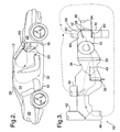
- Figure 2 is a side view of a vehicle having a HVAC system according to the subject invention;
- Figure 3 is a side of the HVAC module of Figure 1;
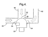
- Figure 4 is side view of a blower having three inlet ducts according to the subject invention;
- Figure 5 is a side view of an alternate embodiment of the HVAC module of Figure 1 ;
- Figure 6 is a side view of another embodiment of the HVAC module of Figure 1;
- Figure 7A is a graphical representation of an average outlet temperature of the HVAC module versus time for the subject invention;
- Figure 7B is a tabular representation of the average outlet temperature of the HVAC module versus time and a temperature improvement for the subject invention;
- Figure 8A is a graphical representation of a floor outlet temperature of the HVAC module versus time for the subject invention;
- Figure 8B is a tabular representation of the floor outlet temperature of the HVAC module versus time and a temperature improvement for the subject invention.
- Referring to the Figures, wherein like numerals indicate like or corresponding parts throughout the several views, a heating, ventilation, and air conditioning (HVAC) system is generally shown at 10 in Figure 1. The
HVAC system 10 is operable in a fresh air mode and a recirculation mode. TheHVAC system 10 draws air from outside avehicle 12 and vents the air into thevehicle 12 in the fresh air mode. TheHVAC system 10 also draws air from within thevehicle 12 and recirculates the air back into thevehicle 12 in the recirculation mode. It is to be appreciated that HVAC systems may be able to simultaneously mix the fresh, ambient air and the recirculated air. - Referring to Figure 2, the
vehicle 12 includes apassenger compartment 14 having afront 16 and aback 18. Adashboard 20 is located in thefront 16 of thepassenger compartment 14. Thevehicle 12 has anengine compartment 22 located at thefront 16 of thevehicle 12. The terms "front" and "back" are intended to be very general, and the structures that define and delimit thefront 16 andback 18 will, in any particular case, differ. Typically, thefront 16 would be defined by those structures infront 16 of a front seat passenger or driver, such as a windshield, thedashboard 20, and the like. Theback 18 would be defined by structures such as a shelf behind the back passengers and whatever structure separates the back seating from atrunk space 26. Thepassenger compartment 14 is bounded above by aroof structure 28 and below by afloor 30. Terms such as "front" and "back" are intended here to be inclusive, rather than exclusive, and relate more to the air movement inside thepassenger compartment 14, than to its structural features. That is, air will move generally fromfront 16 toback 18, in the fresh air mode, and will circulate back again generally fromback 18 tofront 16 in the recirculation mode. - The
HVAC system 10 includes ablower 32, shown in Figure 1, mounted in either the back of theengine compartment 22 or adjacent thedashboard 20, as is known in the art of HVAC systems. Theblower 32 is in fluid communication with thepassenger compartment 14 for circulating air from outside thevehicle 12 into and through thepassenger compartment 14 in the fresh air mode and for recirculating air from within thepassenger compartment 14 in the recirculation mode. Theblower 32 will be described in more detail below. - Referring to Figures 1 and 3, the
HVAC system 10 further includes a heating, ventilation, and air conditioning (HVAC)module 34 in fluid communication with and downstream of theblower 32 for warming and cooling the air to be circulated through thepassenger compartment 14 in both the fresh air mode and the recirculation mode. TheHVAC module 34 includes anevaporator 36, aheater core 38, and atemperature door 40, as is known in the art. Thetemperature door 40 is moveable to select the amount of air that flows through theheater core 38, as understood by those skilled in the art. The HVAC module shown in Figure 1 is a dual zone HVAC module that allow the driver and the passenger to select different temperatures. The subject invention is equally applicable with a single zone HVAC module or a dual mode HVAC module as known by those skilled in the art. - The
HVAC module 34 has outlets for venting the air into thevehicle 12. One outlet is adefrost duct 42 located in fluid communication with and downstream of theHVAC module 34 and adapted to be located above thedashboard 20 for venting the air into thepassenger compartment 14. Thedefrost ducts 42 vent air from theHVAC system 10 into thepassenger compartment 14. Thedefrost ducts 42 are typically located just below the windshield on thedashboard 20 to prevent fogging of the windshield. A second outlet is apanel outlet 44 venting air out thefront 16 of thedashboard 20, and a third outlet is afloor outlet 46 venting air out below thedashboard 20. - The
HVAC module 34 includes afirst inlet duct 48 in fluid communication with and upstream of theblower 32 for drawing ambient air from outside of thepassenger compartment 14 and through theblower 32 and theHVAC module 34 in the fresh air mode. TheHVAC module 34 further includes asecond inlet duct 50 in fluid communication with and upstream of theblower 32 and adapted to be located below thedashboard 20 for drawing air from below thedashboard 20 in thepassenger compartment 14 and through theblower 32 and theHVAC module 34 in the recirculation mode. Inlet ducts channel the flow of the air from either outside or inside the vehicle to the blower, as is known to those skilled in the art. The inlet ducts may be rectangular or circular depending upon the amount of space where the module is located in either the engine compartment or the passenger compartment. - The
blower 32 includes afirst blower port 52 interconnecting thefirst inlet duct 48 and theblower 32 and asecond blower port 54 interconnecting thesecond inlet duct 50 and theblower 32. The blower ports are typically apertures in the blower for connecting the inlet ducts to the blower. It should be understood that any connection of the inlet ducts to the blower would accomplish the subject invention. Ablower door 56 is connected to theblower 32 and is moveable between an open position and a closed position for selectively opening and closing theblower 32 ports. In one embodiment, shown in Figure 4, theblower door 56 is single door. It is preferable that theblower door 56 is further defined as afirst blower door 58 for opening and closing thefirst blower port 52 and asecond blower door 60 for opening and closing thesecond blower port 54, as best shown in Figure 3. - A
third inlet duct 62 is provided in fluid communication with and upstream of theblower 32 and located above thedashboard 20 for drawing air from thepassenger compartment 14 above thedashboard 20 and through theblower 32 and theHVAC module 34 in the recirculation mode. The third inlet duct is preferably of the same construction as that of the first and second inlet ducts. Theblower 32 has athird blower port 64 interconnecting thethird inlet duct 62 and theblower 32. Athird blower door 66 is utilized for opening and closing thethird blower port 64, when multiple blower doors are used in place of the single blower door described above. - The subject invention further includes a
dashboard port 68 located on thedashboard 20. The dashboard port is an aperture in the dashboard such that thethird inlet duct 62 and thedefrost duct 42 share thedashboard port 68 for drawing the air from thepassenger compartment 14 and venting the air back 18 into thepassenger compartment 14. It is to be appreciated thatmultiple dashboard ports 68 may be positioned within thepassenger compartment 14, such as a first dashboard port adapted to be located on thedashboard 20 of a driver side of thevehicle 12 and a second dashboard port adapted to be located on thedashboard 20 of a passenger side of thevehicle 12. - Referring to Figure 5, the
system 10 is characterised by theinlet duct 62 and thedefrost duct 42 converginginto asingle duct 70. Thesingle duct 70 is in fluid communication with thedashboard port 68. Adoor 72 is positioned within thesingle duct 70 and is moveable between an inlet mode for communicating thesingle duct 70 with the inlet duct and theblower 32 and an outlet mode for communicating thesingle duct 70 with thedefrost duct 42 and theHVAC module 34. When the door is in the inlet mode, thesingle duct 70 delivers air through theblower 32 and to theHVAC module 34. The air is then discharged from theHVAC module 34 through another outlet other than the single vent. - Referring to Figure 6, in another embodiment, the
single duct 70 may be used for both the recirculation and venting the air back into thepassenger compartment 14. Abaffle 74 extends along thesingle duct 70 and divides thesingle duct 70. Thesingle duct 70 is divided into afirst chamber 76 for drawing air in through thedashboard port 68 to the inlet duct and theblower 32 and asecond chamber 78 for venting air from theHVAC module 34 out through thedefrost duct 42 and thedashboard port 68. - Referring back to Figures 2 and 3, when the
HVAC system 10 is operated in fresh air mode, air enters thevehicle 12 through thefirst inlet duct 48 and vented through the outlets. The air exits thevehicle 12 from the rear thereby providing continuous fresh air throughout thepassenger compartment 14. In recirculation mode, air is drawn from within thevehicle 12 through either thesecond inlet duct 50 below thedashboard 20 or through thethird inlet duct 62 above thedashboard 20, or a mix of air from both the second inlet and thethird inlet ducts vehicle 12 through theoutlets floor outlets 46 and drawn through thesecond outlet duct 50, the airflow is short-circuited. The short circuit only warms the air below thedashboard 20 and does not warm the remainingpassenger compartment 14. However, when the air is being vented into thepassenger compartment 14 through thefloor outlets 46 and drawn into theinlet duct 62 located above thedashboard 20, the airflow is not short-circuited. - The air is forced to flow up and around the
dashboard 20 and throughout thepassenger compartment 14. By forcing the air to flow throughout thepassenger compartment 14, the air has an improved warm up rate, which improves the level of the occupant's comfort. - For example and with reference to Figure 7A, a graph of time versus temperature of air coming out of the
floor outlets 46 is illustrated. A first line, a baseline, is shown for anordinary system 10 having only a first inlet for ambient air and a second inlet below thedashboard 20 for recirculation. A second line is shown for thesystem 10 of the subject invention drawing air through the third inlet. At the 10-minute mark, theordinary system 10 has an average air temperature just after thefloor outlet 46 of 102.55 degrees Fahrenheit. The subject invention at the 10-minute mark has an average air temperature of 124.8 degrees Fahrenheit. The subject invention has increased the temperature by 21.7%. Theordinary system 10 takes 9.6 minutes to reach 100 degrees Fahrenheit, while thesubject invention system 10 takes only 7.0 minutes. This improves the warm-up rate of the air by 27%. Additional results are shown graphically in Figure 7A and in a tabular format in Figure 7B. - Referring to Figure 8A, a graph of time versus temperature of air about 8-16 inches away from the
floor outlets 46 after the air has mixed with the air in the passenger compartment is illustrated. A first line, the baseline, is shown for anordinary system 10 having only a first inlet for ambient air and a second inlet below thedashboard 20 for recirculation. A second line is shown for thesystem 10 of the subject invention drawing air through the third inlet. At the 10-minute mark, theordinary system 10 has an average air temperature within the passenger compartment about 8-16 inches from thefloor outlets 46 of 52.45 degrees Fahrenheit. The subject invention at the 10-minute mark has an average air temperature of 59.4 degrees Fahrenheit. The subject invention has increased the temperature by 13.25%. Theordinary system 10 takes 20 minutes to reach 75 degrees Fahrenheit, while thesubject invention system 10 takes only 14 minutes. This improves the warm-up rate of the air by 30%. Additional results are shown graphically in Figure 8A and in a tabular format in Figure 8B. - Obviously, many modifications and variations of the present invention are possible in light of the above teachings. The invention may be practiced otherwise than as specifically described in the description, as long as it falls within the scope of the appended claims, wherein that which is prior art is recited in the preamble of claim 1.
- In addition, the reference numerals in the claims are merely for convenience and are not to be read in any way as limiting.
Claims (8)
- A vehicle (12) having a heating, ventilation, and air conditioning (HVAC) system (10) being operable in a fresh air mode and a recirculation mode, said vehicle (12) comprising:a passenger compartment (14) having a front (16) and a back (18) ;a dashboard (20) located in said front (16) of said passenger compartment (14);a blower (32) in fluid communication with said passenger compartment (14) for circulating air from outside said vehicle (12) into and through said passenger compartment (14) in the fresh air mode and for recirculating air from within said passenger compartment (14) in the recirculation mode;a heating, ventilation, and air conditioning (HVAC) module (34) in fluid communication with and downstream of said blower (32) for warming and cooling the air to be circulated through said passenger compartment (14) in both the fresh air mode and the recirculation mode;an inlet duct (62) in fluid communication with and upstream of said blower (32) and located above said dashboard (20) for drawing air from said passenger compartment (14) above said dashboard (20) and through said blower (32) and said HVAC module (34) in the recirculation mode;a defrost duct (42) located in fluid communication with and downstream of said HVAC module (34) and located above said dashboard (20) for venting the air into said passenger compartment (14);wherein a dashboard port (68) is located on said dashboard (20) such that said inlet duct (62) and said defrost duct (42) share said dashboard port (68) for drawing the air from said passenger compartment (14) and venting air back (18) into said compartment (14), said defrost duct (42) converges into a single duct (70) in fluid communication with said dashboard port (68), said system characterised in that said single duct (70) comprising a baffle (74) extending along said single duct (70) and dividing said single duct (70) into a first chamber (76) for drawing air in through said dashboard port (68) to said inlet duct (62) and said blower (32) and a second chamber (78) for venting air from said HVAC module (34) out through said defrost duct (42) and said dashboard port (68).
- A vehicle as set forth in claim 1 further comprising a door (72) within said single duct (70) moveable between an inlet mode for communicating said single duct (70) with said inlet duct (62) and said blower (32) and an outlet mode for communicating said single duct (70) with said defrost duct (42) and said HVAC module (34).
- A vehicle as set forth in claim 1 further comprising further comprising a third inlet duct (62) in fluid communication with and upstream of said blower (32) and adapted to be located above the dashboard (20) for drawing air from above the dashboard (20) in the passenger compartment (14) and through said blower (32) and said HVAC module (34) in the recirculation mode.
- A vehicle as set forth in claim 3 wherein said blower (32) further comprises a first blower port (52) interconnecting said first inlet duct (48) and said blower (32), a second blower port (54) interconnecting said second inlet duct (50) and said blower (32), and a third blower port (64) interconnecting said third inlet duct (62) and said blower (32).
- A vehicle as set forth in claim 4 further comprising a blower door (56) moveable between an open position and a closed position for selectively opening and closing said first, second, and third blower ports (52, 54, 64).
- A vehicle as set forth in claim 5 wherein said blower door (56) is single door.
- A vehicle as set forth in claim 5 wherein said blower door (56) is further defined as a first blower door (58) for opening and closing said first blower port (52), a second blower door (60) for opening and closing said second blower port (54), a third blower door (66) for opening and closing said third blower port (64).
- A vehicle as set forth in claim 1 further comprising a first dashboard port adapted to be located on the dashboard (20) of a driver side of the vehicle (12) and a second dashboard port adapted to be located on the dashboard (20) of a passenger side of the vehicle (12).
Applications Claiming Priority (2)
| Application Number | Priority Date | Filing Date | Title |
|---|---|---|---|
| US10/222,099 US6669550B1 (en) | 2002-08-16 | 2002-08-16 | Heating, ventilation, and air conditioning system having improved air warm-up |
| US222099 | 2002-08-16 |
Publications (3)
| Publication Number | Publication Date |
|---|---|
| EP1389542A2 EP1389542A2 (en) | 2004-02-18 |
| EP1389542A3 EP1389542A3 (en) | 2004-06-30 |
| EP1389542B1 true EP1389542B1 (en) | 2006-06-28 |
Family
ID=29735472
Family Applications (1)
| Application Number | Title | Priority Date | Filing Date |
|---|---|---|---|
| EP03077393A Expired - Lifetime EP1389542B1 (en) | 2002-08-16 | 2003-07-30 | Heating, ventilation, and air conditioning system having improved air warm-up |
Country Status (3)
| Country | Link |
|---|---|
| US (1) | US6669550B1 (en) |
| EP (1) | EP1389542B1 (en) |
| DE (1) | DE60306465T2 (en) |
Cited By (1)
| Publication number | Priority date | Publication date | Assignee | Title |
|---|---|---|---|---|
| EP4722008A1 (en) * | 2024-10-02 | 2026-04-08 | Tesla, Inc. | Airflow optimization for cabin comfort |
Families Citing this family (8)
| Publication number | Priority date | Publication date | Assignee | Title |
|---|---|---|---|---|
| JP2005067402A (en) * | 2003-08-25 | 2005-03-17 | Denso Corp | Air conditioner for vehicles |
| FR2975344B1 (en) * | 2011-05-20 | 2016-04-29 | Valeo Systemes Thermiques | APPARATUS FOR HEATING, VENTILATION AND / OR AIR CONDITIONING COMPRISING AN AIR CIRCULATION CHANNEL CONVERTING A HEAT EXCHANGER |
| US9881460B2 (en) | 2012-03-28 | 2018-01-30 | Igt | Gaming system and method providing a bonus opportunity when a designated relationship exists between a plurality of randomly determined elements |
| US20140213168A1 (en) * | 2013-01-30 | 2014-07-31 | Visteon Global Technologies, Inc. | Hvac heat exchangers |
| JP6318854B2 (en) * | 2013-07-18 | 2018-05-09 | 株式会社デンソー | Air conditioner for vehicles |
| US20160229257A1 (en) * | 2015-02-10 | 2016-08-11 | Ford Global Technologies, Llc | Vehicle and vehicle cabin air extraction system |
| US10377347B2 (en) * | 2015-03-09 | 2019-08-13 | Ford Global Technologies, Llc | Low-profile ventilation system for a motor vehicle and related method of providing a low-profile ventilation system |
| JP6592466B2 (en) * | 2016-01-18 | 2019-10-16 | ハンオン システムズ | Air conditioning system for vehicles |
Family Cites Families (15)
| Publication number | Priority date | Publication date | Assignee | Title |
|---|---|---|---|---|
| DE3714771A1 (en) * | 1987-05-04 | 1988-12-01 | Bayerische Motoren Werke Ag | Arrangement of air-conditioning ducts in motor vehicles |
| DE4243165A1 (en) * | 1992-12-19 | 1994-06-23 | Behr Gmbh & Co | Automotive air-conditioning unit |
| FR2710294B1 (en) * | 1993-09-23 | 1995-11-24 | Valeo Thermique Habitacle | Installation of heating-ventilation-air conditioning of the passenger compartment of a motor vehicle. |
| US5391112A (en) | 1994-04-04 | 1995-02-21 | General Motors Corporation | Vehicle air inlet and filter assembly |
| GB9423776D0 (en) * | 1994-11-25 | 1995-01-11 | Acg Deutschland Gmbh | Dashboard assembly |
| US5879230A (en) | 1998-05-01 | 1999-03-09 | General Motors Corporation | Low profile air inlet assembly for vehicle air conditioning system |
| DE19843364C1 (en) * | 1998-09-22 | 2000-01-05 | Daimler Chrysler Ag | Ventilator grille used in passenger compartment of vehicle |
| US6077158A (en) | 1998-11-12 | 2000-06-20 | Daimlerchrysler Corporation | Air handling controller for HVAC system for electric vehicles |
| EP1222083A4 (en) | 1999-09-13 | 2004-05-06 | Fuel Man Inc | Vehicle air induction system |
| US6304803B1 (en) | 1999-09-22 | 2001-10-16 | Honda Giken Kogyo Kabushiki Kaisha | HVAC control system for an automobile |
| US6381973B1 (en) | 1999-10-04 | 2002-05-07 | Delphi Technologies, Inc. | Vehicle air cycle air conditioning system |
| US6382305B1 (en) | 1999-10-15 | 2002-05-07 | Calsonic Kansei Corporation | Heating ventilation, and air conditioning unit for automotive vehicles |
| JP3614058B2 (en) * | 1999-11-24 | 2005-01-26 | トヨタ自動車株式会社 | Air conditioner for vehicles |
| FR2824298B1 (en) * | 2001-05-04 | 2003-12-12 | Valeo Climatisation | AIR RECYCLING DEVICE FOR A VEHICLE INTERIOR |
| US6361429B1 (en) | 2001-05-07 | 2002-03-26 | Delphi Technologies, Inc. | Reduced noise automotive ventilation system |
-
2002
- 2002-08-16 US US10/222,099 patent/US6669550B1/en not_active Expired - Fee Related
-
2003
- 2003-07-30 DE DE60306465T patent/DE60306465T2/en not_active Expired - Fee Related
- 2003-07-30 EP EP03077393A patent/EP1389542B1/en not_active Expired - Lifetime
Cited By (1)
| Publication number | Priority date | Publication date | Assignee | Title |
|---|---|---|---|---|
| EP4722008A1 (en) * | 2024-10-02 | 2026-04-08 | Tesla, Inc. | Airflow optimization for cabin comfort |
Also Published As
| Publication number | Publication date |
|---|---|
| DE60306465T2 (en) | 2007-06-14 |
| US6669550B1 (en) | 2003-12-30 |
| DE60306465D1 (en) | 2006-08-10 |
| EP1389542A3 (en) | 2004-06-30 |
| EP1389542A2 (en) | 2004-02-18 |
Similar Documents
| Publication | Publication Date | Title |
|---|---|---|
| US6530831B1 (en) | Ventilating, heating and air-conditioning device for motor vehicle passenger compartment | |
| KR101445649B1 (en) | Air-conditioner for vehicle | |
| JPS633523Y2 (en) | ||
| US6595276B2 (en) | Vehicular heating and air conditioning unit including plural air-mixing spaces | |
| US8460073B2 (en) | Air conditioner for vehicle | |
| US6415851B1 (en) | Multi-zone temperature control system for HVAC air-handling assembly | |
| US20050124284A1 (en) | Airflow control in heating and air conditioning units | |
| KR101146430B1 (en) | Rear air conditioner for vehicle | |
| US6669550B1 (en) | Heating, ventilation, and air conditioning system having improved air warm-up | |
| JP3614058B2 (en) | Air conditioner for vehicles | |
| KR20110021074A (en) | Car air conditioner | |
| US20200023708A1 (en) | A conditioned air distribution system for a vehicle | |
| JP2021017066A (en) | Vehicular air conditioner | |
| US10220667B2 (en) | Dedicated floor bleed for an air conditioning system | |
| EP4420903A1 (en) | Vehicular air-conditioning device | |
| JP3686154B2 (en) | Air conditioner for automobile | |
| KR20200047931A (en) | Apparatus for air-ventilation of vehicle and method for controlling the same | |
| JP2004114889A (en) | Automotive air conditioners | |
| US20250010687A1 (en) | Vehicle air-conditioning device | |
| US20240174044A1 (en) | Air conditioner for vehicle | |
| US11059350B2 (en) | Vehicle having an air conditioning unit which has a preconditioning mode | |
| HU184644B (en) | Bus provided with heating and ventillating device | |
| KR0124859Y1 (en) | Heater Unit of Automotive Air Conditioning System | |
| JPH0136649Y2 (en) | ||
| KR20010109987A (en) | Air conditioner for a car |
Legal Events
| Date | Code | Title | Description |
|---|---|---|---|
| PUAI | Public reference made under article 153(3) epc to a published international application that has entered the european phase |
Free format text: ORIGINAL CODE: 0009012 |
|
| AK | Designated contracting states |
Kind code of ref document: A2 Designated state(s): AT BE BG CH CY CZ DE DK EE ES FI FR GB GR HU IE IT LI LU MC NL PT RO SE SI SK TR |
|
| AX | Request for extension of the european patent |
Extension state: AL LT LV MK |
|
| PUAL | Search report despatched |
Free format text: ORIGINAL CODE: 0009013 |
|
| AK | Designated contracting states |
Kind code of ref document: A3 Designated state(s): AT BE BG CH CY CZ DE DK EE ES FI FR GB GR HU IE IT LI LU MC NL PT RO SE SI SK TR |
|
| AX | Request for extension of the european patent |
Extension state: AL LT LV MK |
|
| RIC1 | Information provided on ipc code assigned before grant |
Ipc: 7B 60H 1/24 A |
|
| 17P | Request for examination filed |
Effective date: 20041230 |
|
| AKX | Designation fees paid |
Designated state(s): DE FR GB |
|
| 17Q | First examination report despatched |
Effective date: 20050607 |
|
| GRAP | Despatch of communication of intention to grant a patent |
Free format text: ORIGINAL CODE: EPIDOSNIGR1 |
|
| GRAS | Grant fee paid |
Free format text: ORIGINAL CODE: EPIDOSNIGR3 |
|
| GRAA | (expected) grant |
Free format text: ORIGINAL CODE: 0009210 |
|
| AK | Designated contracting states |
Kind code of ref document: B1 Designated state(s): DE FR GB |
|
| REG | Reference to a national code |
Ref country code: GB Ref legal event code: FG4D |
|
| REF | Corresponds to: |
Ref document number: 60306465 Country of ref document: DE Date of ref document: 20060810 Kind code of ref document: P |
|
| ET | Fr: translation filed | ||
| PLBE | No opposition filed within time limit |
Free format text: ORIGINAL CODE: 0009261 |
|
| STAA | Information on the status of an ep patent application or granted ep patent |
Free format text: STATUS: NO OPPOSITION FILED WITHIN TIME LIMIT |
|
| 26N | No opposition filed |
Effective date: 20070329 |
|
| GBPC | Gb: european patent ceased through non-payment of renewal fee |
Effective date: 20070730 |
|
| PG25 | Lapsed in a contracting state [announced via postgrant information from national office to epo] |
Ref country code: GB Free format text: LAPSE BECAUSE OF NON-PAYMENT OF DUE FEES Effective date: 20070730 |
|
| PGFP | Annual fee paid to national office [announced via postgrant information from national office to epo] |
Ref country code: FR Payment date: 20090710 Year of fee payment: 7 |
|
| PGFP | Annual fee paid to national office [announced via postgrant information from national office to epo] |
Ref country code: DE Payment date: 20090723 Year of fee payment: 7 |
|
| REG | Reference to a national code |
Ref country code: FR Ref legal event code: ST Effective date: 20110331 |
|
| PG25 | Lapsed in a contracting state [announced via postgrant information from national office to epo] |
Ref country code: DE Free format text: LAPSE BECAUSE OF NON-PAYMENT OF DUE FEES Effective date: 20110201 |
|
| REG | Reference to a national code |
Ref country code: DE Ref legal event code: R119 Ref document number: 60306465 Country of ref document: DE Effective date: 20110201 |
|
| PG25 | Lapsed in a contracting state [announced via postgrant information from national office to epo] |
Ref country code: FR Free format text: LAPSE BECAUSE OF NON-PAYMENT OF DUE FEES Effective date: 20100802 |