EP1388934A2 - Feedforward amplifier - Google Patents
Feedforward amplifier Download PDFInfo
- Publication number
- EP1388934A2 EP1388934A2 EP03254242A EP03254242A EP1388934A2 EP 1388934 A2 EP1388934 A2 EP 1388934A2 EP 03254242 A EP03254242 A EP 03254242A EP 03254242 A EP03254242 A EP 03254242A EP 1388934 A2 EP1388934 A2 EP 1388934A2
- Authority
- EP
- European Patent Office
- Prior art keywords
- distortion
- signal
- amplifier
- input signal
- amplified
- Prior art date
- Legal status (The legal status is an assumption and is not a legal conclusion. Google has not performed a legal analysis and makes no representation as to the accuracy of the status listed.)
- Withdrawn
Links
Images


Classifications
-
- H—ELECTRICITY
- H03—ELECTRONIC CIRCUITRY
- H03F—AMPLIFIERS
- H03F1/00—Details of amplifiers with only discharge tubes, only semiconductor devices or only unspecified devices as amplifying elements
- H03F1/32—Modifications of amplifiers to reduce non-linear distortion
- H03F1/3241—Modifications of amplifiers to reduce non-linear distortion using predistortion circuits
- H03F1/3247—Modifications of amplifiers to reduce non-linear distortion using predistortion circuits using feedback acting on predistortion circuits
-
- H—ELECTRICITY
- H03—ELECTRONIC CIRCUITRY
- H03F—AMPLIFIERS
- H03F1/00—Details of amplifiers with only discharge tubes, only semiconductor devices or only unspecified devices as amplifying elements
- H03F1/32—Modifications of amplifiers to reduce non-linear distortion
- H03F1/3223—Modifications of amplifiers to reduce non-linear distortion using feed-forward
- H03F1/3229—Modifications of amplifiers to reduce non-linear distortion using feed-forward using a loop for error extraction and another loop for error subtraction
- H03F1/3235—Modifications of amplifiers to reduce non-linear distortion using feed-forward using a loop for error extraction and another loop for error subtraction using a pilot signal
-
- H—ELECTRICITY
- H03—ELECTRONIC CIRCUITRY
- H03F—AMPLIFIERS
- H03F1/00—Details of amplifiers with only discharge tubes, only semiconductor devices or only unspecified devices as amplifying elements
- H03F1/42—Modifications of amplifiers to extend the bandwidth
- H03F1/48—Modifications of amplifiers to extend the bandwidth of aperiodic amplifiers
- H03F1/486—Modifications of amplifiers to extend the bandwidth of aperiodic amplifiers with IC amplifier blocks
Definitions
- This invention relates to a feedforward amplifier that, in a distortion detection loop, uses a main amplifier to amplify a plurality of signal groups wherein each has a different frequency band, and in a distortion compensation loop, also compensates for the distortion that arises in said main amplifier and particularly to a feedforward amplifier that is able to perform precise distortion compensation on a plurality of wideband signal groups as a whole without adopting broadband frequency-band characteristics for the auxiliary amplifier used to amplify the distortion detected by the distortion detection loop.
- a multi-carrier signal that contains a plurality of carriers at stipulated frequency intervals that are each modulated appropriately is transmitted wirelessly after high-frequency amplification.
- various kinds of distortion including intermodulation distortion and the like may occur. This distortion becomes an impediment to achieving normal and high-quality communication.
- the amplifiers used for the amplification of multi-carrier signals are required to have good linearity over the entire frequency band to which the multi-carrier signal belongs.
- One example of a method of achieving an ultra-low-distortion amplifier suited to the amplification of a multi-carrier signal is the feedforward (FF) amplification scheme.
- the signal path from the signal input terminal via the main amplifier to the signal output terminal, namely the signal path for conveying the signal to be amplified and the amplified signal is referred to as the "main line.”
- a distortion detection path that couples a signal branching from a point after the main amplifier in the main line to a signal branching from a point before the main amplifier in the main line.
- the loop consisting of the main line and the distortion detection path is called the distortion detection loop.
- the electrical lengths of the signal paths over which both the signal conveyed along the main line and the signal conveyed along the distortion detection path are equal to each other, and, if both signals have mutually opposite phases at the same amplitude, then with the aforementioned signal coupling action, it is possible to cancel the carrier-wave components and extract a signal equivalent to the distortion arising in the main amplifier and its peripheral circuits.
- a distortion compensation path is provided to recouple the signal extracted by the distortion detection loop, namely a signal equivalent to the distortion, to the signal on the main line.
- the loop consisting of the main line and the distortion compensation loop is called the distortion compensation loop.
- signal delay in the distortion compensation loop is compensated for in the main line and as long as adjustment of the amplitude and phase is performed appropriately in the distortion compensation loop so that the distortion components contained in the signal on the main line have the same amplitude and the opposite phase from the distortion signal obtained from the distortion compensation loop, it is possible to compensate for the distortion occurring in the main amplifier.
- FIG. 3 shows an example of the constitution of a conventional FF amplifier.
- FF amplifier In the FF amplifier shown in the figure, three directional couplers (hybrid) 41, 46 and 51 are utilized to form a distortion detection loop L11 consisting of the main line and the distortion detection path and a distortion compensation loop L12 consisting of the main line and the distortion compensation path.
- the signal path from the signal input terminal P2 via the first directional coupler 41, first variable attenuator 42, first variable phase shifter 43, first coupler 61, main amplifier (first amplifier) 44, second directional coupler 46, second coaxial delay line 47, third directional coupler 51 and third coupler 63 to the signal output terminal Q2 is equivalent to the main line.
- the signal path from the signal input terminal P2 via the first directional coupler 41 and first coaxial delay line 45 to the output terminal of the second directional coupler 46 is equivalent to the distortion detection path.
- the signal path from the output terminal of the second directional coupler 46 via the second coupler 62, second variable attenuator 48, second variable phase shifter 49 and auxiliary amplifier (second amplifier) 50 to the output terminal of the third directional coupler 51 is equivalent to the distortion compensation path.
- terminating resistors R11 and R12 are connected to one input terminal of the first directional coupler 41 and one output terminal of the third directional coupler 51 as terminating dummy loads. These terminating resistors R11 and R12 have an impedance of Z 0 equal to the characteristic impedance of the path.
- the three couplers 61, 62 and 63 and a control circuit 71 which has a control signal generation circuit 72 constitute the feedback control system which performs control using pilot signals and the like.
- this signal is input via the first directional coupler 41 to the first variable attenuator 42 and first variable phase shifter 43, where its amplitude and phase are adjusted, and then further input to the main amplifier 44 where it is amplified.
- the signal amplified by the main amplifier 44 is input via the second directional coupler 46 and second coaxial delay line 47 to the third directional coupler 51, and further output from the third directional coupler 51 via the signal output terminal Q2 to the circuits after this FF amplifier.
- the second coaxial delay line 47 is a delay line that compensates for the signal delay arising in the circuit constituting the distortion compensation loop L12, e.g., the auxiliary amplifier 50.
- the signal input from the signal input terminal P2 is divided into two branches by the first directional coupler 41.
- the two branches of the signal are the same signal from the standpoint of the constitution of component frequencies, and the signal branch supplied to the main line side is amplified by the main amplifier 44, while the signal branch supplied to the distortion detection path side is supplied at roughly its original amplitude from the first directional coupler 41 via the first coaxial delay line 45 to the second directional coupler 46.
- the first coaxial delay line 45 is a delay line for compensating for the signal delay arising in the main amplifier 44 in particular.
- the signal supplied via the first coaxial delay line 45 to the second directional coupler 46 is coupled by this second directional coupler 46 to the amplified signal that contains distortion components.
- the second directional coupler 46 divides the signal containing distortion components output from the main amplifier 44 into two branches.
- the two branches of the signal are the same signal from the standpoint of the constitution of component frequencies; one signal branch is supplied to the main line side while the other signal branch is supplied to the distortion compensation path side
- the second directional coupler 46 couples this other signal branch to the signal input via the first coaxial delay line 45, thereby canceling the carrier-wave components within the other signal branch and extracting the distortion components from this other signal branch.
- the distortion signal obtained as a result of this coupling is supplied from the second directional coupler 46 to the second variable attenuator 48, second variable phase shifter 49 and auxiliary amplifier 50 which constitute the distortion compensation path, its amplitude and phase are adjusted in the second variable attenuator 48 and second variable phase shifter 49, and moreover it is amplified by the auxiliary amplifier 50 and provided as input to the third directional coupler 51.
- the distortion signal input to the third directional coupler 51 is coupled in the third directional coupler 51 to the signal input via the second coaxial delay line 47, the distortion contained within this signal is cancelled and this signal with the distortion cancelled is output from signal output terminal Q2.
- the first coaxial delay line 45 is a means of applying the delay time D 1 to the signal and synchronizing the timing among the carrier-wave components.
- the first variable attenuator 42, first variable phase shifter 43 and the control circuit 71 which exerts control so as to adjust the signal attenuation G 1 in the first variable attenuator 42 and the signal phase shift ⁇ 1 in the first variable phase shifter 43 to optimal values are the means of bringing the carrier wave components to the same amplitude and opposite phase.
- first coaxial delay line 45, first variable attenuator 42, first variable phase shifter 43 and control circuit 71 are means of adjusting the output from the second directional coupler 46 so that a signal containing only distortion components and containing no carrier-wave components is supplied to the auxiliary amplifier 50.
- the signal coming via the auxiliary amplifier 50 be a signal that contains only distortion components and contains no carrier-wave components.
- the generation of distortion in the auxiliary amplifier 50 is negligible when the distortion detection loop L11 is operating normally, so it is possible to set an appropriate value for the delay time D 1 of the first coaxial delay line 45 and also have the control circuit 71 appropriately control the first variable attenuator 42 and first variable phase shifter 43 to satisfy this first condition.
- the distortion components within the signal coming via the second coaxial delay line 47 and the distortion components within the signal coming via the auxiliary amplifier 50 are necessary at the time of coupling in the third directional coupler 51 at the same timing, same amplitude and opposite phase from each other.
- the second coaxial delay line 47 is a means of applying the delay time D 2 to the signal and synchronizing the timing among the carrier-wave components.
- the second variable attenuator 48, second variable phase shifter 49, and the control circuit 71 which exerts control so as to adjust the signal attenuation G 2 in the second variable attenuator 48 and the signal phase shift ⁇ 2 in the second variable phase shifter 49 to optimal values are the means of bringing the carrier wave components to the same amplitude and opposite phase.
- the process of exerting control so as to adjust the first signal attenuation G 1 and first signal phase shift ⁇ 1 and the second signal attenuation G 2 and signal phase shift ⁇ 2 to optimal values namely the process of optimizing the state of the distortion detection loop L11 and distortion compensation loop L12 is executed by the control circuit 71.
- this optimization process is executed by the control circuit 71 which operates under the control of a central processing unit (CPU).
- CPU central processing unit
- the second coupler 62 detects a portion of the output of the second directional coupler 46 to the distortion compensation path, and outputs the results of this detection to the control signal generation circuit 72 of the control circuit 71. Then, the control signal generation circuit 72 controls the first signal attenuation G 1 of the first variable attenuator 42 and the first signal phase shift ⁇ 1 of the first variable phase shifter 43 so that only the distortion generated by the second coupler 62 is detected.
- control signal generation circuit 72 of the control circuit 71 generates a stipulated pilot signal and outputs this pilot signal to the first coupler 61.
- the first coupler 61 combines this pilot signal with the output from the first variable phase shifter 43 and outputs this composite signal to the main amplifier 44.
- the third coupler 63 detects the components of the pilot signal inserted into the input signal subject to amplification with the first coupler 61 and outputs the results of this detection to the control signal generation circuit 72 of the control circuit 71.
- the control signal generation circuit 72 controls the signal attenuation G 2 of the second variable attenuator 48 and the signal phase shift ⁇ 2 of the second variable phase shifter 49, thereby achieving good compensation of distortion.
- the present invention came about in light of the aforementioned circumstances and has as its object to provide a feedforward amplifier that has a distortion detection loop and a distortion compensation loop, and that uses a main amplifier to amplify a plurality of signal groups wherein each has a different frequency band, and in a constitution wherein the distortion arising in this main amplifier is compensated for, it is able to perform precise distortion compensation on a plurality of wideband signal groups as a whole without adopting broadband frequency-band characteristics for the auxiliary amplifier used to amplify the distortion detected by the distortion detection loop.
- the present invention differs on the point that its constitution is such that distortion is amplified by a different auxiliary amplifier for each of the various input signal groups arising when input signal groups (e.g., multi-carrier signals) have a plurality of different frequency bands.
- a plurality of groups of signals having different frequency bands are input, a plurality of input signal groups are amplified with a main amplifier in a distortion detection loop and the distortion arising in this main amplifier is detected, and in a distortion compensation loop the distortion detected by the distortion detection loop is removed from the signal amplified by this main amplifier, and at this time, the distortion compensation loop is constituted as follows.
- the distortion compensation loop has the same number of distortion amplification systems as the number of input signal groups, and each distortion amplification system uses an auxiliary amplifier to amplify the distortion for each input signal group that is included in the distortion detected by the distortion detection loop. Moreover, the distortion compensation loop removes the sum total of the distortion from each input signal group amplified by this plurality (to wit, the same number as the number of input signal groups) of distortion amplification systems from the amplified signal from the main amplifier.
- the distortion compensation loop is provided with input signal groups corresponding to each input signal group and the same number of distortion amplification systems, and the distortion of each input signal group is amplified by the auxiliary amplifier of each distortion amplification system, so for example, even without adopting broadband frequency band characteristics for the auxiliary amplifiers used to amplify the distortion detected by the distortion detection loop, to wit, even without adopting broadband frequency band characteristics for the auxiliary amplifiers of each distortion amplification system, it is possible to perform precise distortion compensation for the plurality of input signal groups.
- the plurality of signal groups each has a different frequency band
- various frequency bands may be used as the frequency bands of each of the signal groups.
- mutually separated frequency bands may be used as the frequency bands of each signal group.
- Various numbers may be used as the number of the plurality of signal groups.
- each of the signal groups may have a frequency bandwidth, for example.
- a signal with one frequency for example, may also be used as a signal group according to the present invention, and the present invention also encompasses such an embodiment.
- compositions may be used as the composition of the distortion detection loop and the composition of the distortion removal loop.
- various amplifiers may be used as the main amplifier.
- Specific examples of the main amplifier include a common amplifier that is able to amplify signals of a plurality of frequencies all at once.
- the distortion detected by the distortion detection loop includes distortion for each of the respective signal groups, to wit, the distortion arising due to the amplification of the respective signal groups by the main amplifier.
- distortion for each input signal group may include, for example, tertiary distortion arising in the frequency band on the upside (high-frequency side) of each of these input signal groups (upside tertiary distortion), tertiary distortion arising in the frequency band on the downside (low-frequency side) of each of these input signal groups (downside tertiary distortion), etc.
- various degrees of precision may be used as the precision of removal of distortion from the amplified signal from the main amplifier in the distortion compensation loop as long as they are practically effective, to wit, various degrees of precision may be used as the precision of distortion compensation performed in the distortion compensation loop as long as they are practically effective.
- auxiliary amplifiers may be used as the auxiliary amplifiers. Specific examples include amplifiers that have characteristics that are good for the amplification of signals in the frequency bands of distortion subject to amplification by each when used as the auxiliary amplifiers for the distortion amplification systems, and even more specific examples include amplifiers wherein the amplitude characteristics and phase characteristics are flat during amplification over the frequency bands of distortion subject to amplification by each.
- the distortion amplification systems used may be ones of various constitutions.
- the sum total of the distortion for each input signal group amplified by all of the distortion amplification systems may be removed from the amplified signal from the main amplifier, or the distortion arising in the main amplifier for all of the input signal groups may be removed from this amplified signal.
- the distortion compensation loop comprises division means consisting of a divider, for example, that divides the distortion detected by the distortion detection loop among each of the distortion amplification systems, and combining means consisting of a combiner, for example, that obtains the sum total of distortion in each input signal group amplified by the auxiliary amplifier of each distortion amplification system.
- the distortion amplification systems that have distortion compensation loops are provided with filters that extract the distortion in the input signal groups corresponding to each, and the distortion extracted by these filters is amplified by auxiliary amplifiers.
- the distortion in each input signal group subject to amplification can be extracted by the filter to remove any unnecessary frequency components.
- filters may be used as the filters.
- filters having such characteristics that they extract signals in the frequency band of distortion subject to amplification by the respective distortion amplification systems and in the frequency band of the input signal group corresponding to this distortion may be used as the filters of the respective distortion amplification systems.
- the various distortion amplification systems having distortion compensation loops are constituted as follows.
- a bandpass filter extracts the distortion in the corresponding respective input signal group
- an amplitude changer changes the amplitude of the distortion extracted by the bandpass filter
- a phase changer changes the phase of the distortion extracted by the bandpass filter
- an auxiliary amplifier amplifies the distortion after its amplitude is changed by the amplitude changer and its phase is changed by the phase changer.
- the mode of changing the amplitude of the distortion for example, a mode of attenuating the distortion to decrease the amplitude of said distortion, or a mode of amplifying the distortion to increase the amplitude of said distortion may be used.
- variable attenuator that has the function of attenuating the signal with a variable attenuation
- a variable amplifier that has the function of amplifying the signal with a variable amplification, for example, may be used as the amplitude changer.
- variable phase shifter that has the function of changing the phase of the signal with a variable amount of phase shift, for example, may be used as the phase changer.
- the order of using the amplitude changer to change amplitude of the distortion and using the phase changer to change the phase of the distortion may be arbitrary. Specifically, a mode wherein the phase of the distortion is changed after changing the amplitude of the distortion may be used, or a mode wherein the amplitude of the distortion is changed after changing the phase of the distortion may be used. Note that at the time of changing the amplitude or phase of the distortion, there may be cases wherein only the amplitude of the distortion is changed, cases wherein only the phase of the distortion is changed, or cases wherein neither the amplitude nor the phase of the distortion is changed.
- bandpass filters that have flat delay and flat amplification in the frequency band of the extracted distortion is used as the bandpass filter provided in the distortion amplification systems that have distortion compensation loops.
- flat delay in the frequency band of the extracted distortion is defined to be a characteristic wherein the delay arising over the entire range of distortion is the same or on the same level when distortion is extracted in said frequency band.
- flat amplification in the frequency band of the extracted distortion is defined to be a characteristic wherein the amplification arising over the entire range of distortion is the same or on the same level when distortion is extracted in said frequency band.
- control is exerted using pilot signals as follows.
- pilot signals are provided for each of the input signal groups, and in this constitution, the number of pilot signals is the same as the number of input signal groups.
- pilot signal synthesizing means is provided for each input signal group for the plurality of input signal groups prior to amplification by the main amplifier provided in the distortion detection loop, and synthesizes the same number of pilot signals as the number of input signal groups.
- Pilot signal corresponding signal detection means detects signals corresponding to each pilot signal contained within the amplified signal from the main amplifier from which distortion is removed by the distortion compensation loop.
- Pilot signal control means controls each of the distortion amplification systems having distortion compensation loops based on the results of detection by the pilot signal corresponding signal detection means so that the distortion contained in the amplified signal from the main amplifier with distortion removed by the distortion compensation loop is reduced.
- the distortion amplification system corresponding to each of the respective input signal groups is controlled based on pilot signals corresponding to the each of the respective input signal groups, so the distortion contained in the amplified signal from the main amplifier with distortion removed is reduced, so it is possible to perform precise distortion compensation for each input signal group.
- the distortion contained in the amplified signal from the main amplifier from which distortion is removed is equivalent to the residual distortion not removed by this distortion removal.
- a mode of synthesizing the pilot signals for the plurality of input signal groups immediately prior to the main amplifier may be used, or another mode may also be used.
- signals having various frequencies may be used as the pilot signals for each input signal group; it is preferable to use signals having frequencies on the inside of the distortion frequency band of the input signal groups in question, or frequencies nearby on the outside, for example, and it is preferable to use signals having frequencies different from the frequencies constituting the distortion in the input signal groups, for example.
- pilot signals may be used as the pilot signals.
- pilot signal synthesizing means one that synthesizes pilot signals individually for each input signal group may be used, or one that synthesizes pilot signals for a plurality of input signal groups altogether may also be used.
- signals corresponding to the pilot signals detected by the pilot signal corresponding signal detection means signals having the same frequency as the frequency of the various pilot signals, for example, are detected.
- pilot signal corresponding signal detection means one that detects the signals corresponding to each pilot signal individually may be used, or one that detects signals corresponding to a plurality of pilot signals altogether may also be used.
- the mode of exerting control in order to reduce the distortion contained in the amplified signal from the main amplifier from which distortion is removed by the distortion compensation loop, it is possible to use a mode of control such that the level of the signal detected by the pilot signal corresponding signal detection means becomes small, for example, or it is more preferable to use a mode of control such that the level of this signal is minimized.
- the mode of controlling the various distortion amplification systems having distortion compensation loops it is possible to use a mode such that the change in amplification of the amplification changer or the phase change of the phase changer is controlled with respect to the amplification changer or phase changer provided in each distortion amplification system, for example.
- the feedforward amplifier according to the present invention as described above is suitable for use in base station units and relay station units provided in cellular phone systems or Personal Handy phone Systems (PHS) or other mobile communications systems.
- PHS Personal Handy phone Systems
- a feedforward amplifier such as that described above is provided, and multi-carrier or other signals for the mobile station units serving as the other party in communications are amplified by this feedforward amplifier and compensation for the distortion arising at the time of this amplification is performed, and then the amplified signal is transmitted wirelessly to the other party.
- various constitutions may be used for the constitution of the mobile communications system, base station unit, relay station unit, mobile station unit or the like.
- CDMA Code Division Multiple Access
- TDMA Time Division Multiple Access
- FDMA Frequency Division Multiple Access
- CDMA Code Division Multiple Access
- CDMA Code Division Multiple Access
- TDMA Time Division Multiple Access
- FDMA Frequency Division Multiple Access
- FIG. 1 shows an example of a feedforward amplifier (FF amplifier) according to the present invention.
- the FF amplifier in this example is used in the base station unit of a mobile communications system, and uses a main amplifier to amplify a multi-carrier signal subject to wireless transmission by this base station unit, and then compensates for the distortion generated at the time of this amplification.
- this example illustrates the case in which the multi-carrier signal input to the FF amplifier in this example consists of two signal groups (the first input signal group and the second input signal group) which have different frequency bandwidths and these frequency bandwidths are separated from each other.
- FF amplifier of this embodiment three directional couplers (hybrid) 1, 6 and 19 are provided between the signal input terminal P1 and the signal output terminal Q1.
- first variable attenuator 2 first variable phase shifter 3
- first coupler 21 fourth coupler 22
- main amplifier (first amplifier) 4 provided along one line
- first coaxial delay line 5 provided along the other line.
- Second directional coupler 6 and the third directional coupler 19 are a second coaxial delay line 7 provided along one line and a second coupler 23, fourth variable phase shifter 8, two distortion amplification systems (the first distortion amplification system and the second distortion amplification system), a fifth directional coupler 17 and a distortion amplifier (fourth amplifier) 18 provided along the other line.
- the first distortion amplification system is provided with a first bandpass filter (BPF) 9, second variable attenuator 10, second variable phase shifter 11 and an auxiliary amplifier (second amplifier) 12, while the second distortion amplification system is provided with a second bandpass filter 13, third variable attenuator 14, third variable phase shifter 15 and an auxiliary amplifier (second amplifier) 16.
- BPF bandpass filter
- second amplifier second amplifier
- a third coupler 24 and a fifth coupler 25 are provided between the third directional coupler 19 and the signal output terminal Q1.
- terminating resistors R1 through R4 are connected to one input terminal of the first directional coupler 1, one output terminal of the third directional coupler 19, one input terminal of the fourth variable phase shifter 8, and one output terminal of the fifth directional coupler 17 as terminating dummy loads. These terminating resistors R1 through R4 have an impedance of Z 0 equal to the characteristic impedance of the path.
- the couplers 21 through 25 and a control circuit 31 which has a control signal generation circuit 372 constitute the feedback control system which performs control using pilot signals and the like.
- the aforementioned one line between the first directional coupler 1 and the second directional coupler 6, and the aforementioned other lie between the second directional coupler 6 and the third directional coupler 19 constitute the main line;
- the aforementioned other line between the first directional coupler 1 and second directional coupler 6 constitutes the distortion detection path;
- the aforementioned other line between the second directional coupler 6 and the third directional coupler 19 constitute the distortion compensation path.
- the loop consisting of the aforementioned one line (main line) between the first directional coupler 1 and the second directional coupler 6 and the distortion detection path forms the distortion detection loop L1
- the loop consisting of the aforementioned one line (main line) between the second directional coupler 6 and the third directional coupler 19 and the distortion compensation path forms the distortion compensation loop L2.
- the constitution and operation of the FF amplifier according to the present embodiment are identical to the constitution and operation of the FF amplifier shown in FIG. 3 above with the exception of the fact that a plurality of distortion amplification systems are provided in the distortion compensation loop L2, and the couplers 21, 22, 24 and 25 are provided corresponding to the plurality of pilot signals.
- the operation of inputting a signal from the signal input terminal P1 and using the distortion detection loop L1 to detect the distortion arising in the main amplifier 4 is identical to that in the case of the FF amplifier shown in FIG. 3 above.
- the distortion component signal extracted by the second directional coupler 6 is sent to the fourth variable phase shifter 8.
- the fourth variable phase shifter 8 divides the input distortion component signal into two branches, so one signal branch is output to the first bandpass filter 9 of the first distortion amplification system, while the other signal branch is output to the second bandpass filter 13 of the second distortion amplification system.
- the one signal branch thus supplied is filtered by the first bandpass filter 9 to extract only the frequency band of the first input signal group contained in the aforementioned one branch signal and the frequency band of the distortion generated in the main amplifier 4 due to the first input signal group, and this extracted signal (called the first extracted signal) is output to the second variable attenuator 10.
- the first extracted signal thus extracted is attenuated by the second variable attenuator 10, has its phase changed by the second variable phase shifter 11, and is amplified by the auxiliary amplifier 12 and output to the fifth directional coupler 17.
- the first bandpass filter 9 only the first input signal group and the distortion generated in the main amplifier 4 due to the first input signal group is extracted by the first bandpass filter 9 and amplified and the like.
- the other signal branch thus supplied is filtered by the second bandpass filter 13 to extract only the frequency band of the second input signal group contained in the aforementioned other branch signal and the frequency band of the distortion generated in the main amplifier 4 due to the second input signal group, and this extracted signal (called the second extracted signal) is output to the third variable attenuator 14.
- the second extracted signal thus extracted is attenuated by the third variable attenuator 14, has its phase changed by the third variable phase shifter 15, and is amplified by the auxiliary amplifier 16 and is output to the fifth directional coupler 17.
- the second input signal group and the distortion generated in the main amplifier 4 due to the second input signal group is extracted by the second bandpass filter 13 and amplified and the like.
- the fifth directional coupler 17 couples the signal input from the auxiliary amplifier 12 of the first distortion amplification system to the signal input from the auxiliary amplifier 16 of the second distortion amplification system, and outputs the results of this coupling to the distortion amplifier 18.
- the distortion amplifier 18 amplifies the coupled signal thus input and outputs it to the third directional coupler 19.
- the third directional coupler 19 removes from the signal input via the second coaxial delay line 7 the distortion signal input via the distortion amplifier 18 through the second distortion amplification system, and outputs the signal with this distortion signal removed.
- the distortion of the first input signal group is extracted and amplified and the like by the first distortion amplification system and then removed from the signal on the main line side by the third directional coupler 19, and also, the distortion of the second input signal group is extracted and amplified and the like by the second distortion amplification system and then removed from the signal on the main line side by the third directional coupler 19.
- the second variable attenuator 10 receives control signals from the control signal generation circuit 32 of the control circuit 31 and thus varies the signal attenuation G 2 based on these control signals.
- the second variable phase shifter 11 receives control signals from the control signal generation circuit 32 of the control circuit 31 and thus varies the signal phase shift ⁇ 2 based on these control signals.
- the third variable attenuator 14 receives control signals from the control signal generation circuit 32 of the control circuit 31 and thus varies the signal attenuation G 3 based on these control signals.
- the third variable phase shifter 15 receives control signals from the control signal generation circuit 32 of the control circuit 31 and thus varies the signal phase shift ⁇ 3 based on these control signals.
- the control circuit 31 adjusts the second signal attenuation G 2 of the second variable attenuator 10 and the signal phase shift ⁇ 2 of the second variable phase shifter 11.
- the control circuit 31 adjusts the signal attenuation G 3 of the third variable attenuator 14 and the signal phase shift ⁇ 3 of the third variable phase shifter 15.
- first bandpass filter 9 provided in the first distortion amplification system and the second bandpass filter 13 provided in the second distortion amplification system preferably have a flat delay characteristic and flat amplitude characteristic, and thus it is possible to prevent disturbance in the phase or amplitude of the processed signals or deterioration in the precision of distortion compensation.
- the FF amplifier according to this embodiment it is possible to perform distortion compensation in the first input signal group extracted by the first bandpass filter 9 provided in the first distortion amplification system and its distortion frequency bandwidth, and also, it is possible to perform distortion compensation in the second input signal group extracted by the second bandpass filter 13 provided in the second distortion amplification system and its distortion frequency bandwidth. Accordingly, with the FF amplifier according to this embodiment, it is possible to perform distortion compensation over a wider band than that of the conventional FF amplifier shown in FIG. 3 above.
- the second coupler 23 detects a portion of the output from the second directional coupler 6 to the distortion compensation path, and outputs the results of this detection to the control signal generation circuit 32 of the control circuit 31. Moreover, the control signal generation circuit 32 controls the first signal attenuation G 1 of the first variable attenuator 2 and the first signal phase shift ⁇ 1 of the first variable phase shifter 3 so that only the distortion arising in the main amplifier 4 is detected by the second coupler 23.
- the distortion arising in the main amplifier 4 includes the distortion due to the first input signal group and the distortion due to the second input signal group.
- control signal generation circuit 32 of the control circuit 31 generates the stipulated first pilot signal corresponding to the first input signal group and outputs this first pilot signal to the first coupler 21.
- the first coupler 21 combines this pilot signal with the output from the first variable phase shifter 3 and outputs this composite signal to the second coupler 22.
- control signal generation circuit 32 of the control circuit 31 generates the stipulated second pilot signal corresponding to the second input signal group and outputs this second pilot signal to the fourth coupler 22.
- the fourth coupler 22 combines this pilot signal with the output from the first coupler 21 and outputs this composite signal to the main amplifier 4.
- the third coupler 24 detects the components of the first pilot signal inserted into the input signal subject to amplification by the first coupler 21, and outputs the results of this detection to the control signal generation circuit 32 of the control circuit 31. Based on the results of detection input from the third coupler 24, the control signal generation circuit 32 controls the second signal attenuation G 2 of the second variable attenuator 10 and the signal phase shift ⁇ 2 of the second variable phase shifter 11 provided in the first distortion amplification system corresponding to the first input signal group, and thereby achieves good distortion compensation with respect to the distortion of the first input signal group.
- the fifth coupler 25 detects the components of the second pilot signal inserted into the input signal subject to amplification by the fourth coupler 22, and outputs the results of this detection to the control signal generation circuit 32 of the control circuit 31. Based on the results of detection input from the fifth coupler 25, the control signal generation circuit 32 controls the signal attenuation G 3 of the third variable attenuator 14 and the signal phase shift ⁇ 3 of the third variable phase shifter 15 provided in the second distortion amplification system corresponding to the second input signal group, and thereby achieves good distortion compensation with respect to the distortion of the second input signal group.
- auxiliary amplifier 12 corresponding to the two input signal groups of the first input signal group and the second input signal group
- auxiliary amplifier 16 of the second distortion amplification system
- two pilot signals are used.
- a constitution wherein two pilot signals are inserted for the signals subject to amplification and a constitution wherein signals corresponding to the two pilot signals are detected from the amplified signals after distortion are adopted.
- the lower the level of the signal corresponding to the first pilot signal contained in the amplified signal after distortion compensation or the signal corresponding to the second pilot signal is, the smaller the distortion in the first input signal group or the distortion in the second input signal group contained in this amplified signal after distortion compensation becomes.
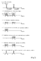
- FIG. 2 shows an example of the case in which a signal consisting of a signal group in the wideband W-CDMA protocol and a Personal Communications Services (PCS) signal group is input to the FF amplifier according to this embodiment and amplified. Note that the graphs in FIG. 2(a) through FIG. 2(g) have the frequency on the x-axis and the signal level on the y-axis.
- PCS Personal Communications Services
- the first input signal group is a PCS signal group and the second input signal group is a W-CDMA signal group.
- FIG. 2(b) shows, as one example of the signals output from the main amplifier 4, the first input signal group and second input signal group amplified by the main amplifier 4, the first pilot signal (PILOT1) amplified by the main amplifier 4 after insertion to the first input signal group, the second pilot signal (PILOT2) amplified by the main amplifier 4 after insertion to the second input signal group, the distortion arising in the main amplifier 4 due to the first input signal group and the distortion arising in the main amplifier 4 due to the second input signal group.
- PILOT1 the first pilot signal
- PILOT2 the second pilot signal
- the distortion in the first input signal group may include distortion in the upside frequency band having a frequency bandwidth ⁇ F 1 and distortion in the downside frequency band having a frequency bandwidth ⁇ F 1 , for example.
- the distortion in the second input signal group may include distortion in the upside frequency band having a frequency bandwidth ⁇ F 2 and distortion in the downside frequency band having a frequency bandwidth ⁇ F 2 , for example.
- the frequency bandwidth of the second input signal group is higher than the frequency bandwidth of the first input signal group, and the frequency gap ⁇ F 3 between the distortion in the upside frequency band due to the first input signal group and the distortion in the downside frequency band due to the second input signal group is appropriately wide.
- the first pilot signal and second pilot signal are shown by dotted lines.
- the distortion arising in the main amplifier 4 and the pilot signal are set to the same frequency, but it is preferable to set the pilot signals to a frequency at which distortion does not occur.
- FIG. 2(c) shows an example of the distortion components detected by the second coupler 23, where only the distortion components consisting of the distortion in the first input signal group and the distortion in the second input signal group are extracted.
- FIG. 2(d) shows an example of the distortion in the first input signal group amplified by the auxiliary amplifier 12 of the first distortion amplification system, where only the distortion of the first input signal group is amplified.
- FIG. 2(e) shows an example of the distortion in the second input signal group amplified by the auxiliary amplifier 16 of the second distortion amplification system, where only the distortion of the second input signal group is amplified.
- FIG. 2(f) shows an example of the distortion amplified by distortion amplifier 18, where the distortion of the first input signal group and the distortion of the second input signal group is amplified.
- FIG. 2(g) shows an example of the signal output from the signal output terminal Q1, showing the amplified first input signal group and second input signal group, where the distortion arising in the main amplifier 4 is compensated for by the distortion amplified by the distortion amplifier 18 in the third directional coupler 19.
- the FF amplifier has a feedforward loop consisting of a distortion detection loop and distortion compensation loop, and in the distortion compensation loop, the fourth directional coupler 8 which functions as a divider divides the distortion arising in the main amplifier 4, the bandpass filters 9 and 13, variable attenuators 10 and 14, second variable phase shifters 11 and 15 and auxiliary amplifiers 12 and 16 provided for each input signal group perform the amplification and other processes on each input signal group, and thereby the fifth directional coupler 17 which functions as a combiner performs the combination of the distortion of the plurality of input signal groups after this amplification, and thus distortion compensation is performed on the plurality of input signal groups using this constitution.
- different pilot signals are used for each input signal group, so feedback control is performed regarding the distortion compensation, and thus the feedforward loop is optimized.
- the bandpass filters 9 and 13 provided in the distortion amplification systems of the distortion compensation loop have flat delay and flat amplification characteristics, and also, components of each input signal group with mutually separate frequencies (including distortion) are extracted from the input wave consisting of the mutually discontinuous frequency bands input to the FF amplifier according to this embodiment.
- the auxiliary amplifiers 12 and 16 are provided for each of the distortion of the respective input signal groups in the distortion compensation loop, so even if broadband frequency band characteristics are adopted for the respective auxiliary amplifiers 12 and 16, it is still possible to achieve precise distortion compensation, and thus it is possible to compensate for intermodulation and other types of nonlinear distortion, for example, that arises in the main amplifier 4.
- the FF amplifier when distortion compensation is performed on the signals received in the reception frequency bandwidth of a base station unit or the like for example, it is possible to perform distortion compensation simultaneously on the signals of a frequency band separated from the frequency band of these received signals.
- the functions of the second variable attenuator 10 and the functions of the third variable attenuator 14 constitute the distortion changer, while the functions of the second variable phase shifter 11 and the functions of the third variable phase shifter 15 constitute the phase shifter.
- the functions of the first coupler 21 and the functions of the fourth coupler 22 constitute the pilot signal combining means
- the functions of the third coupler 24 and the functions of the fifth coupler 25 constitute the pilot signal corresponding signal detection means
- the functions of the control circuit 31 having the control signal generation circuit 32 constitute the pilot signal control means.
- the constitution of the feedforward amplifier and other components according to the present invention is not necessarily limited to that presented above, but rather various constitutions may be used.
- the present invention may also be provided as a method of executing the process according to the present invention, or as a computer program for implementing such a method.
- the various processing performed in the feedforward amplifier or the like according to the present invention may be constituted by being implemented in hardware resources equipped with a processor and memory and the like, for example, being controlled by means of a processor executing a control program stored in read-only memory (ROM).
- ROM read-only memory
- the various functional means for executing this processing may also be constituted as independent hardware circuits.
- control program (itself) is stored in a floppy disc® , CD-ROM or other computer-readable recording media, so that the processing according to the present invention can be implemented by loading said control program from the recording medium into a computer and executing the program by a processor.
- the feedforward amplifier inputs a plurality of signal groups, each having a different frequency bandwidth respectively, and in a distortion detection loop a main amplifier is used to amplify this plurality of input signal groups and detect the distortion arising in said main amplifier, and in a distortion compensation loop the distortion detected in the distortion detection loop is removed from the amplified signal from the main amplifier, so it is able to perform precise distortion compensation on a plurality of wideband signal groups as a whole without adopting broadband frequency-band characteristics for the auxiliary amplifier used to amplify the distortion detected by the distortion detection loop.
- the distortion amplification systems having distortion compensation loops comprise: a bandpass filter that extracts the distortion of the input signal group corresponding to each, an amplitude changer that changes the amplitude of the distortion extracted by the bandpass filter, a phase changer that changes the phase of the distortion extracted by the bandpass filter, and an auxiliary amplifier that amplifies the distortion whose amplitude is changed by the amplitude changer and whose phase is changed by the phase changer, and thus it is possible to control the amplitude and phase of the distortion when using the auxiliary amplifier to amplify the distortion in each input signal group in each distortion amplification system.
- pilot signals are provided for each input signal group
- pilot signal synthesizing means is provided for each input signal group for the plurality of input signal groups prior to amplification by the main amplifier provided in the distortion detection loop, and that synthesizes the same number of pilot signals as the number of input signal groups
- pilot signal corresponding signal detection means detects signals corresponding to each pilot signal contained within the amplified signal from the main amplifier from which distortion is removed by the distortion compensation loop
- pilot signal control means controls each of the distortion amplification systems having distortion compensation loops based on the results of detection by the pilot signal corresponding signal detection means so that the distortion contained in the amplified signal from the main amplifier with distortion removed by the distortion compensation loop is reduced, so precise distortion compensation can be performed on each input signal group.
Landscapes
- Engineering & Computer Science (AREA)
- Power Engineering (AREA)
- Physics & Mathematics (AREA)
- Nonlinear Science (AREA)
- Amplifiers (AREA)
Abstract
Description
Claims (10)
- A feedforward amplifier that inputs a plurality of signal groups, each having a different frequency bandwidth respectively, and that in a distortion detection loop uses a main amplifier to amplify this plurality of input signal groups and detect the distortion arising in said main amplifier, and in a distortion compensation loop removes the distortion detected in the distortion detection loop from the amplified signal from said main amplifier, wherein
the feedforward amplifier is such that:the distortion compensation loop has the same number of distortion amplification systems as the number of input signal groups that use an auxiliary amplifier to amplify distortion in each input signal group that contains distortion detected by the distortion detection loop, and that removes the sum total of the distortion of each input signal group amplified by this plurality of distortion amplification systems from the amplified signal from the main amplifier. - The feedforward amplifier according to claim 1, wherein:the distortion amplification systems of the distortion compensation loop are provided with filters that extract the distortion in input signal groups corresponding to each and use auxiliary amplifiers to amplify the distortion extracted by said filters.
- The feedforward amplifier according to claim 2, wherein:the distortion amplification systems of the distortion compensation loop comprise: a bandpass filter that extracts the distortion of the input signal group corresponding to each, an amplitude changer that changes the amplitude of the distortion extracted by the bandpass filter, a phase changer that changes the phase of the distortion extracted by the bandpass filter, and an auxiliary amplifier that amplifies the distortion whose amplitude is changed by the amplitude changer and whose phase is changed by the phase changer.
- The feedforward amplifier according to claim 3, wherein:the feedforward amplifier is such that:a bandpass filter that has flat delay characteristics and flat amplification characteristics in the frequency band of the extracted distortion is used as the bandpass filter provided in each of the distortion amplification systems of the distortion compensation loop.
- The feedforward amplifier according to any of claims 1 to 4, wherein:the feedforward amplifier comprises:pilot signal synthesizing means provided for each input signal group for the plurality of input signal groups prior to amplification by the main amplifier provided in the distortion detection loop, and that synthesizes the same number of pilot signals as the number of input signal groups,pilot signal corresponding signal detection means that detects signals corresponding to each pilot signal contained within the amplified signal from the main amplifier from which distortion is removed by the distortion compensation loop,pilot signal control means that controls each of the distortion amplification systems of the distortion compensation loop based on the results of detection by the pilot signal corresponding signal detection means so that the distortion contained in the amplified signal from the main amplifier with distortion removed by the distortion compensation loop is reduced.
- The feedforward amplifier according to claim 5, wherein:the feedforward amplifier is such that:the pilot signal synthesizing means consists of the same number of couplers as the number of input signal groups,the pilot signal corresponding signal detection means consists of the same number of couplers as the number of input signals, andthe pilot signal control means controls the signal attenuation and signal phase shift in each distortion amplification system.
- The feedforward amplifier according to any of claims 1 to 6, wherein:the feedforward amplifier comprises:division means that divides the distortion detected by the distortion detection loop among each of the distortion amplification systems, andcombining means that obtains the sum total of distortion in each input signal group amplified by the auxiliary amplifier of each distortion amplification system.
- The feedforward amplifier according to any of claims 1 to 7, wherein:the feedforward amplifier is such that:the distortion detection loop comprises a directional coupler that divides the input signal into two branches, a variable attenuator that adjusts the amplitude of one branch of the signal, a variable phase shifter that adjusts the phase of one branch of the signal, a main amplifier that amplifies the one branch of the signal whose amplitude and phase were adjusted, delay means that delays the other branch of the signal, and a directional coupler that detects distortion contained in said amplified signal by coupling the amplified signal from the main amplifier to the other branch of the signal that was delayed by the delay means.
- The feedforward amplifier according to any of claims 1 to 8, wherein:the feedforward amplifier is such that:the distortion compensation loop comprises: delay means that delays the amplified signal from the main amplifier of the distortion detection loop, dividing means that divides the distortion detected by the distortion detection loop among the distortion amplification systems, the same number of distortion amplification systems as the number of input signal groups, combining means that obtains the sum total of distortion in each input signal group amplified by the auxiliary amplifier of each distortion amplification system, a distortion amplifier that amplifies the result of combining by the combining means, and a directional coupler that couples the amplified signal from the main amplifier delayed by the delay means to the amplified distortion signal from the distortion amplifier, thereby removing distortion from the amplified signal from the main amplifier, andeach distortion amplification system comprises: a bandpass filter that extracts a signal in the frequency band of each input signal group contained in the divided signals from the dividing means and in the frequency band of the distortion arising in the main amplifier due to each input signal group, a variable attenuator that adjusts the amplitude of the extracted signal, a variable phase shifter that adjusts the phase of the extracted signal, and an auxiliary amplifier that amplifies the extracted signal whose amplitude and phase are adjusted.
- A communications station unit provided in a mobile communications system, comprising:a feedforward amplifier according to any of claims 1 to 9,which communications station unit uses the feedforward amplifier to amplify a multi-carrier signal with respect to the other party in communications, compensates for the distortion generated at the time of this amplification, and wirelessly transmits this amplified signal to the other party in communications.
Applications Claiming Priority (2)
| Application Number | Priority Date | Filing Date | Title |
|---|---|---|---|
| JP2002219237 | 2002-07-29 | ||
| JP2002219237A JP2004064377A (en) | 2002-07-29 | 2002-07-29 | Feedforward amplifier |
Publications (2)
| Publication Number | Publication Date |
|---|---|
| EP1388934A2 true EP1388934A2 (en) | 2004-02-11 |
| EP1388934A3 EP1388934A3 (en) | 2006-07-12 |
Family
ID=30437664
Family Applications (1)
| Application Number | Title | Priority Date | Filing Date |
|---|---|---|---|
| EP03254242A Withdrawn EP1388934A3 (en) | 2002-07-29 | 2003-07-03 | Feedforward amplifier |
Country Status (3)
| Country | Link |
|---|---|
| US (1) | US6801083B2 (en) |
| EP (1) | EP1388934A3 (en) |
| JP (1) | JP2004064377A (en) |
Families Citing this family (11)
| Publication number | Priority date | Publication date | Assignee | Title |
|---|---|---|---|---|
| US7123086B2 (en) * | 2003-05-07 | 2006-10-17 | Powerwave Technologies, Inc. | Feed forward amplifier employing positive feedback pilot generation |
| JP3910167B2 (en) * | 2003-09-25 | 2007-04-25 | 松下電器産業株式会社 | Amplifier circuit |
| DE602005023551D1 (en) * | 2004-01-28 | 2010-10-28 | Ntt Docomo Inc | Multi-band feedforward amplifier and method for adjusting the same |
| JP4598414B2 (en) * | 2004-02-27 | 2010-12-15 | 株式会社エヌ・ティ・ティ・ドコモ | Control method and apparatus for power series predistorter |
| US7091781B2 (en) * | 2004-10-29 | 2006-08-15 | Motorola, Inc. | Wideband feed forward linear power amplifier |
| US7696841B2 (en) * | 2005-06-23 | 2010-04-13 | Avago Technologies Wireless Ip (Singapore) Pte. Ltd. | Power amplifier utilizing quadrature hybrid for power dividing, combining and impedance matching |
| US20080219246A1 (en) * | 2007-03-08 | 2008-09-11 | Northrop Grumman Space And Mission Systems Corp. | System and method for switching using coordinated phase shifters |
| US8060750B2 (en) * | 2007-06-29 | 2011-11-15 | Emc Corporation | Secure seed provisioning |
| US8059814B1 (en) | 2007-09-28 | 2011-11-15 | Emc Corporation | Techniques for carrying out seed or key derivation |
| US8307210B1 (en) | 2008-05-02 | 2012-11-06 | Emc Corporation | Method and apparatus for secure validation of tokens |
| CN102577104B (en) * | 2009-10-23 | 2015-01-14 | 日本碍子株式会社 | Synthesizer for Doherty Amplifier |
Family Cites Families (7)
| Publication number | Priority date | Publication date | Assignee | Title |
|---|---|---|---|---|
| US5751250A (en) * | 1995-10-13 | 1998-05-12 | Lucent Technologies, Inc. | Low distortion power sharing amplifier network |
| US6066984A (en) * | 1998-03-16 | 2000-05-23 | Hitachi Denshi Kabushiki Kaisha | Amplifier and amplifying method for amplifying a plurality of signals having different bands simultaneously |
| US6208207B1 (en) * | 1999-05-05 | 2001-03-27 | Simon Fraser University | Adaptive linearizer for RF power amplifiers |
| EP1107450B1 (en) * | 1999-12-03 | 2005-10-19 | Hitachi Kokusai Electric Inc. | Amplifier with distortion compensation |
| US6359504B1 (en) * | 2000-01-28 | 2002-03-19 | Lucent Technologies Inc. | Power amplifier using upstream signal information |
| US6400223B1 (en) * | 2000-06-12 | 2002-06-04 | Nokia Networks Oy | Double carrier cancellation in wide band multi-carrier feed forward linearized power amplifier |
| JP2003110369A (en) * | 2001-09-27 | 2003-04-11 | Hitachi Kokusai Electric Inc | Distortion compensated amplifier |
-
2002
- 2002-07-29 JP JP2002219237A patent/JP2004064377A/en active Pending
-
2003
- 2003-06-04 US US10/453,733 patent/US6801083B2/en not_active Expired - Fee Related
- 2003-07-03 EP EP03254242A patent/EP1388934A3/en not_active Withdrawn
Also Published As
| Publication number | Publication date |
|---|---|
| US6801083B2 (en) | 2004-10-05 |
| EP1388934A3 (en) | 2006-07-12 |
| US20040017253A1 (en) | 2004-01-29 |
| JP2004064377A (en) | 2004-02-26 |
Similar Documents
| Publication | Publication Date | Title |
|---|---|---|
| JP3189794B2 (en) | Wireless transmitting / receiving apparatus and transmission spurious prevention method | |
| EP0675594A1 (en) | Feedforward amplifier with reduced distortion in wide band | |
| JP2002520893A (en) | Amplifier circuit | |
| US6801083B2 (en) | Feedforward amplifier | |
| US20120094617A1 (en) | Module for mobile communication terminal, and mobile communication terminal | |
| US20130016634A1 (en) | Electronic duplexer | |
| CA2515689A1 (en) | Enhanced efficiency feed forward power amplifier utilizing reduced cancellation bandwidth and small error amplifier | |
| US7126422B2 (en) | Multi-band feed-forward amplifier and adjustment method therefor | |
| JP3662552B2 (en) | Feed forward amplifier | |
| JPH09312587A (en) | Wireless communication device | |
| EP1710920A1 (en) | Receiving modulated radio signals | |
| US6393011B1 (en) | Receiving circuit of mobile communication terminal having feed forward linearizer | |
| US5929701A (en) | Feed forward amplifier system and method | |
| EP1315288A1 (en) | Distortion compensation amplifier | |
| EP1189340A1 (en) | system and method for producing an amplified signal with reduced distortion | |
| US8238848B2 (en) | Feed forward noise reduction in a transmitter | |
| JP4452362B2 (en) | Filter device | |
| US6819174B2 (en) | Amplification device | |
| JP2855989B2 (en) | High frequency signal amplifier circuit | |
| KR20050066495A (en) | Apparatus for receiver interference and trasmitter leakage signal using forward cancellation scheme in a tranceiver | |
| JP2012129870A (en) | Feed-forward distortion compensation high frequency amplification device | |
| JP2000068754A (en) | Distortion compensation circuit | |
| JPH11195934A (en) | Power amplifier | |
| JP2000312118A (en) | Amplifier | |
| JP2003152457A (en) | Distortion compensation amplifier |
Legal Events
| Date | Code | Title | Description |
|---|---|---|---|
| PUAI | Public reference made under article 153(3) epc to a published international application that has entered the european phase |
Free format text: ORIGINAL CODE: 0009012 |
|
| AK | Designated contracting states |
Kind code of ref document: A2 Designated state(s): AT BE BG CH CY CZ DE DK EE ES FI FR GB GR HU IE IT LI LU MC NL PT RO SE SI SK TR |
|
| AX | Request for extension of the european patent |
Extension state: AL LT LV MK |
|
| PUAL | Search report despatched |
Free format text: ORIGINAL CODE: 0009013 |
|
| AK | Designated contracting states |
Kind code of ref document: A3 Designated state(s): AT BE BG CH CY CZ DE DK EE ES FI FR GB GR HU IE IT LI LU MC NL PT RO SE SI SK TR |
|
| AX | Request for extension of the european patent |
Extension state: AL LT LV MK |
|
| RIC1 | Information provided on ipc code assigned before grant |
Ipc: H03F 1/48 20060101ALI20060608BHEP Ipc: H03F 1/32 20060101AFI20031106BHEP |
|
| AKX | Designation fees paid | ||
| REG | Reference to a national code |
Ref country code: DE Ref legal event code: 8566 |
|
| STAA | Information on the status of an ep patent application or granted ep patent |
Free format text: STATUS: THE APPLICATION IS DEEMED TO BE WITHDRAWN |
|
| 18D | Application deemed to be withdrawn |
Effective date: 20070113 |