EP1388880A2 - Magnetron for microwave ovens - Google Patents
Magnetron for microwave ovens Download PDFInfo
- Publication number
- EP1388880A2 EP1388880A2 EP02258854A EP02258854A EP1388880A2 EP 1388880 A2 EP1388880 A2 EP 1388880A2 EP 02258854 A EP02258854 A EP 02258854A EP 02258854 A EP02258854 A EP 02258854A EP 1388880 A2 EP1388880 A2 EP 1388880A2
- Authority
- EP
- European Patent Office
- Prior art keywords
- magnetron
- depression
- vanes
- thermions
- vane
- Prior art date
- Legal status (The legal status is an assumption and is not a legal conclusion. Google has not performed a legal analysis and makes no representation as to the accuracy of the status listed.)
- Withdrawn
Links
Images



Classifications
-
- H—ELECTRICITY
- H01—ELECTRIC ELEMENTS
- H01J—ELECTRIC DISCHARGE TUBES OR DISCHARGE LAMPS
- H01J23/00—Details of transit-time tubes of the types covered by group H01J25/00
- H01J23/14—Leading-in arrangements; Seals therefor
- H01J23/15—Means for preventing wave energy leakage structurally associated with tube leading-in arrangements, e.g. filters, chokes, attenuating devices
-
- H—ELECTRICITY
- H01—ELECTRIC ELEMENTS
- H01J—ELECTRIC DISCHARGE TUBES OR DISCHARGE LAMPS
- H01J23/00—Details of transit-time tubes of the types covered by group H01J25/00
- H01J23/16—Circuit elements, having distributed capacitance and inductance, structurally associated with the tube and interacting with the discharge
- H01J23/18—Resonators
- H01J23/20—Cavity resonators; Adjustment or tuning thereof
-
- H—ELECTRICITY
- H01—ELECTRIC ELEMENTS
- H01J—ELECTRIC DISCHARGE TUBES OR DISCHARGE LAMPS
- H01J23/00—Details of transit-time tubes of the types covered by group H01J25/00
- H01J23/02—Electrodes; Magnetic control means; Screens
- H01J23/11—Means for reducing noise
-
- H—ELECTRICITY
- H01—ELECTRIC ELEMENTS
- H01J—ELECTRIC DISCHARGE TUBES OR DISCHARGE LAMPS
- H01J25/00—Transit-time tubes, e.g. klystrons, travelling-wave tubes, magnetrons
- H01J25/50—Magnetrons, i.e. tubes with a magnet system producing an H-field crossing the E-field
- H01J25/52—Magnetrons, i.e. tubes with a magnet system producing an H-field crossing the E-field with an electron space having a shape that does not prevent any electron from moving completely around the cathode or guide electrode
- H01J25/58—Magnetrons, i.e. tubes with a magnet system producing an H-field crossing the E-field with an electron space having a shape that does not prevent any electron from moving completely around the cathode or guide electrode having a number of resonators; having a composite resonator, e.g. a helix
- H01J25/587—Multi-cavity magnetrons
Definitions
- the present invention relates generally to a magnetron for microwave ovens, and more particularly, to a vane of a magnetron for microwave ovens.
- a magnetron is constructed to have an anode and a cathode such that thermions are discharged from the cathode and spirally moved to the anode by electromagnetic force.
- a spinning electron pole is generated around the cathode by the thermions and current is induced in an oscillation circuit of the anode, so that oscillation is continuously stimulated.
- An oscillation frequency of the magnetron is generally determined by the oscillation circuit, and has high efficiency and high output power.
- the magnetron is widely used in home appliances, such as microwave ovens, as well as in industrial applications, such as high-frequency heating apparatuses, particle accelerators and radar systems.
- the magnetron generally includes a positive polar cylinder 101 made of an oxygen free copper pipe or the like, a plurality of vanes 102 disposed in the positive polar cylinder 101 to constitute a positive polar section along with the positive polar cylinder 101 and radially arranged at regular intervals to form a cavity resonator, and an antenna 103 connected to one of the vanes 102 to induce harmonics to an outside.
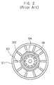
- the magnetron also includes a large-diameter strip ring 104 and a small-diameter strip ring 105 disposed on upper and lower portions of the vanes 102, respectively, to alternately and electrically connect the vanes 102 so that the vanes 102 alternately have the same electric potential as shown in Figure 2.
- Rectangular depressions 202 are formed in the vanes 102, respectively, to allow the strip rings 104 and 105 to alternately and electrically connect the vanes 102, and cause each opposite pair of the vanes 102 to be disposed in an inverted manner.
- each of the pair of opposite vanes 102 and the positive polar cylinder 101 constitute a certain LC resonant circuit.
- a filament 106 in a form of a coil spring is disposed in an axial center portion of the positive polar cylinder 101, and an activating space 107 is provided between radially inside ends of the vanes 102 and the filament 106.
- An upper shield 108 and a lower shield 109 are attached to a top and bottom of the filament 106, respectively.
- a center lead 110 is welded to a bottom of the upper shield 108 while being passed through a through hole of the lower shield 109 and the filament 106.
- a side lead 111 is welded to a bottom of the lower shield 109.
- the center lead 110 and the side lead 111 are connected to terminals of an external power source (not shown), and therefore, forms a closed circuit in the magnetron.
- An upper permanent magnet 112 and a lower permanent magnet 113 are provided to apply a magnetic field to the activating space 107 with opposite magnetic poles of the upper and lower permanent magnets 112 and 113 facing each other.
- An upper pole piece 117 and a lower pole piece 118 are provided to induce rotating magnetic flux generated by the permanent magnets 112 and 113 into the activating space 107.
- the above-described elements are enclosed in an upper yoke 114 and a lower yoke 115. Cooling fins 116 connect the positive polar cylinder 101 to the lower yoke 115, and radiate heat generated in the positive polar cylinder 101 to the outside through the lower yoke 115.
- the filament 106 when power is applied to the filament 106 from the external power source, the filament 106 is heated by operational current supplied to the filament 106, the thermions are emitted from the filament 106, and a group of thermions 301 are produced in the activating space 107 by the emitted thermions as shown in Figure 3.
- the group of thermions 301 alternately imparts potential difference to each neighboring pair of the vanes 102 while being in contact with front ends of the vanes 102, being rotated by influence of the magnetic field formed in the activating space 107, and being moved from one state "i" to another state "f". Accordingly, harmonics corresponding to a rotation speed of the thermion group 301 are generated by oscillation of the LC resonant circuit formed by the vanes 102 and the positive polar cylinder 101, and transmitted to the outside through the antenna 103.
- the depressions 202 are formed to allow the strip rings to be disposed therein.
- the depressions 202 are constructed to have regular rectangular shapes corresponding to the rectangular cross-section of the strip rings.
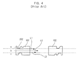
- arrows L1, L2 and L3 represent distances along which the thermions travel from one of the vanes 102 to the neighboring vane 102.
- the thermions at the sections “a” and “c” travel along the same distance at the same time.
- a main frequency of the magnetron is generally determined by the sections “b” of the vanes 102. Therefore, the delays in the thermions reaching the sections “a” and “b” of the neighboring vane 102 cause noise in all the frequencies of the magnetron.
- a magnetron for microwave ovens including a positive polar cylinder, a cathode, and a plurality of vanes to constitute a positive polar section along with the positive polar cylinder.
- Each of the vanes is provided with a first depression to allow a large-diameter strip ring to be disposed therein, and a second depression to allow a small-diameter strip ring to be disposed therein.
- the vane is provided at a cathode-side corner of the first depression with a thermion travel passage to allow thermions to smoothly flow without hindrance of the first depression.
- the thermion travel passage is formed by a protrusion formed to fill the cathode-side corner of the first depression.
- the protrusion may have a rectangular shape; a shape of a right-triangle with a concave hypotenuse; a quarter-circular shape; or a right-triangular shape, amongst many other suitable variations.
- the protrusion may be made of solder material.
- each vane is provided with at least one rectangular protrusion.
- each vane is provided with at least one rectangular protrusion formed at a top and a bottom of the vane, preferably in a corner of a depression.
- These rectangular protrusions allow thermions to smoothly flow without hindrance of the depressions, thereby reducing an occurrence of noise in the magnetron.
- the thermions travel from one of the vanes to another vane with similar velocities, so that a frequency generated in the magnetron is stabilised.
- a magnetron for microwave ovens comprising: a positive polar cylinder; a cathode; and a plurality of vanes to constitute a positive polar section along with the positive polar cylinder, wherein rectangular protrusions are provided at depression of the vanes to form a thermion travel passage, thereby allowing thermions to smoothly flow from one of the vanes to another vane.
- a resultant force F -e ( E + ⁇ B ) made of a horizontal force and vertical force is formed by a magnetic force that is produced in the activating space by permanent magnets disposed in upper and lower portions of the magnetron under influence of movement of the thermions.
- F is a resultant force
- -e is a quantity of electric charge
- E is an intensity of an electric field between a filament and vanes
- ⁇ is a velocity of thermions
- B is an intensity of a magnetic field produced by permanent magnets.
- FIG. 5 A pair of neighboring vanes 500a and 500b according to an embodiment of the present invention is now described with reference to Figure 5.
- the pair of neighboring vanes 500a and 500b is illustrated as being opposite to each other for convenience of explanation.
- the vane 500a is in a geometrically symmetric relationship with the vane 500b in that they are not symmetrical on a plane but are symmetrical in an inverted relationship.
- a rectangular protrusion 502a is formed to partially connect a cathode side 506 and bottom 507 of the depression 501a to each other at a corner of the cathode side 506 of the depression 501a, so that the depression 501a has a stepped shape.
- a group of thermions which is formed in an activating space as shown in Figure 3, causes the pair of neighboring vanes 500a and 500b to have an electric phase difference of 180° therebetween in ⁇ -mode. Accordingly, when the thermions arrive at a front of a random vane, for example, 500a, an electric phase difference of 180° (that is, a certain potential difference) is generated between the vane 500a and another vane, for example, 500b, opposite vane 500a, thus inducing a flow of current due to a movement of the thermions.
- thermions arrive at the front side of the vane 500a with the front side divided into sections "A,” “B” and “C”.
- the thermions departing from the front side of the vane 500a are moved toward the front side of the vane 500b.
- a velocity of the thermions is closely related to a frequency of microwaves emitted to an outside.
- the movement of thermions does not require a roundabout path because the thermions are moved almost straight to the neighboring vane 500b through the rectangular protrusion 502a without hindrance of the depression 501a formed on the vane 500a.
- the rectangular depression 501a provides the thermions with an almost straight travel path
- the rectangular protrusion 502a functions as a thermion travel passage to allow the thermions arriving at the section "A" to be smoothly moved to the neighboring vane 500b.
- differences between distances (“La,” “Lb,” and “Lc”), along which the thermions travel to sections “A,” “B” and “C”, per time, that is, differences between the velocities of thermions are significantly reduced or eliminated.
- the fact that the differences between the velocities of the thermions are significantly reduced or eliminated means that parasitic frequencies included in a main frequency are reduced or eliminated. In turn, this also means that an occurrence of high frequency noise reduced and thus, efficiency of the magnetron is improved.
- the rectangular protrusion 502a is formed at the corner of the cathode side of the depression 501a to keep thermions from taking a roundabout path. Consequently, the thermions arriving at the section "A" are allowed to have a velocity identical with or similar to that of the thermions arriving at the section "B", so the same frequency is generated in a resonant circuit composed of the vanes 500a and 500b and a positive polar cylinder, thus improving quality of the magnetron.
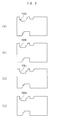
- Figures 6A through 6D are diagrams of a variety of vanes, according to various embodiments of the present invention.
- a vane is provided with a rectangular protrusion 602a at a cathode-side corner of its upper depression.
- a vane is provided with a right-triangular protrusion 602b having a concave hypotenuse at the cathode-side corner of its upper depression.
- a vane is provided with a quarter-circular protrusion 602c at the cathode-side corner of its upper depression.
- a vane is provided with a right-triangular protrusion 602d at the cathode-side corner of its upper depression.
- vanes according to the various embodiments of the present invention are somewhat different from one another in geometrical configuration, but have the same or similar effect.
- each of them is provided with a protrusion at the cathode-side corner of its upper depression, which is used to allow a large-diameter strip ring to be disposed therein, to prevent thermions from flowing along a roundabout path.
- the protrusions 602a, 602b,602c and 602d have been described as an extension of the vanes and thus, made of the same material as the vanes, the protrusions may be made of materials having high conductivity, such as solder.
- the present invention provides a magnetron equipped with a plurality of vanes, which is capable of preventing thermions from flowing along roundabout paths. Therefore, the magnetron of the present invention reduces the difference between the velocities of thermions and equalizes the velocities of thermions, thereby reducing unwanted noise and improving the efficiency of the magnetron.
Landscapes
- Microwave Tubes (AREA)
Abstract
A magnetron for microwave ovens includes a positive
polar cylinder (101), a cathode (106), and a plurality of
vanes (500). The vanes (500) constitute a positive polar
section along with the positive polar cylinder (101). Each of
the vanes (500) is provided with at least one depression,
preferably a first depression (501a) to allow a large-diameter
strip ring (104) to be disposed therein, and a second
depression (501b) to allow a small-diameter strip ring (105) to
be disposed therein. Each vane (500) is provided, suitably at a
cathode-side corner of the first depression (501a), with a
thermion travel passage to allow thermions to smoothly
flow without the hindrance of the first depression (501a). The
thermion travel passage is suitably a protrusion (502a)
that fills the corner of the depression (501a).
Description
- The present invention relates generally to a magnetron for microwave ovens, and more particularly, to a vane of a magnetron for microwave ovens.
- Generally, a magnetron is constructed to have an anode and a cathode such that thermions are discharged from the cathode and spirally moved to the anode by electromagnetic force. A spinning electron pole is generated around the cathode by the thermions and current is induced in an oscillation circuit of the anode, so that oscillation is continuously stimulated. An oscillation frequency of the magnetron is generally determined by the oscillation circuit, and has high efficiency and high output power. The magnetron is widely used in home appliances, such as microwave ovens, as well as in industrial applications, such as high-frequency heating apparatuses, particle accelerators and radar systems.
- The general construction and operation of the above-described magnetron are briefly described with reference to Figures 1 through 3.
- As shown in Figure 1, the magnetron generally includes a positive
polar cylinder 101 made of an oxygen free copper pipe or the like, a plurality ofvanes 102 disposed in the positivepolar cylinder 101 to constitute a positive polar section along with the positivepolar cylinder 101 and radially arranged at regular intervals to form a cavity resonator, and anantenna 103 connected to one of thevanes 102 to induce harmonics to an outside. The magnetron also includes a large-diameter strip ring 104 and a small-diameter strip ring 105 disposed on upper and lower portions of thevanes 102, respectively, to alternately and electrically connect thevanes 102 so that thevanes 102 alternately have the same electric potential as shown in Figure 2. -
Rectangular depressions 202 are formed in thevanes 102, respectively, to allow thestrip rings vanes 102, and cause each opposite pair of thevanes 102 to be disposed in an inverted manner. According to the above-described construction, each of the pair ofopposite vanes 102 and the positivepolar cylinder 101 constitute a certain LC resonant circuit. Additionally, afilament 106 in a form of a coil spring is disposed in an axial center portion of the positivepolar cylinder 101, and an activatingspace 107 is provided between radially inside ends of thevanes 102 and thefilament 106. Anupper shield 108 and alower shield 109 are attached to a top and bottom of thefilament 106, respectively. Acenter lead 110 is welded to a bottom of theupper shield 108 while being passed through a through hole of thelower shield 109 and thefilament 106. Aside lead 111 is welded to a bottom of thelower shield 109. Thecenter lead 110 and theside lead 111 are connected to terminals of an external power source (not shown), and therefore, forms a closed circuit in the magnetron. - An upper
permanent magnet 112 and a lowerpermanent magnet 113 are provided to apply a magnetic field to the activatingspace 107 with opposite magnetic poles of the upper and lowerpermanent magnets permanent magnets space 107. The above-described elements are enclosed in anupper yoke 114 and alower yoke 115.Cooling fins 116 connect the positivepolar cylinder 101 to thelower yoke 115, and radiate heat generated in the positivepolar cylinder 101 to the outside through thelower yoke 115. - According to the above-described construction of the magnetron, when power is applied to the
filament 106 from the external power source, thefilament 106 is heated by operational current supplied to thefilament 106, the thermions are emitted from thefilament 106, and a group ofthermions 301 are produced in the activatingspace 107 by the emitted thermions as shown in Figure 3. The group ofthermions 301 alternately imparts potential difference to each neighboring pair of thevanes 102 while being in contact with front ends of thevanes 102, being rotated by influence of the magnetic field formed in the activatingspace 107, and being moved from one state "i" to another state "f". Accordingly, harmonics corresponding to a rotation speed of thethermion group 301 are generated by oscillation of the LC resonant circuit formed by thevanes 102 and the positivepolar cylinder 101, and transmitted to the outside through theantenna 103. - Generally, frequency is calculated by an equation
vanes 102 constituting part of the LC resonant circuit are principal factors in determining the frequency of harmonics. - In the magnetron having the above-described construction and operation, noise of a considerably wide band considered as unwanted electromagnetic waves is generated. The noise may induce malfunction in other devices. Thus, a reduction in the noise is an important technical issue that has been researched for a long time. In this regard, the geometrical configuration of the vane, which is one of factors that determine a frequency of electromagnetic waves generated in the magnetron, is an important technical issue relative to the generation of noise.
- Conventional vanes constituting parts of the magnetron are constructed as shown in Figure 4. The shortcomings of the conventional vanes are described with reference to Figure 4. As shown in Figure 4, a pair of neighboring vanes is illustrated as being opposite to each other for convenience of explanation.
- As shown in Figure 3, the
depressions 202 are formed to allow the strip rings to be disposed therein. In Figure 4, thedepressions 202 are constructed to have regular rectangular shapes corresponding to the rectangular cross-section of the strip rings. After the thermions arrive at sections "a," "b" and "c" of the front side of avane 102, the thermions arriving at the section "a" are moved to the section "c" of the front side of another neighboringvane 102 because of the inverted relationship of the pair of neighboringvanes 202. As the thermions arrive at the front side of thevane 102, a potential difference is generated between the pair of neighboringvanes 102 and, current (that is, the flow of thermions) is supplied to thefilament 106. The thermions arriving at the sections "a" and "c" are moved to the sections "c" and "a" of the front side of the neighboringvane 102 along roundabout paths due to a hindrance effect of thedepressions 202, thus resulting in delaying the arrival of the thermions at the section "b" of the front side of the neighboringvane 102 in comparison with the arrival of the sections "a" and "c". - In Figure 4, arrows L1, L2 and L3 represent distances along which the thermions travel from one of the
vanes 102 to the neighboringvane 102. The thermions at the sections "a" and "c" travel along the same distance at the same time. A main frequency of the magnetron is generally determined by the sections "b" of thevanes 102. Therefore, the delays in the thermions reaching the sections "a" and "b" of the neighboringvane 102 cause noise in all the frequencies of the magnetron. - It is an aim of the present invention to provide a magnetron for microwave ovens to reduce high frequency noise caused by a difference between velocities of thermions flowing through vanes of the magnetron, thus optimizing frequency of microwaves emitted from the magnetron.
- Additional aims and advantages of the invention will be set forth in part in the description which follows and, in part, will be obvious from the description, or may be learned by practice of the invention.
- According to the present invention there is provided an apparatus and method as set forth in the appended claims. Preferred features of the invention will be apparent from the dependent claims and the description which follows.
- In one aspect of the present invention there is provided a magnetron for microwave ovens, including a positive polar cylinder, a cathode, and a plurality of vanes to constitute a positive polar section along with the positive polar cylinder. Each of the vanes is provided with a first depression to allow a large-diameter strip ring to be disposed therein, and a second depression to allow a small-diameter strip ring to be disposed therein. Also, the vane is provided at a cathode-side corner of the first depression with a thermion travel passage to allow thermions to smoothly flow without hindrance of the first depression.
- Preferably, the thermion travel passage is formed by a protrusion formed to fill the cathode-side corner of the first depression.
- The protrusion may have a rectangular shape; a shape of a right-triangle with a concave hypotenuse; a quarter-circular shape; or a right-triangular shape, amongst many other suitable variations. The protrusion may be made of solder material.
- Preferably, each vane is provided with at least one rectangular protrusion. Ideally, each vane is provided with at least one rectangular protrusion formed at a top and a bottom of the vane, preferably in a corner of a depression. These rectangular protrusions allow thermions to smoothly flow without hindrance of the depressions, thereby reducing an occurrence of noise in the magnetron. Also, the thermions travel from one of the vanes to another vane with similar velocities, so that a frequency generated in the magnetron is stabilised.
- According to a second aspect of the present invention there is provided a magnetron for microwave ovens, comprising: a positive polar cylinder; a cathode; and a plurality of vanes to constitute a positive polar section along with the positive polar cylinder, wherein rectangular protrusions are provided at depression of the vanes to form a thermion travel passage, thereby allowing thermions to smoothly flow from one of the vanes to another vane.
- For a better understanding of the invention, and to show how embodiments of the same may be carried into effect, reference will now be made, by way of example, to the accompanying diagrammatic drawings in which:
- Figure 1 is a longitudinal section of a conventional magnetron for microwave ovens;
- Figure 2 is a cross section of a polar section of Figure 1;
- Figure 3 is a cross section showing a formation of thermions of the polar section shown in Figure 2;
- Figure 4 is a side view showing conventional vanes and a flow of thermions therethrough;
- Figure 5 is a side view showing vanes and a flow of thermions therethrough, according to an embodiment of the present invention; and
- Figures 6A through 6D are diagrams of a variety of vanes, according to various embodiments of the present invention.
-
- When an external power source is applied to a magnetron, heat is continuously generated in a filament composed of a mixture of tungsten and thorium oxide. Thermions excited by the heat deviate from a potential well and escape from the filament. Since the thermions are emitted from the filament through an entire surface of the filament, a group of thermions exist in an activating space formed between the filament and vanes. The group of thermions are moved toward the vanes by an action of an electric field produced between the filament and the vanes. A resultant force F = -e(E + υB) made of a horizontal force and vertical force is formed by a magnetic force that is produced in the activating space by permanent magnets disposed in upper and lower portions of the magnetron under influence of movement of the thermions. In the above equation, F is a resultant force, -e is a quantity of electric charge, E is an intensity of an electric field between a filament and vanes, υ is a velocity of thermions, and B is an intensity of a magnetic field produced by permanent magnets. Additionally, since groups of thermions are continuously emitted from the filament, there occurs a phenomenon in which the groups of thermions are continuously moved to the vanes.
- Much of the above description of the construction and operation of a conventional magnetron with reference to Figures 1 to 3 is also relevant to the preferred embodiment of the present invention and need not be repeated here. A pair of neighboring
vanes vanes - As shown in Figure 5, the
vane 500a is in a geometrically symmetric relationship with thevane 500b in that they are not symmetrical on a plane but are symmetrical in an inverted relationship. - A
rectangular protrusion 502a is formed to partially connect acathode side 506 andbottom 507 of thedepression 501a to each other at a corner of thecathode side 506 of thedepression 501a, so that thedepression 501a has a stepped shape. Arectangular protrusion 504 constructed similarly to therectangular protrusion 502a, and formed at the corner of thedepression 501a opposite to the corner at which therectangular protrusion 502a is formed, and anotherrectangular protrusion 505 constructed similarly to therectangular protrusion 502a and formed at a corner of a cathode side of adepression 501b, each have an object of alternately connecting strip rings to thevanes - The operation of the vane of the magnetron according to the preferred embodiment of the present invention is described below.
- A group of thermions, which is formed in an activating space as shown in Figure 3, causes the pair of neighboring
vanes vane 500a and another vane, for example, 500b,opposite vane 500a, thus inducing a flow of current due to a movement of the thermions. - For convenience of explanation, there is described a case where thermions arrive at the front side of the
vane 500a with the front side divided into sections "A," "B" and "C". The thermions departing from the front side of thevane 500a are moved toward the front side of thevane 500b. A velocity of the thermions is closely related to a frequency of microwaves emitted to an outside. In the present invention, the movement of thermions does not require a roundabout path because the thermions are moved almost straight to the neighboringvane 500b through therectangular protrusion 502a without hindrance of thedepression 501a formed on thevane 500a. Thus, therectangular depression 501a provides the thermions with an almost straight travel path, and therectangular protrusion 502a functions as a thermion travel passage to allow the thermions arriving at the section "A" to be smoothly moved to the neighboringvane 500b. - Accordingly, differences between distances ("La," "Lb," and "Lc"), along which the thermions travel to sections "A," "B" and "C", per time, (that is, differences between the velocities of thermions) are significantly reduced or eliminated. The fact that the differences between the velocities of the thermions are significantly reduced or eliminated means that parasitic frequencies included in a main frequency are reduced or eliminated. In turn, this also means that an occurrence of high frequency noise reduced and thus, efficiency of the magnetron is improved.
- As a result, the
rectangular protrusion 502a is formed at the corner of the cathode side of thedepression 501a to keep thermions from taking a roundabout path. Consequently, the thermions arriving at the section "A" are allowed to have a velocity identical with or similar to that of the thermions arriving at the section "B", so the same frequency is generated in a resonant circuit composed of thevanes - Figures 6A through 6D are diagrams of a variety of vanes, according to various embodiments of the present invention. In Figure 6A, a vane is provided with a rectangular protrusion 602a at a cathode-side corner of its upper depression. In Figure 6B, a vane is provided with a right-triangular protrusion 602b having a concave hypotenuse at the cathode-side corner of its upper depression. In Figure 6C, a vane is provided with a quarter-circular protrusion 602c at the cathode-side corner of its upper depression. In Figure 6D, a vane is provided with a right-triangular protrusion 602d at the cathode-side corner of its upper depression. The vanes according to the various embodiments of the present invention are somewhat different from one another in geometrical configuration, but have the same or similar effect. Thus, each of them is provided with a protrusion at the cathode-side corner of its upper depression, which is used to allow a large-diameter strip ring to be disposed therein, to prevent thermions from flowing along a roundabout path.
- Although in the above-described embodiments the protrusions 602a, 602b,602c and 602d have been described as an extension of the vanes and thus, made of the same material as the vanes, the protrusions may be made of materials having high conductivity, such as solder.
- As described in detail above, the present invention provides a magnetron equipped with a plurality of vanes, which is capable of preventing thermions from flowing along roundabout paths. Therefore, the magnetron of the present invention reduces the difference between the velocities of thermions and equalizes the velocities of thermions, thereby reducing unwanted noise and improving the efficiency of the magnetron.
- Although a few preferred embodiments of the present invention have been shown and described, it would be appreciated by those skilled in the art that changes may be made in these embodiments without departing from the scope of the invention, as defined in the claims.
- Attention is directed to all papers and documents which are filed concurrently with or previous to this specification in connection with this application and which are open to public inspection with this specification, and the contents of all such papers and documents are incorporated herein by reference.
- All of the features disclosed in this specification (including any accompanying claims, abstract and drawings), and/or all of the steps of any method or process so disclosed, may be combined in any combination, except combinations where at least some of such features and/or steps are mutually exclusive.
- Each feature disclosed in this specification (including any accompanying claims, abstract and drawings) may be replaced by alternative features serving the same, equivalent or similar purpose, unless expressly stated otherwise. Thus, unless expressly stated otherwise, each feature disclosed is one example only of a generic series of equivalent or similar features.
- The invention is not restricted to the details of the foregoing embodiment(s). The invention extends to any novel one, or any novel combination, of the features disclosed in this specification (including any accompanying claims, abstract and drawings), or to any novel one, or any novel combination, of the steps of any method or process so disclosed.
Claims (15)
- A magnetron for microwave ovens, comprising:wherein at least one vane (102) is provided at a corner of a first depression (501a) with a thermion travel passage (502a) to allow thermions to smoothly flow without hindrance of the first depression (501a).a positive polar cylinder (101);a cathode (106); anda plurality of vanes (500) to constitute a positive polar section along with the positive polar cylinder, each of the vanes being provided with at least one depression (501a,501b) to allow a strip ring (104,105) to be disposed therein;
- The magnetron of claim 1, wherein the thermion travel passage (502a) is provided at a cathode-side corner of the first depression (501a).
- The magnetron of claim 1 or 2, wherein the first depression (501a) is arranged to receive a large diameter strip ring (104) and each vane comprises a second depression (501b) arranged to receive a small diameter strip ring (105).
- The magnetron of claim 3, wherein the first depression and the second depression (501a,501b) each comprise at least one thermion travel passage (502a,504,505).
- The magnetron according to any preceding claim, wherein the or each thermion travel passage is formed by a protrusion (502a,504,505) formed to fill the corner of the depression (501a,501b).
- The magnetron according to claim 5, wherein the or each protrusion (502a,504,505) has any of:a rectangular shape;a shape of a right-triangle with a concave hypotenuse;a quarter-circular shape; and/ora right-triangular shape.
- The magnetron according to claim 5 or 6, wherein any of the protrusions (502a,504,505) are made of a solder material.
- The magnetron according to any preceding claim, wherein each vane (102) is provided with at least one rectangular protrusion (502a, 504, 505).
- The magnetron according to any preceding claim, wherein each vane (102) is provided with at least one rectangular protrusion (502a,505) formed at a top and bottom of the vane.
- The magnetron according to any preceding claim, wherein a rectangular protrusion (502a) is provided at the first depression (501a) to allow thermions to smoothly flow without hindrance of the first depression, thereby reducing an occurrence of noise in the magnetron.
- The magnetron according to claim 10, wherein the rectangular protrusion (502a) is formed at the cathode-side corner to form the thermion travel passage, thereby keeping the thermions from taking a path around the vane.
- The magnetron according to any preceding claim, wherein the thermions travel from one of the vanes (102) to another vane with similar velocities so that a frequency generated in the magnetron is stabilized.
- A magnetron for microwave ovens, comprising:wherein at least one protrusion (502a,504,505) is provided at a depression (501a,501b) of the vanes to form a thermion travel passage, thereby allowing thermions to smoothly flow from one of the vanes to another vane.a positive polar cylinder (101);a cathode (106); anda plurality of vanes (500) to constitute a positive polar section along with the positive polar cylinder,
- The magnetron of claim 13, wherein the protrusions (502a,504,505) in use allow thermions to smoothly flow around the depression (501a,501b).
- The magnetron of claim 13 or 14, wherein the depressions (501a,501b) are arranged in use to receive strip rings (104,105).
Applications Claiming Priority (2)
| Application Number | Priority Date | Filing Date | Title |
|---|---|---|---|
| KR2002046167 | 2002-08-05 | ||
| KR1020020046167A KR20040013307A (en) | 2002-08-05 | 2002-08-05 | Magnetron |
Publications (1)
| Publication Number | Publication Date |
|---|---|
| EP1388880A2 true EP1388880A2 (en) | 2004-02-11 |
Family
ID=30439417
Family Applications (1)
| Application Number | Title | Priority Date | Filing Date |
|---|---|---|---|
| EP02258854A Withdrawn EP1388880A2 (en) | 2002-08-05 | 2002-12-23 | Magnetron for microwave ovens |
Country Status (5)
| Country | Link |
|---|---|
| US (1) | US6693378B1 (en) |
| EP (1) | EP1388880A2 (en) |
| JP (1) | JP2004071531A (en) |
| KR (1) | KR20040013307A (en) |
| CN (1) | CN1474429A (en) |
Families Citing this family (3)
| Publication number | Priority date | Publication date | Assignee | Title |
|---|---|---|---|---|
| KR100700554B1 (en) * | 2005-12-30 | 2007-03-28 | 엘지전자 주식회사 | magnetron |
| EP2962322A4 (en) * | 2013-03-01 | 2016-10-26 | Soo Yong Park | Magnetron |
| CN110379692B (en) * | 2019-08-19 | 2024-01-26 | 电子科技大学 | Flattened magnetron for microwave oven adopting symmetrical magnetic circuit |
Family Cites Families (11)
| Publication number | Priority date | Publication date | Assignee | Title |
|---|---|---|---|---|
| JPS60160542A (en) * | 1984-02-01 | 1985-08-22 | Hitachi Ltd | Manufacturing method of magnetron anode structure |
| DE3673587D1 (en) * | 1985-09-09 | 1990-09-27 | Toshiba Kawasaki Kk | MAGNETRONANODE AND THEIR PRODUCTION. |
| JPS62223946A (en) * | 1986-03-26 | 1987-10-01 | Hitachi Ltd | Magnetron anode structure |
| JP2594262B2 (en) * | 1986-10-16 | 1997-03-26 | 松下電器産業株式会社 | Magnetron |
| KR930000778Y1 (en) * | 1987-09-24 | 1993-02-25 | 주식회사 금성사 | Magnetron Anodized Bain |
| US5146136A (en) * | 1988-12-19 | 1992-09-08 | Hitachi, Ltd. | Magnetron having identically shaped strap rings separated by a gap and connecting alternate anode vane groups |
| JPH05342997A (en) * | 1992-06-10 | 1993-12-24 | Hitachi Ltd | Anode structural body of magnetron |
| KR0116002Y1 (en) * | 1994-07-18 | 1998-04-17 | 배순훈 | Vein with soldering groove |
| KR100188605B1 (en) | 1996-08-30 | 1999-06-01 | 전주범 | The structure of vane of magnetron for harmonic frequency stability |
| KR200152142Y1 (en) | 1997-02-06 | 1999-07-15 | 윤종용 | Magnetron vane |
| US6222319B1 (en) * | 1997-04-11 | 2001-04-24 | Matsushita Electronics Corporation | Magnetron apparatus having a segmented anode edges and manufacturing method |
-
2002
- 2002-08-05 KR KR1020020046167A patent/KR20040013307A/en not_active Ceased
- 2002-11-29 US US10/306,856 patent/US6693378B1/en not_active Expired - Fee Related
- 2002-12-16 JP JP2002364264A patent/JP2004071531A/en active Pending
- 2002-12-23 CN CNA021584117A patent/CN1474429A/en active Pending
- 2002-12-23 EP EP02258854A patent/EP1388880A2/en not_active Withdrawn
Also Published As
| Publication number | Publication date |
|---|---|
| US6693378B1 (en) | 2004-02-17 |
| CN1474429A (en) | 2004-02-11 |
| JP2004071531A (en) | 2004-03-04 |
| KR20040013307A (en) | 2004-02-14 |
| US20040021421A1 (en) | 2004-02-05 |
Similar Documents
| Publication | Publication Date | Title |
|---|---|---|
| EP1870923B1 (en) | Magnetron | |
| EP1388880A2 (en) | Magnetron for microwave ovens | |
| TW200303121A (en) | Phased array source of electromagnetic radiation | |
| EP1482531B1 (en) | Magnetron | |
| EP1429365A2 (en) | Magnetron, and microwave oven and high-frequency heating apparatus each equipped with the same | |
| EP1388879A2 (en) | Magnetron | |
| US6867405B2 (en) | Magnetron for microwave ovens | |
| RU2263376C1 (en) | Slow-wave structure of traveling-wave tube | |
| US6759639B2 (en) | Magnetron for microwave ovens | |
| KR100539815B1 (en) | Magnetron gasket ring coupling structure | |
| KR100519265B1 (en) | Magnetron | |
| KR100455195B1 (en) | Magnetic focusing structure of magnetron | |
| KR200162643Y1 (en) | Magnetron | |
| KR100556946B1 (en) | Magnetron Stimulation Structure | |
| KR19980062075U (en) | magnetron | |
| JP2001060440A (en) | Magnetron | |
| KR20040013310A (en) | Magnetron | |
| KR20030089322A (en) | Yoke structure for magnetron | |
| KR19980062077U (en) | magnetron | |
| KR20040110568A (en) | Yoke structure of magnetron | |
| KR19980058948U (en) | magnetron | |
| KR20040061408A (en) | Cooling pin assembly structure of magnetron |
Legal Events
| Date | Code | Title | Description |
|---|---|---|---|
| PUAI | Public reference made under article 153(3) epc to a published international application that has entered the european phase |
Free format text: ORIGINAL CODE: 0009012 |
|
| 17P | Request for examination filed |
Effective date: 20030113 |
|
| AK | Designated contracting states |
Kind code of ref document: A2 Designated state(s): AT BE BG CH CY CZ DE DK EE ES FI FR GB GR IE IT LI LU MC NL PT SE SI SK TR |
|
| AX | Request for extension of the european patent |
Extension state: AL LT LV MK RO |
|
| STAA | Information on the status of an ep patent application or granted ep patent |
Free format text: STATUS: THE APPLICATION HAS BEEN WITHDRAWN |
|
| 18W | Application withdrawn |
Effective date: 20041014 |