EP1388718A1 - Bidirectional receiver dryer - Google Patents
Bidirectional receiver dryer Download PDFInfo
- Publication number
- EP1388718A1 EP1388718A1 EP03102266A EP03102266A EP1388718A1 EP 1388718 A1 EP1388718 A1 EP 1388718A1 EP 03102266 A EP03102266 A EP 03102266A EP 03102266 A EP03102266 A EP 03102266A EP 1388718 A1 EP1388718 A1 EP 1388718A1
- Authority
- EP
- European Patent Office
- Prior art keywords
- receiver dryer
- refrigerant
- drying chamber
- expansion device
- drying
- Prior art date
- Legal status (The legal status is an assumption and is not a legal conclusion. Google has not performed a legal analysis and makes no representation as to the accuracy of the status listed.)
- Granted
Links
Images


Classifications
-
- F—MECHANICAL ENGINEERING; LIGHTING; HEATING; WEAPONS; BLASTING
- F25—REFRIGERATION OR COOLING; COMBINED HEATING AND REFRIGERATION SYSTEMS; HEAT PUMP SYSTEMS; MANUFACTURE OR STORAGE OF ICE; LIQUEFACTION SOLIDIFICATION OF GASES
- F25B—REFRIGERATION MACHINES, PLANTS OR SYSTEMS; COMBINED HEATING AND REFRIGERATION SYSTEMS; HEAT PUMP SYSTEMS
- F25B43/00—Arrangements for separating or purifying gases or liquids; Arrangements for vaporising the residuum of liquid refrigerant, e.g. by heat
- F25B43/003—Filters
-
- F—MECHANICAL ENGINEERING; LIGHTING; HEATING; WEAPONS; BLASTING
- F25—REFRIGERATION OR COOLING; COMBINED HEATING AND REFRIGERATION SYSTEMS; HEAT PUMP SYSTEMS; MANUFACTURE OR STORAGE OF ICE; LIQUEFACTION SOLIDIFICATION OF GASES
- F25B—REFRIGERATION MACHINES, PLANTS OR SYSTEMS; COMBINED HEATING AND REFRIGERATION SYSTEMS; HEAT PUMP SYSTEMS
- F25B13/00—Compression machines, plants or systems, with reversible cycle
-
- F—MECHANICAL ENGINEERING; LIGHTING; HEATING; WEAPONS; BLASTING
- F25—REFRIGERATION OR COOLING; COMBINED HEATING AND REFRIGERATION SYSTEMS; HEAT PUMP SYSTEMS; MANUFACTURE OR STORAGE OF ICE; LIQUEFACTION SOLIDIFICATION OF GASES
- F25B—REFRIGERATION MACHINES, PLANTS OR SYSTEMS; COMBINED HEATING AND REFRIGERATION SYSTEMS; HEAT PUMP SYSTEMS
- F25B2400/00—Component parts or details not otherwise provided for in this subclass
- F25B2400/16—Receivers
Definitions
- the present invention generally relates to a bidirectional receiver dryer, in particular for use in a reversible air conditioning system.
- a refrigerant in a vapor state is compressed by a compressor unit driven by a motor.
- the compressed refrigerant at high temperature and pressure, enters a condenser where heat is removed from the compressed refrigerant and the refrigerant changes to a liquid state.
- the refrigerant then travels through a receiver dryer to an expansion device.
- the expansion device throttles the refrigerant as the refrigerant flows through an orifice, which causes the refrigerant to change phase from liquid to a saturated liquid/vapor mixture.
- the mixture then enters an evaporator, where heat is drawn from the environment, thus cooling the environmental air and causing the refrigerant to change to a vapor state.
- the low-pressure refrigerant flow from the evaporator returns to the suction side of the compressor to begin the cycle anew.
- Receiver dryer devices in particular for use in automobile air conditioning units, are well known in the state of the art. They are generally located between the condenser and the expansion device and ensure that only liquid refrigerant is fed to the expansion device.
- the internal combustion engine cannot be relied upon to provide the heat necessary for heating the passenger compartment of the vehicle in cold climate conditions. It has therefore been proposed to operate the air conditioning system as a heat pump, by reversing the flow of refrigerant.
- a reversing valve can be provided and the flow is diverted such that the original evaporator becomes the condenser, the original condenser becomes the evaporator and the flow of refrigerant through the system is reversed.
- a further receiver dryer device must be provided on the other side of the expansion device. This further receiver dryer unfortunately uses up valuable space and the whole system becomes heavier and more expensive.
- Such a receiver dryer has been disclosed in US-5,832,741 to Hutchison at al.
- This receiver dryer comprises a drying chamber for removing moisture from the refrigerant and a bypass chamber for bypassing the drying chamber.
- the receiver dryer further comprises four ports, two circuit ports and two expansion device ports.
- the two circuit ports are connected to the evaporator and condenser respectively and the two expansion device ports are connected to the expansion device.
- the refrigerant first flows via one of the circuit ports into the drying chamber of the receiver dryer, where it passes through the desiccant material and moisture is removed from the refrigerant.
- the refrigerant is then led via the first of the expansion device ports out of the receiver dryer and to the expansion device, where it expands.
- the refrigerant is then led from the expansion device into the bypass chamber of the receiver dryer via the second of the expansion device ports.
- the refrigerant finally leaves the receiver dryer via the other of the circuit ports.
- the flow of refrigerant within the receiver dryer is controlled by means of a rather complex arrangement of check valves.
- Four ball valves are arranged between the two circuit ports to direct the flow of refrigerant either through the drying chamber or through the bypass chamber. This complex arrangement of check valves makes the receiver dryer rather difficult to assemble and therefore also more expensive.
- the object of the present invention is to provide a bidirectional receiver dryer of simpler design.
- a bidirectional receiver dryer comprises a housing, a first drying chamber and a second drying chamber within the housing, a partition wall arranged in the housing for separating the first and second drying chambers, and an expansion device fluidly connected between the first and second drying chambers.
- the partition wall is arranged so as to be able to increase the size of one of the drying chambers while at the same time decreasing the size of the other drying chamber, one of the drying chambers having its size increased at the expense of the other.
- the receiver dryer according to the invention has one drying chamber arranged either side of the expansion device. Whichever mode the air conditioning system is operated in, the refrigerant always flows through one drying chamber, through the expansion device and then through the other drying chamber. There is therefore no need to provide the receiver dryer with any check valves to direct the flow of refrigerant through the receiver dryer.
- the present receiver dryer is therefore simpler in design and can be more cheaply produced.
- the absence of check valves also increases the reliability of the receiver dryer as there are fewer elements that can break down.
- the partition wall allows the drying chambers to be adapted in size and that one of the drying chambers has its size increased at the expense of the other, a more compact receiver dryer can be achieved. While the drying chamber upstream of the expansion device needs to have a certain size in order to be able to receive the refrigerant therein, the drying chamber downstream of the expansion device can be considerably smaller. Instead of arranging two drying chambers of certain size in the receiver dryer, the present invention proposes to provide a partition wall, which allows the drying chambers to vary in size. As the size of the drying chamber upstream of the expansion device is increased, the size of the other drying chamber is decreased by approximately the same amount.
- a first of the drying chambers is increased in size so as to receive the refrigerant therein.
- the second of the drying chambers is reduced in size and has no other function than allow the passage of the refrigerant.
- the air conditioning system is operated in a second mode and the flow of refrigerant is reversed, the second of the drying chambers is increased in size so as to receive the refrigerant therein.
- the first of the drying chambers is reduced in size and has no other function than allow the passage of the refrigerant. As only the drying chamber upstream of the expansion device is large, the overall size of the receiver dryer is reduced.
- the present bidirectional receiver dryer can be designed to be only marginally bigger than a conventional unidirectional receiver dryer with a single drying chamber.
- An air conditioning system comprising the present receiver dryer allows the operation in two different modes, i.e. heating and cooling, without the need for any check valves.
- drying chambers of the present receiver dryer are bidirectional, i.e. the refrigerant can flow through the drying chambers in either direction. This is in contrast to the drying chamber of US-5,832,741, which is unidirectional and where the refrigerant always flows from one of two inlet ports to an outlet port.
- the partition wall is a sliding piston wherein stop elements are advantageously arranged in the first and second drying chambers so as to limit the movement of the sliding piston.
- the ports of each drying chamber should remain open, and a passage should be maintained between the ports of each drying chamber so that refrigerant can flow through the drying chambers.
- the stop elements can also provide additional sealing between the drying chambers.
- the partition wall can however also be e.g. an elastic membrane.
- the partition wall is advantageously operated by means of the pressure difference between the two drying chambers.
- the pressure of the refrigerant in the drying chamber upstream of the expansion device is higher than the pressure of the refrigerant in the drying chamber downstream of the expansion device. Therefore, the partition wall can be moved, under influence of this pressure difference, so as to increase the size of the drying chamber upstream of the expansion device at the expense of the drying chamber downstream of the expansion device.
- the receiver dryer can also be produced more cheaply. It is however not excluded to operate the partition wall mechanically by providing drive or control means. Such control means can e.g. be useful if the pressure difference between the two drying chambers is not sufficient to move the partition wall.
- the receiver dryer preferably further comprises a first circuit port and a first expansion device port in connection with the first drying chamber; and a second circuit port and a second expansion device port in connection with the second drying chamber.
- the expansion device is then preferably arranged between the first expansion device port and the second expansion device port. This allows the expansion device to be arranged outside of the receiver dryer whereby it becomes more accessible for maintenance or replacement. It is however not excluded to provide an expansion device within the partition wall between the two drying chambers.
- the expansion device is preferably a thermal expansion valve.
- the thermal expansion valve is a needle valve, so that it is bidirectional.
- the expansion device can also be an electronic expansion valve.
- the receiver dryer is preferably ar ranged in an air conditioning system, wherein a refrigerant circulates in the system.
- the refrigerant used is e.g. R-12, R-134a, R-152 or CO 2 . Any other suitable refrigerant can however also be used.
- Desiccant material is preferably arranged in the drying chambers for removing moisture from the refrigerant.
- the desiccant material can e.g. be covering the circuit ports or the evaporation device ports, or it can be located on the partition wall.
- At least one filter is arranged in said drying chambers.
- a filter can e.g. be associated with the evaporation device ports, so as to prevent any debris from reaching the evaporation device and thereby damaging the latter.
- Filters can also be associated with the circuit ports, so as to prevent any debris from entering the receiver dryer.
- the debris is allowed to enter, but prevented from leaving, the receiver dryer.
- the debris in the system can thereby be trapped inside the drying chambers of the receiver dryer, rather than elsewhere in the system.
- moveable filters are associated with the circuit ports. The moveable filters are arranged so as to cover, resp. uncover, the first, resp.
- the desiccant material can e.g. act as moveable filter for preventing debris from leaving the drying chambers.
- the present invention also proposes an air conditioning system comprising a receiver dryer as described here above.
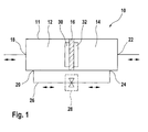
- Fig.1 shows a receiver dryer 10 comprising a housing 11 in which are arranged: a first drying chamber 12, a second drying chamber 14 and a partition wall 16 for separating the two drying chambers 12, 14.
- the receiver dryer 10 comprises a first circuit port 18 for leading refrigerant from a first heat exchanger (not shown) into the first drying chamber 12 and a first expansion device port 20 for leading the refrigerant out of the first drying chamber 12.
- the receiver dryer 10 comprises a second circuit port 22 for leading refrigerant from a second heat exchanger (not shown) into the second drying chamber 14 and a second expansion device port 24 for leading the refrigerant out of the second drying chamber 14.
- the first and second expansion device ports 20, 24 are connected to one another by means of a fluid line 26 comprising an expansion device 28 between the first and second expansion device ports 20, 24.
- the refrigerant always flows through one of the drying chambers 12, 14 then through the expansion device 28 and finally through the other of the drying chambers 12, 14.
- the partition wall 16 is arranged in the housing 11 in such a way that the size of the drying chambers 12, 14 can be increased and decreased respectively.
- One of the drying chambers 12, 14 can be increased in size at the expense of the other drying chamber12, 14. Indeed, while the drying chamber upstream of the expansion device 28 needs to be of certain size to allow storage of refrigerant, the drying chamber downstream of the expansion device 28 can be much smaller.
- the partition wall 16 can e.g. be a sliding piston, which moves such as to increase the size of one drying chamber, thereby decreasing the size of the other drying chamber.
- the operation of the moving partition wall can be controlled by means of the pressure difference in the two drying chambers 12, 14.
- the pressure in the drying chamber upstream of the expansion device is always higher than the pressure in the drying chamber downstream of the expansion device.
- the partition wall is therefore moved so as to increase the drying chamber upstream of the expansion device and decrease the size of the drying chamber downstream of the expansion device by the same amount.
- the receiver dryer according to the invention is of similar size to a conventional receiver dryer having only one drying chamber.
- Fig.2 shows the receiver dryer 10 of Fig.1 mounted in an air conditioning system 40 operating in cooling mode.
- the system 40 comprises a compressor 42, a four-way valve 44, a first heat exchanger 46, the receiver dryer 10, the expansion device 28 and a second heat exchanger 48.
- the different elements 42, 46, 10, 28, 48 are connected by fluid pipes and form a closed circuit wherein a refrigerant can circulate.
- the refrigerant exits the compressor 42 under high pressure for the four-way valve 44, which determines the direction of the refrigerant in the circuit.
- cooling mode i.e. when the inside compartment of a vehicle is to be cooled, the refrigerant exits the four-way valve 44 for the first heat exchanger 46, where it is condensed.
- the condensed refrigerant then enters the first drying chamber 12 of the receiver dryer 10 via the first circuit port 18.
- the pressure in the first drying chamber 12 is higher than the pressure in the second drying chamber 14.
- the partition wall 16 has therefore been displaced so as to increase the size of the first drying chamber 12 and decrease the size of the second drying chamber 14.
- the refrigerant collects in the first drying chamber 12 and moisture is removed from the refrigerant by means of the desiccant material 30 arranged in the first drying chamber 12.
- the refrigerant leaves the first drying chamber 12 via the first expansion device port 20 for the expansion device 28, where the refrigerant expands and drops in pressure.
- the refrigerant flows through the second drying chamber 14 of the receiver dryer 10 for the second heat exchanger 48 where it evaporates.
- the refrigerant then flows back to the four-way valve 44 and through sensing means 50 of the expansion device 28 where the temperature and pressure of the refrigerant are sensed. Sensing can be relayed to the expansion device electronically or by way of a sensing bulb.
- the refrigerant then finally flows back to the compressor 42.
- Fig.3 shows the receiver dryer 10 of Fig.1 mounted in the air conditioning system 40 operating in heating mode.
- the refrigerant In heating mode, i.e. when the inside compartment of a vehicle is to be heated, the refrigerant exits the four-way valve 44 for the second heat exchanger 48, where it is condensed.
- the condensed refrigerant then enters the second drying chamber 14 of the receiver dryer 10 via the second circuit port 22.
- the pressure in the second drying chamber 14 is higher than the pressure in the first drying chamber 12.
- the partition wall 16 has therefore been displaced so as to increase the size of the second drying chamber 14 and decrease the size of the first drying chamber 12.
- the refrigerant collects in the second drying chamber 14 and moisture is removed from the refrigerant by means of the desiccant material 32 arranged in the second drying chamber 14.
- the refrigerant leaves the second drying chamber 14 via the second expansion device port 24 for the expansion device 28, where the refrigerant expands and drops in pressure. From the expansion device 28, the refrigerant flows through the first drying chamber 12 of the receiver dryer 10 for the first heat exchanger 48 where it evaporates. The refrigerant then flows back to the four-way valve 44 and through sensing means 50 of the expansion device 28 where the temperature and pressure of the refrigerant are sensed. The refrigerant then finally flows back to the compressor 42.
- the expansion device 28 is preferably a thermal expansion valve of needle type.
- a thermal expansion valve comprises sensing means 50 for detecting the pressure and temperature of the refrigerant exiting the four-way valve 44 for the compressor 42. The detected pressure and temperature is used to regulate the thermal expansion valve.
- FIG. 4 A second embodiment of an air conditioning system is shown in Figs 4 and 5.
- the system 40' comprises a compressor 42, a four-way valve 44, a first heat exchanger 46, the receiver dryer 10, the expansion device 28, a second heat exchanger 48 and a third heat exchanger 52.
- the different elements 42, 46, 10, 28, 48, 52 are connected by fluid pipes and form a closed circuit wherein a refrigerant can circulate.
- the second and third heat exchangers 48, 52 are arranged in parallel between the receiver dryer 10 and the compressor 42.
- Valves 54, 56 are arranged in the circuit in order to direct the refrigerant either through the second or third heat exchanger 48, 52 depending on the mode of operation of the air conditioning system 40'.
- the air conditioning system 40' is shown operating in cooling mode.
- the refrigerant leaves the receiver dryer 10 via the second circuit port 22.
- a check valve 54 mounted upstream of the second heat exchanger 48 prevents the refrigerant from flowing into the second heat exchanger 48.
- a solenoid valve 56 is opened to allow the refrigerant to flow into the third heat exchanger 52 where it evaporates. From the third heat exchanger 52, the refrigerant flows back to the compressor 42 via the sensing means 50 of the expansion device 28.
- the second heat exchanger 48 is not used; no refrigerant flows through it.
- the air conditioning system 40' is shown operating in heating mode.
- the refrigerant leaves the compressor 42 and is directed by the four-way valve 44 into the second heat exchanger 48 where it condenses. From the second heat exchanger 48, the refrigerant flows through the check valve 54 to the receiver dryer 10.
- the solenoid valve 56 is now closed to prevent the refrigerant from flowing to the third heat exchanger 52.
- the third heat exchanger 52 is not used; no refrigerant flows through it.
- the second heat exchanger 48 always operates as condenser and the third heat exchanger 52 always operates as evaporator.
- the air conditioning system 40' allows to eliminate flash fogging.
- Figs 6 and 7 show preferred embodiments of the receiver dryer 10.
- the desiccant material 30, 32 is mounted on either side of the partition wall 16. Refrigerant entering the first drying chamber 12 through the first circuit port 18 is dried by means of the desiccant material 30.
- the refrigerant passes through a mesh filter 58 associated with the first expansion device port 20. Any debris in the refrigerant is thereby collected in the first drying chamber 12.
- the refrigerant then flows through the expansion device 28 towards the second expansion device port 24 and into the second drying chamber 14.
- the desiccant material 32 is arranged on the partition wall 16 in such a way that it covers the second circuit port 22.
- the refrigerant flowing through the second drying chamber 14 has to flow through the desiccant material 32 before leaving the second drying chamber 14.
- the desiccant material acts as filter and any debris contained in the second drying chamber 14 is prevented from flowing into the circuit via the second circuit port 22.
- a further mesh filter 60 is associated with the second expansion device port 24 to collect debris in the second drying chamber 14 when the flow of refrigerant is reversed. It will be understood that, when the flow of refrigerant is reversed, the desiccant material 30 covers the first circuit port 18.
- the desiccant material 30, 32 is not arranged on the partition wall 16, but is pivotably arranged so as to cover the first and second circuit ports 18, 22 respectively.
- the desiccant material 30, 32 is pivotably mounted at pivots 62, 64 so as to allow the desiccant material 30, 32 to uncover the first or second circuit port 18, 22 depending on the direction of flow of the refrigerant.
- the refrigerant flow forces the desiccant material 30 to uncover the first circuit port 18, so that the refrigerant can easily flow into the first drying chamber 12.
- the desiccant material 32 in the second drying chamber 14 is forced against the second circuit port 22 thereby covering the latter and preventing debris from leaving the second drying chamber 14 through the second circuit port 22.
- the desiccant material 32 uncovers the second circuit port 22 and the desiccant material 30 covers the first circuit port 18.
- FIGs 6 and 7 allow trapping debris in the first and second drying chambers 12, 14, thereby removing debris from the rest of the circuit.
Landscapes
- Engineering & Computer Science (AREA)
- Mechanical Engineering (AREA)
- General Engineering & Computer Science (AREA)
- Thermal Sciences (AREA)
- Physics & Mathematics (AREA)
- Power Engineering (AREA)
- Chemical & Material Sciences (AREA)
- Analytical Chemistry (AREA)
- Drying Of Solid Materials (AREA)
- Air-Conditioning For Vehicles (AREA)
- Amplifiers (AREA)
- Fixed Capacitors And Capacitor Manufacturing Machines (AREA)
- Telephonic Communication Services (AREA)
Abstract
Description
- The present invention generally relates to a bidirectional receiver dryer, in particular for use in a reversible air conditioning system.
- In a typical air conditioning system, a refrigerant in a vapor state is compressed by a compressor unit driven by a motor. The compressed refrigerant, at high temperature and pressure, enters a condenser where heat is removed from the compressed refrigerant and the refrigerant changes to a liquid state. The refrigerant then travels through a receiver dryer to an expansion device. The expansion device throttles the refrigerant as the refrigerant flows through an orifice, which causes the refrigerant to change phase from liquid to a saturated liquid/vapor mixture. The mixture then enters an evaporator, where heat is drawn from the environment, thus cooling the environmental air and causing the refrigerant to change to a vapor state. The low-pressure refrigerant flow from the evaporator returns to the suction side of the compressor to begin the cycle anew.
- Receiver dryer devices, in particular for use in automobile air conditioning units, are well known in the state of the art. They are generally located between the condenser and the expansion device and ensure that only liquid refrigerant is fed to the expansion device.
- In some automotive vehicles, e.g. in vehicles powered by traction motors supplied with electrical power from onboard fuel cells or batteries or in vehicles with advanced diesel engines, the internal combustion engine cannot be relied upon to provide the heat necessary for heating the passenger compartment of the vehicle in cold climate conditions. It has therefore been proposed to operate the air conditioning system as a heat pump, by reversing the flow of refrigerant. To operate the air conditioning system as a heat pump, a reversing valve can be provided and the flow is diverted such that the original evaporator becomes the condenser, the original condenser becomes the evaporator and the flow of refrigerant through the system is reversed. However, as the condenser can now also be located on the other side of the expansion device, a further receiver dryer device must be provided on the other side of the expansion device. This further receiver dryer unfortunately uses up valuable space and the whole system becomes heavier and more expensive.
- There was hence a need for a single receiver dryer that would be positioned between the condenser and the expansion device whether the system was used for cooling or for heating.
- Such a receiver dryer has been disclosed in US-5,832,741 to Hutchison at al. This receiver dryer comprises a drying chamber for removing moisture from the refrigerant and a bypass chamber for bypassing the drying chamber. The receiver dryer further comprises four ports, two circuit ports and two expansion device ports. The two circuit ports are connected to the evaporator and condenser respectively and the two expansion device ports are connected to the expansion device. Whatever mode the system is operated in, the refrigerant first flows via one of the circuit ports into the drying chamber of the receiver dryer, where it passes through the desiccant material and moisture is removed from the refrigerant. The refrigerant is then led via the first of the expansion device ports out of the receiver dryer and to the expansion device, where it expands. The refrigerant is then led from the expansion device into the bypass chamber of the receiver dryer via the second of the expansion device ports. The refrigerant finally leaves the receiver dryer via the other of the circuit ports. The flow of refrigerant within the receiver dryer is controlled by means of a rather complex arrangement of check valves. Four ball valves are arranged between the two circuit ports to direct the flow of refrigerant either through the drying chamber or through the bypass chamber. This complex arrangement of check valves makes the receiver dryer rather difficult to assemble and therefore also more expensive.
- The object of the present invention is to provide a bidirectional receiver dryer of simpler design.
- This object is achieved by a bidirectional receiver dryer according to
claim 1, wherein the receiver dryer comprises a housing, a first drying chamber and a second drying chamber within the housing, a partition wall arranged in the housing for separating the first and second drying chambers, and an expansion device fluidly connected between the first and second drying chambers. The partition wall is arranged so as to be able to increase the size of one of the drying chambers while at the same time decreasing the size of the other drying chamber, one of the drying chambers having its size increased at the expense of the other. - The receiver dryer according to the invention has one drying chamber arranged either side of the expansion device. Whichever mode the air conditioning system is operated in, the refrigerant always flows through one drying chamber, through the expansion device and then through the other drying chamber. There is therefore no need to provide the receiver dryer with any check valves to direct the flow of refrigerant through the receiver dryer. The present receiver dryer is therefore simpler in design and can be more cheaply produced. The absence of check valves also increases the reliability of the receiver dryer as there are fewer elements that can break down.
- Furthermore, due to the fact that the partition wall allows the drying chambers to be adapted in size and that one of the drying chambers has its size increased at the expense of the other, a more compact receiver dryer can be achieved. While the drying chamber upstream of the expansion device needs to have a certain size in order to be able to receive the refrigerant therein, the drying chamber downstream of the expansion device can be considerably smaller. Instead of arranging two drying chambers of certain size in the receiver dryer, the present invention proposes to provide a partition wall, which allows the drying chambers to vary in size. As the size of the drying chamber upstream of the expansion device is increased, the size of the other drying chamber is decreased by approximately the same amount.
- When the air conditioning system is operated in a first mode, a first of the drying chambers is increased in size so as to receive the refrigerant therein. At the same time, the second of the drying chambers is reduced in size and has no other function than allow the passage of the refrigerant. When the air conditioning system is operated in a second mode and the flow of refrigerant is reversed, the second of the drying chambers is increased in size so as to receive the refrigerant therein. At the same time, the first of the drying chambers is reduced in size and has no other function than allow the passage of the refrigerant. As only the drying chamber upstream of the expansion device is large, the overall size of the receiver dryer is reduced. In fact, the present bidirectional receiver dryer can be designed to be only marginally bigger than a conventional unidirectional receiver dryer with a single drying chamber. An air conditioning system comprising the present receiver dryer allows the operation in two different modes, i.e. heating and cooling, without the need for any check valves.
- It should also be noted that the drying chambers of the present receiver dryer are bidirectional, i.e. the refrigerant can flow through the drying chambers in either direction. This is in contrast to the drying chamber of US-5,832,741, which is unidirectional and where the refrigerant always flows from one of two inlet ports to an outlet port.
- Preferably, the partition wall is a sliding piston wherein stop elements are advantageously arranged in the first and second drying chambers so as to limit the movement of the sliding piston. Indeed, the ports of each drying chamber should remain open, and a passage should be maintained between the ports of each drying chamber so that refrigerant can flow through the drying chambers. The stop elements can also provide additional sealing between the drying chambers. The partition wall can however also be e.g. an elastic membrane.
- The partition wall is advantageously operated by means of the pressure difference between the two drying chambers. The pressure of the refrigerant in the drying chamber upstream of the expansion device is higher than the pressure of the refrigerant in the drying chamber downstream of the expansion device. Therefore, the partition wall can be moved, under influence of this pressure difference, so as to increase the size of the drying chamber upstream of the expansion device at the expense of the drying chamber downstream of the expansion device. There is therefore no need to provide separate drive or control means for the sliding piston and the receiver dryer is more reliable. The receiver dryer can also be produced more cheaply. It is however not excluded to operate the partition wall mechanically by providing drive or control means. Such control means can e.g. be useful if the pressure difference between the two drying chambers is not sufficient to move the partition wall.
- The receiver dryer preferably further comprises a first circuit port and a first expansion device port in connection with the first drying chamber; and a second circuit port and a second expansion device port in connection with the second drying chamber. The expansion device is then preferably arranged between the first expansion device port and the second expansion device port. This allows the expansion device to be arranged outside of the receiver dryer whereby it becomes more accessible for maintenance or replacement. It is however not excluded to provide an expansion device within the partition wall between the two drying chambers.
- The expansion device is preferably a thermal expansion valve. Advantageously, the thermal expansion valve is a needle valve, so that it is bidirectional. The expansion device can also be an electronic expansion valve.
- The receiver dryer is preferably ar ranged in an air conditioning system, wherein a refrigerant circulates in the system. The refrigerant used is e.g. R-12, R-134a, R-152 or CO2. Any other suitable refrigerant can however also be used.
- Desiccant material is preferably arranged in the drying chambers for removing moisture from the refrigerant. The desiccant material can e.g. be covering the circuit ports or the evaporation device ports, or it can be located on the partition wall.
- Advantageously, at least one filter, e.g. a mesh filter, is arranged in said drying chambers. Such a filter can e.g. be associated with the evaporation device ports, so as to prevent any debris from reaching the evaporation device and thereby damaging the latter. Filters can also be associated with the circuit ports, so as to prevent any debris from entering the receiver dryer. Preferably however, the debris is allowed to enter, but prevented from leaving, the receiver dryer. The debris in the system can thereby be trapped inside the drying chambers of the receiver dryer, rather than elsewhere in the system. In order to trap the debris inside the drying chambers, moveable filters are associated with the circuit ports. The moveable filters are arranged so as to cover, resp. uncover, the first, resp. second, circuit ports depending on the direction of flow of the refrigerant. Debris can thereby easily enter a drying chamber of the receiver dryer. When the flow of refrigerant is reversed, the debris in the drying chamber is prevented from leaving the drying chamber by means of the moveable filter which now covers the circuit port associated with that drying chamber. The desiccant material can e.g. act as moveable filter for preventing debris from leaving the drying chambers.
- The present invention also proposes an air conditioning system comprising a receiver dryer as described here above.
- The present invention will be more apparent from the following description of a not limiting embodiment with reference to the attached drawings, wherein
- Fig.1
- schematically illustrates a bidirectional receiver dryer according to the invention;
- Fig.2
- schematically illustrates a first embodiment an air conditioning system comprising the receiver dryer of Fig.1, wherein the air conditioning system operates in cooling mode;
- Fig.3
- schematically illustrates the air conditioning system of Fig.2 operating in heating mode;
- Fig.4
- schematically illustrates a second embodiment an air conditioning system comprising the receiver dryer of Fig.1, wherein the air conditioning system operates in cooling mode;
- Fig.5
- schematically illustrates the air conditioning system of Fig.4 operating in heating mode;
- Fig.6
- schematically illustrates a preferred embodiment of the receiver dryer of Fig.1; and
- Fig.7
- schematically illustrates another preferred embodiment of the receiver dryer of Fig. 1.
- Fig.1 shows a
receiver dryer 10 comprising ahousing 11 in which are arranged: afirst drying chamber 12, asecond drying chamber 14 and apartition wall 16 for separating the two dryingchambers receiver dryer 10 comprises afirst circuit port 18 for leading refrigerant from a first heat exchanger (not shown) into thefirst drying chamber 12 and a firstexpansion device port 20 for leading the refrigerant out of thefirst drying chamber 12. Thereceiver dryer 10 comprises asecond circuit port 22 for leading refrigerant from a second heat exchanger (not shown) into thesecond drying chamber 14 and a secondexpansion device port 24 for leading the refrigerant out of thesecond drying chamber 14. - The first and second
expansion device ports fluid line 26 comprising anexpansion device 28 between the first and secondexpansion device ports chambers expansion device 28 and finally through the other of the dryingchambers - The
partition wall 16 is arranged in thehousing 11 in such a way that the size of the dryingchambers chambers expansion device 28 needs to be of certain size to allow storage of refrigerant, the drying chamber downstream of theexpansion device 28 can be much smaller. By using such apartition wall 16, the sizes of the dryingchambers partition wall 16 can e.g. be a sliding piston, which moves such as to increase the size of one drying chamber, thereby decreasing the size of the other drying chamber. The operation of the moving partition wall can be controlled by means of the pressure difference in the two dryingchambers - Fig.2 shows the
receiver dryer 10 of Fig.1 mounted in anair conditioning system 40 operating in cooling mode. Thesystem 40 comprises acompressor 42, a four-way valve 44, afirst heat exchanger 46, thereceiver dryer 10, theexpansion device 28 and asecond heat exchanger 48. Thedifferent elements - The refrigerant exits the
compressor 42 under high pressure for the four-way valve 44, which determines the direction of the refrigerant in the circuit. In cooling mode, i.e. when the inside compartment of a vehicle is to be cooled, the refrigerant exits the four-way valve 44 for thefirst heat exchanger 46, where it is condensed. The condensed refrigerant then enters thefirst drying chamber 12 of thereceiver dryer 10 via thefirst circuit port 18. The pressure in thefirst drying chamber 12 is higher than the pressure in thesecond drying chamber 14. Thepartition wall 16 has therefore been displaced so as to increase the size of thefirst drying chamber 12 and decrease the size of thesecond drying chamber 14. The refrigerant collects in thefirst drying chamber 12 and moisture is removed from the refrigerant by means of thedesiccant material 30 arranged in thefirst drying chamber 12. The refrigerant leaves thefirst drying chamber 12 via the firstexpansion device port 20 for theexpansion device 28, where the refrigerant expands and drops in pressure. From theexpansion device 28, the refrigerant flows through thesecond drying chamber 14 of thereceiver dryer 10 for thesecond heat exchanger 48 where it evaporates. The refrigerant then flows back to the four-way valve 44 and through sensing means 50 of theexpansion device 28 where the temperature and pressure of the refrigerant are sensed. Sensing can be relayed to the expansion device electronically or by way of a sensing bulb. The refrigerant then finally flows back to thecompressor 42. - Fig.3 shows the
receiver dryer 10 of Fig.1 mounted in theair conditioning system 40 operating in heating mode. - In heating mode, i.e. when the inside compartment of a vehicle is to be heated, the refrigerant exits the four-
way valve 44 for thesecond heat exchanger 48, where it is condensed. The condensed refrigerant then enters thesecond drying chamber 14 of thereceiver dryer 10 via thesecond circuit port 22. The pressure in thesecond drying chamber 14 is higher than the pressure in thefirst drying chamber 12. Thepartition wall 16 has therefore been displaced so as to increase the size of thesecond drying chamber 14 and decrease the size of thefirst drying chamber 12. The refrigerant collects in thesecond drying chamber 14 and moisture is removed from the refrigerant by means of thedesiccant material 32 arranged in thesecond drying chamber 14. The refrigerant leaves thesecond drying chamber 14 via the secondexpansion device port 24 for theexpansion device 28, where the refrigerant expands and drops in pressure. From theexpansion device 28, the refrigerant flows through thefirst drying chamber 12 of thereceiver dryer 10 for thefirst heat exchanger 48 where it evaporates. The refrigerant then flows back to the four-way valve 44 and through sensing means 50 of theexpansion device 28 where the temperature and pressure of the refrigerant are sensed. The refrigerant then finally flows back to thecompressor 42. - It should further be noted that the
expansion device 28 is preferably a thermal expansion valve of needle type. Such a thermal expansion valve comprises sensing means 50 for detecting the pressure and temperature of the refrigerant exiting the four-way valve 44 for thecompressor 42. The detected pressure and temperature is used to regulate the thermal expansion valve. - A second embodiment of an air conditioning system is shown in Figs 4 and 5. The system 40' comprises a
compressor 42, a four-way valve 44, afirst heat exchanger 46, thereceiver dryer 10, theexpansion device 28, asecond heat exchanger 48 and athird heat exchanger 52. Thedifferent elements third heat exchangers receiver dryer 10 and thecompressor 42.Valves third heat exchanger - In Fig.4, the air conditioning system 40' is shown operating in cooling mode. The refrigerant leaves the
receiver dryer 10 via thesecond circuit port 22. Acheck valve 54 mounted upstream of thesecond heat exchanger 48 prevents the refrigerant from flowing into thesecond heat exchanger 48. Asolenoid valve 56 is opened to allow the refrigerant to flow into thethird heat exchanger 52 where it evaporates. From thethird heat exchanger 52, the refrigerant flows back to thecompressor 42 via the sensing means 50 of theexpansion device 28. When the system is operated in cooling mode, thesecond heat exchanger 48 is not used; no refrigerant flows through it. - In Fig.5, the air conditioning system 40' is shown operating in heating mode. The refrigerant leaves the
compressor 42 and is directed by the four-way valve 44 into thesecond heat exchanger 48 where it condenses. From thesecond heat exchanger 48, the refrigerant flows through thecheck valve 54 to thereceiver dryer 10. Thesolenoid valve 56 is now closed to prevent the refrigerant from flowing to thethird heat exchanger 52. When the system is operated in heating mode, thethird heat exchanger 52 is not used; no refrigerant flows through it. - In the air conditioning system 40', the
second heat exchanger 48 always operates as condenser and thethird heat exchanger 52 always operates as evaporator. The air conditioning system 40' allows to eliminate flash fogging. - Figs 6 and 7 show preferred embodiments of the
receiver dryer 10. In Fig.6, thedesiccant material partition wall 16. Refrigerant entering thefirst drying chamber 12 through thefirst circuit port 18 is dried by means of thedesiccant material 30. When leaving thefirst chamber 12 through the firstexpansion device port 20, the refrigerant passes through amesh filter 58 associated with the firstexpansion device port 20. Any debris in the refrigerant is thereby collected in thefirst drying chamber 12. The refrigerant then flows through theexpansion device 28 towards the secondexpansion device port 24 and into thesecond drying chamber 14. Thedesiccant material 32 is arranged on thepartition wall 16 in such a way that it covers thesecond circuit port 22. The refrigerant flowing through thesecond drying chamber 14 has to flow through thedesiccant material 32 before leaving thesecond drying chamber 14. The desiccant material acts as filter and any debris contained in thesecond drying chamber 14 is prevented from flowing into the circuit via thesecond circuit port 22. Afurther mesh filter 60 is associated with the secondexpansion device port 24 to collect debris in thesecond drying chamber 14 when the flow of refrigerant is reversed. It will be understood that, when the flow of refrigerant is reversed, thedesiccant material 30 covers thefirst circuit port 18. - In the embodiment of Fig.7, the
desiccant material partition wall 16, but is pivotably arranged so as to cover the first andsecond circuit ports desiccant material pivots desiccant material second circuit port desiccant material 30 to uncover thefirst circuit port 18, so that the refrigerant can easily flow into thefirst drying chamber 12. Thedesiccant material 32 in thesecond drying chamber 14 is forced against thesecond circuit port 22 thereby covering the latter and preventing debris from leaving thesecond drying chamber 14 through thesecond circuit port 22. When the flow of refrigerant is reversed, thedesiccant material 32 uncovers thesecond circuit port 22 and thedesiccant material 30 covers thefirst circuit port 18. - The embodiments shown in Figs 6 and 7 allow trapping debris in the first and
second drying chambers -
- 10
- receiver dryer
- 11
- housing
- 12
- first drying chamber
- 14
- second drying chamber
- 16
- partition wall
- 18
- first circuit port
- 20
- first expansion device port
- 22
- second circuit port
- 24
- second expansion device port
- 26
- fluid line
- 28
- expansion device
- 30
- desiccant material
- 32
- desiccant material
- 40
- air conditioning system
- 42
- compressor
- 44
- four-way valve
- 46
- first heat exchanger
- 48
- second heat exchanger
- 50
- sensing means
- 52
- third heat exchanger
- 54
- check valve
- 56
- solenoid valve
- 58
- mesh filter
- 60
- mesh filter
- 62
- pivot
- 64
- pivot
Claims (11)
- Bidirectional receiver dryer comprising:a housing;a first drying chamber and a second drying chamber within said housing;a partition wall arranged in said housing for separating said first and second drying chambers, said partition wall being arranged so as to be able to increase the size of one of the drying chambers while at the same time reducing the size of the other drying chamber, one of the drying chambers having its size increased at the expense of the other; andan expansion device fluidly connected between said first and second drying chambers.
- Receiver dryer according to claim 1, wherein said partition wall is a sliding piston.
- Receiver dryer according to claim 1, wherein said partition wall is an elastic membrane.
- Receiver dryer according to claim 2, wherein said receiver dryer comprises
a first stop element in said first drying chamber; and
a second stop element in said second drying chamber. - Receiver dryer according to any one of the previous claims, wherein the size of the drying chambers is determined by the pressure difference between the first and second drying chambers.
- Receiver dryer according to any one of the previous claims, further comprising:a first circuit port and a first expansion device port in connection with said first drying chamber; anda second circuit port and a second expansion device port in connection with said second drying chamber;said expansion device being arranged between said first expansion device port and said second expansion device port.
- Receiver dryer according to any one of the previous claims, wherein said expansion device is a thermal expansion valve or an electronic expansion valve.
- Receiver dryer according to any one of the previous claims, wherein said receiver dryer is arranged in an air conditioning system, wherein a refrigerant circulates in said system, the refrigerant being R152, R134a, R12, CO2.
- Receiver dryer according to any one of the previous claims, wherein desiccant material is arranged in said drying chambers.
- Receiver dryer according to any one of the previous claims, wherein a filter is arranged in said drying chambers.
- Air conditioning system comprising a receiver dryer according to any one of claims 1 to 10.
Applications Claiming Priority (2)
| Application Number | Priority Date | Filing Date | Title |
|---|---|---|---|
| LU90945 | 2002-08-05 | ||
| LU90945A LU90945B1 (en) | 2002-08-05 | 2002-08-05 | Bidirectional receiver dryer |
Publications (2)
| Publication Number | Publication Date |
|---|---|
| EP1388718A1 true EP1388718A1 (en) | 2004-02-11 |
| EP1388718B1 EP1388718B1 (en) | 2008-04-09 |
Family
ID=30439447
Family Applications (1)
| Application Number | Title | Priority Date | Filing Date |
|---|---|---|---|
| EP03102266A Expired - Lifetime EP1388718B1 (en) | 2002-08-05 | 2003-07-23 | Bidirectional receiver dryer |
Country Status (4)
| Country | Link |
|---|---|
| EP (1) | EP1388718B1 (en) |
| AT (1) | ATE391890T1 (en) |
| DE (1) | DE60320188T2 (en) |
| LU (1) | LU90945B1 (en) |
Cited By (1)
| Publication number | Priority date | Publication date | Assignee | Title |
|---|---|---|---|---|
| EP2165127A4 (en) * | 2007-05-16 | 2013-03-27 | Carrier Corp | Refrigerant accumulator |
Families Citing this family (1)
| Publication number | Priority date | Publication date | Assignee | Title |
|---|---|---|---|---|
| DE102014203578A1 (en) * | 2014-02-27 | 2015-08-27 | Siemens Aktiengesellschaft | Heat pump with storage tank |
Citations (6)
| Publication number | Priority date | Publication date | Assignee | Title |
|---|---|---|---|---|
| US2715317A (en) * | 1955-01-03 | 1955-08-16 | Robert L Rhodes | Automatic load control for a reversible heat pump and air conditioner |
| US4227901A (en) * | 1978-07-26 | 1980-10-14 | Sporlan Valve Company | Filter-drier for heat pump systems |
| US5749239A (en) * | 1995-11-20 | 1998-05-12 | Valeo Climatisation | Refrigerant fluid reservoir for a heat pump installation |
| EP0860309A2 (en) * | 1997-02-24 | 1998-08-26 | Zexel Corporation | Carbon dioxide gas refrigeration cycle |
| JPH10259963A (en) * | 1997-03-19 | 1998-09-29 | Mitsubishi Electric Corp | Refrigeration cycle device |
| US6082128A (en) * | 1998-11-12 | 2000-07-04 | Daimlerchrysler Corporation | Reversible air conditioning and heat pump HVAC system for electric vehicles |
Family Cites Families (1)
| Publication number | Priority date | Publication date | Assignee | Title |
|---|---|---|---|---|
| US5832741A (en) | 1996-10-18 | 1998-11-10 | Eaton Corporation | Filter/drier for reversible heat pump system |
-
2002
- 2002-08-05 LU LU90945A patent/LU90945B1/en active
-
2003
- 2003-07-23 EP EP03102266A patent/EP1388718B1/en not_active Expired - Lifetime
- 2003-07-23 AT AT03102266T patent/ATE391890T1/en not_active IP Right Cessation
- 2003-07-23 DE DE60320188T patent/DE60320188T2/en not_active Expired - Lifetime
Patent Citations (6)
| Publication number | Priority date | Publication date | Assignee | Title |
|---|---|---|---|---|
| US2715317A (en) * | 1955-01-03 | 1955-08-16 | Robert L Rhodes | Automatic load control for a reversible heat pump and air conditioner |
| US4227901A (en) * | 1978-07-26 | 1980-10-14 | Sporlan Valve Company | Filter-drier for heat pump systems |
| US5749239A (en) * | 1995-11-20 | 1998-05-12 | Valeo Climatisation | Refrigerant fluid reservoir for a heat pump installation |
| EP0860309A2 (en) * | 1997-02-24 | 1998-08-26 | Zexel Corporation | Carbon dioxide gas refrigeration cycle |
| JPH10259963A (en) * | 1997-03-19 | 1998-09-29 | Mitsubishi Electric Corp | Refrigeration cycle device |
| US6082128A (en) * | 1998-11-12 | 2000-07-04 | Daimlerchrysler Corporation | Reversible air conditioning and heat pump HVAC system for electric vehicles |
Non-Patent Citations (1)
| Title |
|---|
| PATENT ABSTRACTS OF JAPAN vol. 1998, no. 14 31 December 1998 (1998-12-31) * |
Cited By (1)
| Publication number | Priority date | Publication date | Assignee | Title |
|---|---|---|---|---|
| EP2165127A4 (en) * | 2007-05-16 | 2013-03-27 | Carrier Corp | Refrigerant accumulator |
Also Published As
| Publication number | Publication date |
|---|---|
| LU90945B1 (en) | 2004-02-06 |
| DE60320188T2 (en) | 2009-05-07 |
| ATE391890T1 (en) | 2008-04-15 |
| DE60320188D1 (en) | 2008-05-21 |
| EP1388718B1 (en) | 2008-04-09 |
Similar Documents
| Publication | Publication Date | Title |
|---|---|---|
| CN114341574B (en) | connection components | |
| CA2607789C (en) | Vehicle cabin heating cooling and ventilation system | |
| US7080520B2 (en) | Air conditioning system | |
| US9696070B2 (en) | Flow rate adjustment valve for refrigeration cycle | |
| US6971246B2 (en) | Vehicle air conditioner with front and rear air conditioning units | |
| US6237351B1 (en) | Heat pump type refrigerant cycle system | |
| EP2463131B1 (en) | Vehicle air conditioning system | |
| US6543531B1 (en) | Device and method for heating and cooling a compartment of a motor vehicle | |
| US4220197A (en) | High speed variable delivery helical screw compressor/expander automotive air conditioning and waste heat energy _recovery system | |
| US9562712B2 (en) | Vehicular air-conditioning unit | |
| US10451317B2 (en) | Refrigeration cycle device | |
| US20200398645A1 (en) | Vapor injection heat pump and control method | |
| CN116056922B (en) | Steam injection module and heat pump system using the steam injection module | |
| CN108603702A (en) | Heat pump cycle | |
| KR20190057770A (en) | Heat Pump For a Vehicle | |
| CN110065361A (en) | Heat pump system with multi-pass point valve | |
| EP1295739B1 (en) | Combined heating and cooling system | |
| EP2572910A1 (en) | Vehicle heating and cooling device | |
| EP1388718B1 (en) | Bidirectional receiver dryer | |
| CN115320324B (en) | Thermal management system | |
| JP3830242B2 (en) | Heat pump type automotive air conditioner | |
| WO2004005058A1 (en) | Hvac system with post-shut down isolation and venting of evaporator using h-shaped valve | |
| JP3825929B2 (en) | Refrigeration cycle with bypass | |
| JP4346781B2 (en) | Air conditioner for vehicles | |
| JP4039134B2 (en) | Valve device used in refrigeration cycle equipment |
Legal Events
| Date | Code | Title | Description |
|---|---|---|---|
| PUAI | Public reference made under article 153(3) epc to a published international application that has entered the european phase |
Free format text: ORIGINAL CODE: 0009012 |
|
| AK | Designated contracting states |
Kind code of ref document: A1 Designated state(s): AT BE BG CH CY CZ DE DK EE ES FI FR GB GR HU IE IT LI LU MC NL PT RO SE SI SK TR |
|
| AX | Request for extension of the european patent |
Extension state: AL LT LV MK |
|
| 17P | Request for examination filed |
Effective date: 20040506 |
|
| AKX | Designation fees paid |
Designated state(s): AT BE BG CH CY CZ DE DK EE ES FI FR GB GR HU IE IT LI LU MC NL PT RO SE SI SK TR |
|
| GRAP | Despatch of communication of intention to grant a patent |
Free format text: ORIGINAL CODE: EPIDOSNIGR1 |
|
| GRAS | Grant fee paid |
Free format text: ORIGINAL CODE: EPIDOSNIGR3 |
|
| GRAA | (expected) grant |
Free format text: ORIGINAL CODE: 0009210 |
|
| AK | Designated contracting states |
Kind code of ref document: B1 Designated state(s): AT BE BG CH CY CZ DE DK EE ES FI FR GB GR HU IE IT LI LU MC NL PT RO SE SI SK TR |
|
| REG | Reference to a national code |
Ref country code: GB Ref legal event code: FG4D |
|
| REG | Reference to a national code |
Ref country code: CH Ref legal event code: EP |
|
| REG | Reference to a national code |
Ref country code: IE Ref legal event code: FG4D |
|
| REF | Corresponds to: |
Ref document number: 60320188 Country of ref document: DE Date of ref document: 20080521 Kind code of ref document: P |
|
| PG25 | Lapsed in a contracting state [announced via postgrant information from national office to epo] |
Ref country code: SI Free format text: LAPSE BECAUSE OF FAILURE TO SUBMIT A TRANSLATION OF THE DESCRIPTION OR TO PAY THE FEE WITHIN THE PRESCRIBED TIME-LIMIT Effective date: 20080409 |
|
| NLV1 | Nl: lapsed or annulled due to failure to fulfill the requirements of art. 29p and 29m of the patents act | ||
| ET | Fr: translation filed | ||
| PG25 | Lapsed in a contracting state [announced via postgrant information from national office to epo] |
Ref country code: ES Free format text: LAPSE BECAUSE OF FAILURE TO SUBMIT A TRANSLATION OF THE DESCRIPTION OR TO PAY THE FEE WITHIN THE PRESCRIBED TIME-LIMIT Effective date: 20080720 Ref country code: FI Free format text: LAPSE BECAUSE OF FAILURE TO SUBMIT A TRANSLATION OF THE DESCRIPTION OR TO PAY THE FEE WITHIN THE PRESCRIBED TIME-LIMIT Effective date: 20080409 Ref country code: NL Free format text: LAPSE BECAUSE OF FAILURE TO SUBMIT A TRANSLATION OF THE DESCRIPTION OR TO PAY THE FEE WITHIN THE PRESCRIBED TIME-LIMIT Effective date: 20080409 Ref country code: BG Free format text: LAPSE BECAUSE OF FAILURE TO SUBMIT A TRANSLATION OF THE DESCRIPTION OR TO PAY THE FEE WITHIN THE PRESCRIBED TIME-LIMIT Effective date: 20080709 Ref country code: PT Free format text: LAPSE BECAUSE OF FAILURE TO SUBMIT A TRANSLATION OF THE DESCRIPTION OR TO PAY THE FEE WITHIN THE PRESCRIBED TIME-LIMIT Effective date: 20080909 |
|
| PG25 | Lapsed in a contracting state [announced via postgrant information from national office to epo] |
Ref country code: AT Free format text: LAPSE BECAUSE OF FAILURE TO SUBMIT A TRANSLATION OF THE DESCRIPTION OR TO PAY THE FEE WITHIN THE PRESCRIBED TIME-LIMIT Effective date: 20080409 |
|
| PG25 | Lapsed in a contracting state [announced via postgrant information from national office to epo] |
Ref country code: SE Free format text: LAPSE BECAUSE OF FAILURE TO SUBMIT A TRANSLATION OF THE DESCRIPTION OR TO PAY THE FEE WITHIN THE PRESCRIBED TIME-LIMIT Effective date: 20080709 Ref country code: DK Free format text: LAPSE BECAUSE OF FAILURE TO SUBMIT A TRANSLATION OF THE DESCRIPTION OR TO PAY THE FEE WITHIN THE PRESCRIBED TIME-LIMIT Effective date: 20080409 Ref country code: CZ Free format text: LAPSE BECAUSE OF FAILURE TO SUBMIT A TRANSLATION OF THE DESCRIPTION OR TO PAY THE FEE WITHIN THE PRESCRIBED TIME-LIMIT Effective date: 20080409 |
|
| PLBE | No opposition filed within time limit |
Free format text: ORIGINAL CODE: 0009261 |
|
| STAA | Information on the status of an ep patent application or granted ep patent |
Free format text: STATUS: NO OPPOSITION FILED WITHIN TIME LIMIT |
|
| PG25 | Lapsed in a contracting state [announced via postgrant information from national office to epo] |
Ref country code: SK Free format text: LAPSE BECAUSE OF FAILURE TO SUBMIT A TRANSLATION OF THE DESCRIPTION OR TO PAY THE FEE WITHIN THE PRESCRIBED TIME-LIMIT Effective date: 20080409 Ref country code: BE Free format text: LAPSE BECAUSE OF FAILURE TO SUBMIT A TRANSLATION OF THE DESCRIPTION OR TO PAY THE FEE WITHIN THE PRESCRIBED TIME-LIMIT Effective date: 20080409 Ref country code: RO Free format text: LAPSE BECAUSE OF FAILURE TO SUBMIT A TRANSLATION OF THE DESCRIPTION OR TO PAY THE FEE WITHIN THE PRESCRIBED TIME-LIMIT Effective date: 20080409 |
|
| REG | Reference to a national code |
Ref country code: CH Ref legal event code: PL |
|
| 26N | No opposition filed |
Effective date: 20090112 |
|
| GBPC | Gb: european patent ceased through non-payment of renewal fee |
Effective date: 20080723 |
|
| PG25 | Lapsed in a contracting state [announced via postgrant information from national office to epo] |
Ref country code: MC Free format text: LAPSE BECAUSE OF NON-PAYMENT OF DUE FEES Effective date: 20080731 |
|
| PG25 | Lapsed in a contracting state [announced via postgrant information from national office to epo] |
Ref country code: EE Free format text: LAPSE BECAUSE OF FAILURE TO SUBMIT A TRANSLATION OF THE DESCRIPTION OR TO PAY THE FEE WITHIN THE PRESCRIBED TIME-LIMIT Effective date: 20080409 |
|
| PG25 | Lapsed in a contracting state [announced via postgrant information from national office to epo] |
Ref country code: CH Free format text: LAPSE BECAUSE OF NON-PAYMENT OF DUE FEES Effective date: 20080731 Ref country code: GB Free format text: LAPSE BECAUSE OF NON-PAYMENT OF DUE FEES Effective date: 20080723 Ref country code: LI Free format text: LAPSE BECAUSE OF NON-PAYMENT OF DUE FEES Effective date: 20080731 |
|
| PG25 | Lapsed in a contracting state [announced via postgrant information from national office to epo] |
Ref country code: IE Free format text: LAPSE BECAUSE OF NON-PAYMENT OF DUE FEES Effective date: 20080723 |
|
| PG25 | Lapsed in a contracting state [announced via postgrant information from national office to epo] |
Ref country code: CY Free format text: LAPSE BECAUSE OF FAILURE TO SUBMIT A TRANSLATION OF THE DESCRIPTION OR TO PAY THE FEE WITHIN THE PRESCRIBED TIME-LIMIT Effective date: 20080409 |
|
| PG25 | Lapsed in a contracting state [announced via postgrant information from national office to epo] |
Ref country code: HU Free format text: LAPSE BECAUSE OF FAILURE TO SUBMIT A TRANSLATION OF THE DESCRIPTION OR TO PAY THE FEE WITHIN THE PRESCRIBED TIME-LIMIT Effective date: 20081010 Ref country code: LU Free format text: LAPSE BECAUSE OF NON-PAYMENT OF DUE FEES Effective date: 20080723 |
|
| PG25 | Lapsed in a contracting state [announced via postgrant information from national office to epo] |
Ref country code: TR Free format text: LAPSE BECAUSE OF FAILURE TO SUBMIT A TRANSLATION OF THE DESCRIPTION OR TO PAY THE FEE WITHIN THE PRESCRIBED TIME-LIMIT Effective date: 20080409 |
|
| PG25 | Lapsed in a contracting state [announced via postgrant information from national office to epo] |
Ref country code: GR Free format text: LAPSE BECAUSE OF FAILURE TO SUBMIT A TRANSLATION OF THE DESCRIPTION OR TO PAY THE FEE WITHIN THE PRESCRIBED TIME-LIMIT Effective date: 20080710 |
|
| REG | Reference to a national code |
Ref country code: DE Ref legal event code: R082 Ref document number: 60320188 Country of ref document: DE Representative=s name: BRP RENAUD UND PARTNER MBB, DE Ref country code: DE Ref legal event code: R081 Ref document number: 60320188 Country of ref document: DE Owner name: MAHLE INTERNATIONAL GMBH, DE Free format text: FORMER OWNER: DELPHI TECHNOLOGIES, INC., TROY, MICH., US Ref country code: DE Ref legal event code: R082 Ref document number: 60320188 Country of ref document: DE Representative=s name: BRP RENAUD UND PARTNER MBB RECHTSANWAELTE PATE, DE |
|
| REG | Reference to a national code |
Ref country code: FR Ref legal event code: PLFP Year of fee payment: 14 |
|
| REG | Reference to a national code |
Ref country code: FR Ref legal event code: PLFP Year of fee payment: 15 |
|
| REG | Reference to a national code |
Ref country code: FR Ref legal event code: TP Owner name: MAHLE INTERNATIONAL GMBH, DE Effective date: 20180103 |
|
| REG | Reference to a national code |
Ref country code: FR Ref legal event code: PLFP Year of fee payment: 16 |
|
| PGFP | Annual fee paid to national office [announced via postgrant information from national office to epo] |
Ref country code: IT Payment date: 20180725 Year of fee payment: 16 Ref country code: FR Payment date: 20180726 Year of fee payment: 16 |
|
| PGFP | Annual fee paid to national office [announced via postgrant information from national office to epo] |
Ref country code: DE Payment date: 20180928 Year of fee payment: 16 |
|
| REG | Reference to a national code |
Ref country code: DE Ref legal event code: R119 Ref document number: 60320188 Country of ref document: DE |
|
| PG25 | Lapsed in a contracting state [announced via postgrant information from national office to epo] |
Ref country code: DE Free format text: LAPSE BECAUSE OF NON-PAYMENT OF DUE FEES Effective date: 20200201 |
|
| PG25 | Lapsed in a contracting state [announced via postgrant information from national office to epo] |
Ref country code: FR Free format text: LAPSE BECAUSE OF NON-PAYMENT OF DUE FEES Effective date: 20190731 |
|
| PG25 | Lapsed in a contracting state [announced via postgrant information from national office to epo] |
Ref country code: IT Free format text: LAPSE BECAUSE OF NON-PAYMENT OF DUE FEES Effective date: 20190723 |