EP1388636A1 - Transmission mechanism for a motor-driven blind - Google Patents
Transmission mechanism for a motor-driven blind Download PDFInfo
- Publication number
- EP1388636A1 EP1388636A1 EP02255528A EP02255528A EP1388636A1 EP 1388636 A1 EP1388636 A1 EP 1388636A1 EP 02255528 A EP02255528 A EP 02255528A EP 02255528 A EP02255528 A EP 02255528A EP 1388636 A1 EP1388636 A1 EP 1388636A1
- Authority
- EP
- European Patent Office
- Prior art keywords
- modulation wheel
- wheel
- amplitude modulation
- frequency modulation
- transmission mechanism
- Prior art date
- Legal status (The legal status is an assumption and is not a legal conclusion. Google has not performed a legal analysis and makes no representation as to the accuracy of the status listed.)
- Withdrawn
Links
- 230000005540 biological transmission Effects 0.000 title claims abstract description 67
- 230000007246 mechanism Effects 0.000 title claims abstract description 54
- 230000001360 synchronised effect Effects 0.000 claims abstract description 11
- 230000033001 locomotion Effects 0.000 claims description 12
- 230000002093 peripheral effect Effects 0.000 claims description 12
- 230000008878 coupling Effects 0.000 claims description 6
- 238000010168 coupling process Methods 0.000 claims description 6
- 238000005859 coupling reaction Methods 0.000 claims description 6
- 238000005096 rolling process Methods 0.000 claims description 4
- 238000004891 communication Methods 0.000 claims description 2
- 238000006073 displacement reaction Methods 0.000 claims 1
- 230000000694 effects Effects 0.000 claims 1
- 230000009471 action Effects 0.000 description 7
- 238000009434 installation Methods 0.000 description 3
- 230000002441 reversible effect Effects 0.000 description 2
- 230000008859 change Effects 0.000 description 1
- 230000001605 fetal effect Effects 0.000 description 1
- 238000004519 manufacturing process Methods 0.000 description 1
- QSHDDOUJBYECFT-UHFFFAOYSA-N mercury Chemical compound [Hg] QSHDDOUJBYECFT-UHFFFAOYSA-N 0.000 description 1
- 229910052753 mercury Inorganic materials 0.000 description 1
- 238000004804 winding Methods 0.000 description 1
Images






Classifications
-
- E—FIXED CONSTRUCTIONS
- E06—DOORS, WINDOWS, SHUTTERS, OR ROLLER BLINDS IN GENERAL; LADDERS
- E06B—FIXED OR MOVABLE CLOSURES FOR OPENINGS IN BUILDINGS, VEHICLES, FENCES OR LIKE ENCLOSURES IN GENERAL, e.g. DOORS, WINDOWS, BLINDS, GATES
- E06B9/00—Screening or protective devices for wall or similar openings, with or without operating or securing mechanisms; Closures of similar construction
- E06B9/24—Screens or other constructions affording protection against light, especially against sunshine; Similar screens for privacy or appearance; Slat blinds
- E06B9/26—Lamellar or like blinds, e.g. venetian blinds
- E06B9/28—Lamellar or like blinds, e.g. venetian blinds with horizontal lamellae, e.g. non-liftable
- E06B9/30—Lamellar or like blinds, e.g. venetian blinds with horizontal lamellae, e.g. non-liftable liftable
- E06B9/32—Operating, guiding, or securing devices therefor
- E06B9/322—Details of operating devices, e.g. pulleys, brakes, spring drums, drives
-
- E—FIXED CONSTRUCTIONS
- E06—DOORS, WINDOWS, SHUTTERS, OR ROLLER BLINDS IN GENERAL; LADDERS
- E06B—FIXED OR MOVABLE CLOSURES FOR OPENINGS IN BUILDINGS, VEHICLES, FENCES OR LIKE ENCLOSURES IN GENERAL, e.g. DOORS, WINDOWS, BLINDS, GATES
- E06B9/00—Screening or protective devices for wall or similar openings, with or without operating or securing mechanisms; Closures of similar construction
- E06B9/24—Screens or other constructions affording protection against light, especially against sunshine; Similar screens for privacy or appearance; Slat blinds
- E06B9/26—Lamellar or like blinds, e.g. venetian blinds
- E06B9/28—Lamellar or like blinds, e.g. venetian blinds with horizontal lamellae, e.g. non-liftable
- E06B9/30—Lamellar or like blinds, e.g. venetian blinds with horizontal lamellae, e.g. non-liftable liftable
- E06B9/32—Operating, guiding, or securing devices therefor
- E06B9/322—Details of operating devices, e.g. pulleys, brakes, spring drums, drives
- E06B2009/3225—Arrangements to aid the winding of cords rollers
- E06B2009/3227—Axially moving rollers
-
- E—FIXED CONSTRUCTIONS
- E06—DOORS, WINDOWS, SHUTTERS, OR ROLLER BLINDS IN GENERAL; LADDERS
- E06B—FIXED OR MOVABLE CLOSURES FOR OPENINGS IN BUILDINGS, VEHICLES, FENCES OR LIKE ENCLOSURES IN GENERAL, e.g. DOORS, WINDOWS, BLINDS, GATES
- E06B9/00—Screening or protective devices for wall or similar openings, with or without operating or securing mechanisms; Closures of similar construction
- E06B9/56—Operating, guiding or securing devices or arrangements for roll-type closures; Spring drums; Tape drums; Counterweighting arrangements therefor
- E06B9/68—Operating devices or mechanisms, e.g. with electric drive
- E06B2009/6809—Control
- E06B2009/6872—Control using counters to determine shutter position
- E06B2009/6881—Mechanical counters
Definitions
- the present invention relates to Venetian blinds and, more specifically, to a transmission mechanism for a motor-driven blind.
- a regular Venetian blind comprises a headrail, a bottom rail, a plurality of slats arranged in parallel between the headrail and the bottom rail, an amplitude modulation control mechanism for controlling lifting and positioning of the bottom rail to change the extending area of the blind, a frequency modulation control mechanism for controlling the tilting angle of the slats to regulate the light.
- the amplitude modulation control mechanism comprises an endless lift cord suspended from the headrail at one lateral side for pulling by hand to lift/lower the bottom rail.
- the frequency modulation control mechanism comprises a frequency modulation member disposed at one lateral side of the blind for permitting rotation by the user to regulate the tilting angle of the slats.
- US Patent No. 5103888 discloses a motor-driven blind, which keeps the lift cord from sight.
- a motor is mounted in the headrail or bottom rail, and controlled by a remote controller to roll up or let off the lift cord.
- the motor is used to control lifting of the lift cord only.
- the user When adjusting the tilting angle of the slats, the user must approach the blind and touch-control a tilting control unit. This operation manner is still not convenient.
- the present invention has been accomplished to provide a transmission mechanism for a motor-driven blind, which eliminates the aforesaid drawbacks. It is the main object of the present invention to provide a transmission mechanism for a motor-driven blind, which controls lifting/lowering of the slats and bottom rail of the Venetian blind as well as tilting of the slats.
- the transmission mechanism is mounted in a motor-driven Venetian blind and adapted to be driven by a driving unit for controlling lifting/lowering of slats of said Venetian blind and tilting of said slats.
- the transmission mechanism comprises at least one cord roll-up unit having an amplitude modulation set, a frequency modulation set and a clutch.
- the amplitude modulation set has an amplitude modulation wheel coupled to said driving unit, and an amplitude modulation lift cord coupled to said amplitude modulation wheel and said slats and adapted to lift/lower said slats of said Venetian blind while the amplitude modulation wheel is driven by the driving unit to rotate.
- the frequency modulation set has a frequency modulation wheel being capable of synchronous rotation with said amplitude modulation wheel through said clutch, and a lift cord coupled to said frequency modulation wheel and said slats and adapted to tilt said slats of said Venetian blind through the rotation of the frequency modulation wheel driven by the amplitude modulation wheel.
- the clutch is capable of releasing the synchronous rotation between the frequency modulation wheel and the amplitude modulation wheel while the clutch is performed to a predetermined position.
- a first preferred embodiment of the present invention provides a transmission mechanism 100 mountable to a Venetian blind 10 including a driving unit 20 .
- the Venetian blind 10 as shown in FIG. 1, comprises a headrail 11 and a slat set 12.
- the headrail 11 is mountable to the top side of the window, comprising an inside holding chamber 111, and two through holes 112 bilaterally disposed at a bottom side in communication with the holding chamber 111 .
- the slat set 12 is comprised of a plurality of slats 121 and a bottom rail 123. Each slat 121 has two-wire holes 122 corresponding to the through holes 112 of the headrail 11. Because the Venetian blind 10 is of the known art, no further detailed structural description is necessary.
- the driving unit 20 comprises a reversible motor 21, a transmission shaft 22, a signal transmitter 23, a signal receiver 24, and a battery 25.
- the motor 21 is mounted inside the holding chamber 111 of the headrail 11.
- the transmission shaft 22 is a rod member of non-circular cross section, having one end coupled to the motor 21 for rotation by the motor 21.
- the signal transmitter 23 can be a remote controller or wired controller for providing control signal to the signal receiver 24. According to the present preferred embodiment, the signal transmitter 23 is a wireless remote controller.
- the signal receiver 24 is electrically connected to the motor 21, and adapted to control the operation of the motor 21 subject to the nature of the control signal received from the signal transmitter 23.
- the battery 25 can be a storage battery, dry battery, planar battery, cylindrical battery, or mercury battery mounted inside the holding chamber 111 and electrically connected to the motor 21 to provide the motor 21 with the necessary working power.
- the transmission mechanism 100 comprises two cord roll-up units 30 .
- the cord roll-up units 30 are respectively mounted inside the holding chamber 111 of the headrail 11 corresponding to the through holes 112, each comprised of an amplitude modulation set 31 , a frequency modulation set 32, and a clutch 33.
- the amplitude modulation set 31 comprises an amplitude modulation wheel 311, and an amplitude modulation lift cord 312.
- the amplitude modulation wheel 311 is a stepped cylindrical wheel, comprising a head 311b at one end, a tail 311e at an opposite end, a body 311c axially connected between the head 311b and the tail 311e, a cone 311d axially connected between the body 311c and the tail 311e and disposed corresponding to one through hole 112 of the headrail 11, a center through hole 311a of non-circular cross section axially extended through the tail 311e, the cone 311d , the body 311c and the head 311b and coupled to the transmission shaft 22 for enabling the amplitude modulation wheel 311 to be rotated with the transmission shaft 22, and a groove 311f longitudinally extended in the periphery of the head 311b toward the body 311c.
- the amplitude modulation lift cord 312 has one end fixedly connected to a fixed point 311g of the amplitude modulation wheel 311, and the other end inserted through one through hole 112 of the headrail 11 and one wire hole 122 of each slat 12 and then fixedly connected to the bottom rail 123.
- the frequency modulation set 32 is comprised of a frequency modulation wheel 321, and a frequency modulation lift cord 322.
- the frequency modulation wheel 321 comprises an axially extended circular hole 321d, a body 321a , and a head 321b.
- the body 321a is provided with a notch 321c .
- the outer diameter of the head 321b is greater than the outer diameter of the body 321a.
- the clutch 33 is comprised of a support 331, a spring 332, a stop block 333 , a link 334, and a limiter 335 .
- the support 331 is fixedly mounted inside the holding chamber 111 of the headrail 11, having a stepped center through hole formed of a through hole 331a and a recessed hole 331b.
- the inner diameter of the through hole 331a is smaller than the recessed hole 331b and the outer diameter of the amplitude modulation wheel 311 of the amplitude modulation set 31.
- the inner diameter of the recessed hole 311b is approximately equal to or slightly greater than the outer diameter of the head 311b of the amplitude modulation wheel 311, such that the head 311b of the amplitude modulation wheel 311 can be inserted into the recessed hole 311b to confine the position of the amplitude modulation wheel 311.
- the spring 332 is mounted in the groove 311f of the amplitude modulation wheel 311 , having one end stopped at one end of the groove 311f.
- the stop block 333 is fixedly fastened to the support 331 outside the recessed hole 331b, having a semicircular notch 333a, and two beveled faces 333b, 333c disposed at two sides of the semicircular notch 333a and respectively downwardly sloping from the top toward the recessed hole 331b.
- the link 334 is an oblong key member, having one end inserted into the groove 311f of the amplitude modulation wheel 311 and stopped against the spring 332 and the other end inserted into the notch 321c of the frequency modulation wheel 321. Therefore, the link 334 couples the frequency modulation wheel 321 to the amplitude modulation wheel 311 .
- the limiter 335 is fixedly fastened to the support 331, stopping the frequency modulation wheel 321 from falling out of the amplitude modulation wheel 311.
- the operation of the present invention is outlined hereinafter with reference to FIGS. from 5 through 13.
- the signal receiver 24 When the user operated the signal transmitter 23 of the driving unit 20 to transmit a control signal of lifting the Venetian blind, the signal receiver 24 immediately receives the control signal. Upon receipt of the control signal, the signal receiver 24 drives the motor 21 to rotate the transmission shaft 22. Because the center through hole 311a of the amplitude modulation wheel 311 is a non-circular hole that fits the transmission shaft 22 , rotating the transmission shaft 22 causes the amplitude modulation wheel 311 to be synchronously rotated to roll up the amplitude modulation lift cord 312 .
- the amplitude modulation wheel 311 moves axially in the support 331, keeping the amplitude modulation lift cord 312 to be smoothly wound round the periphery of the amplitude modulation wheel 311 from the conical surface of the cone 311d toward the tail 311e (see FIGS. 5 and 6).
- the amplitude modulation wheel b rolling up the amplitude modulation lift cord 312 the bottom rail 123 is lifted, thereby causing the slats 121 to be received and moved with the bottom rail 123 upwards toward the headrail 11 to the desired elevation.
- the frequency modulation wheel 321 is rotated with the amplitude modulation wheel 311 (see FIGS. 7 and 11).
- the frequency modulation lift cord 322 is moved, causing the slats 121 to be tilted.
- the frequency modulation wheel 321 turned to a predetermined position (the position where the link 334 touches the beveled face 333b of the stop block 333 (see FIGS. 8and 12), the link 334 moves along the beveled face 333b toward the recessed hole 331b (see FIG.
- the signal transmitter 23 When releasing the slats 121, operates the signal transmitter 23 to transmit a control signal of releasing the slats to the signal receiver 24.
- the signal receiver 24 Upon receipt of the signal, the signal receiver 24 immediately drives the motor 21 to rotate in the reversed direction, thereby causing the transmission shaft 22 and the amplitude modulation wheel 311 to be rotated in the same direction. Reverse rotation of the amplitude modulation wheel 311 lets off the amplitude modulation lift cord 312, and therefore the bottom rail 123 and the slats 121 are lowered to extend out the Venetian blind 10.
- the beveled face 333b of the stop block 333 keeps the frequency modulation wheel 321 out of the amplitude modulation wheel 311.
- the spring power of the spring 332 forces the link 334 into the notch 321c, thereby causing the frequency modulation wheel 321 and the amplitude modulation wheel 311 to be linked again.
- the frequency modulation wheel 321 is rotated with the amplitude modulation wheel 311 to tilt the bottom rail 123 and the slats 121 .
- the beveled face 333c forces the link 334 away from the frequency modulation wheel 321 to disconnect the amplitude modulation wheel 311 from the frequency modulation wheel 321.
- the transmission shaft 22 continuously rotates the amplitude modulation wheel 311 to let off the amplitude modulation lift cord 312 and to release the slats 121 without changing the tilting angle of the slats 121.
- the operation is described hereinafter.
- the user operates the signal transmitter 23 to transmit a slat tilting control signal to the signal receiver 24.
- the signal receiver 24 Upon receipt of the control signal, the signal receiver 24 immediately drives the motor 21 to rotate the transmission shaft 22 and the amplitude modulation wheel 311, and to further forces the link 334 into engagement with the amplitude modulation wheel 311 and the frequency modulation wheel 321 , permitting synchronous rotation of the frequency modulation wheel 321 with the amplitude modulation wheel 311 to let off the frequency modulation lift cord 322 and to further control the tilting angle of the slats 121 .
- the angle of rotation of the frequency modulation wheel 311 can be limited to a limited range.
- the frequency modulation wheel 321 is rotatable with the amplitude modulation wheel 311 within about 180°.
- the stop block 333 limits the angle of rotation of the frequency modulation wheel 311.
- the transmission mechanism 100 further comprises a sensor 40 installed in the middle of the transmission shaft 22.
- the sensor 40 When the slats 121 moved to the upper limit or lower limit position, the sensor 40 is induced to stop the motor 21.
- the sensor 40 comprises a mounting plate 41, a locating block 42, a wheel 43 , and two limit switches 44, 45.
- the mounting plate 41 is fixedly fastened to the peripheral wall of the holding chamber 111 of the headrail 11.
- the locating block 42 is fixedly mounted inside the holding chamber 111 of the headrail 11. having a center screw hole 421.
- the wheel 43 is coupled to the transmission shaft 22 for synchronous rotation, having an outer thread 431 threaded into the center screw hole 421 of the locating block 42. Rotation of the transmission shaft 22 causes synchronous rotation of the wheel 43 with the transmission shaft 22 and axial movement of the wheel 43 in the locating block 42.
- the limit switches 44, 45 are respectively mounted on the mounting plate 41 at two sides relative to the wheel 43 (at the ends of path for axial movement of the wheel 42 of the sensor 40 corresponding to the upper limit position and lower limit position of the slats 121 of the Venetian blind 10 ), and electrically connected to the motor 21. When the slats 121 moved to the upper or lower limit position, the wheel 43 touches one limit switch 44 or 45 , thereby causing the limit switch 44 or 45 to cut off power supply from the motor 21.
- FIGS. 18 ⁇ 22 show a transmission mechanism 200 used in a Venetian blind 10 having a driving unit 20 and a sensor 40 according to a second embodiment of the present invention.
- the transmission mechanism 200 comprises two cord roll-up units 50.
- Each cord roll-up unit 50 is comprised of an amplitude modulation set 51, a frequency modulation set 52, and a clutch 53.
- This embodiment is substantially similar to the aforesaid first embodiment of the present invention with the exception of the cord roll-up units 50 .
- the main features of this second embodiment are outlined hereinafter with reference to FIGS. from 19 through 22.
- the amplitude modulation wheel 511 of the amplitude modulation set 51 comprises an outer thread 511a extended around the periphery, and a longitudinal groove 511b extended in the periphery and cut through the outer thread 511a .
- the frequency modulation wheel 521 of the frequency modulation set 52 comprises a body 5 21a having a peripheral notch 521b.
- the clutch 53 is comprised of a support 531, a spring 532, a pressure ring 533, a stop block 534 , a link 535, and a limiter 536.
- the support 531 is fixedly mounted inside the holding chamber 111 of the headrail 11, having a stepped center through hole formed of a through hole 531a and a recessed hole 531b.
- the through hole 531a has a threaded section 531c threaded onto the outer thread 511a of the amplitude modulation wheel 511 of the amplitude modulation set 51.
- the spring 532 is sleeved onto the amplitude modulation wheel 511 and supported in between the through hole 531a and the recessed hole 531b .
- the pressure ring 533 is sleeved onto the amplitude modulation wheel 511 and stopped at the spring 532 against the support 531.
- the stop block 534 is fixedly fastened to the support 531 outside the recessed hole 531b and stopped at the pressure ring 533 against the spring 532, having a semicircular notch 534a and two beveled faces 534b, 534c disposed at two sides of the semicircular notch 534a and respectively downwardly sloping from the top toward the recessed hole 531b.
- the link 535 is an angled key member, having one end inserted into the longitudinal groove 511b of the amplitude modulation wheel 511 and stopped against the pressure ring 533 and the spring 532 and the other end inserted into the peripheral notch 521b of the frequency modulation wheel 521 . Therefore, the link 535 couples the frequency modulation wheel 521 to the amplitude modulation wheel 511 .
- the limiter 536 is fixedly fastened to the support 531, stopping the frequency modulation wheel 521 from falling out of the amplitude modulation wheel 511 .
- the link 535 couples the frequency modulation wheel 521 to the amplitude modulation wheel 511 for synchronous rotation. Further, by means of the relative action between the link 535 and the beveled faces 534b, 534c, the amplitude modulation wheel 511 is disconnected from the frequency modulation wheel 521. Therefore, one single driving source is sufficient to achieve amplitude modulation control and frequency modulation control. Further, because the amplitude modulation wheel 511 is coupled to the support 531 by a screw joint, the amplitude modulation wheel 511 is moved axially when rotated, keeping the amplitude modulation lift cord 512 smoothly wound round the periphery of the amplitude modulation wheel 511 (see FIG. 22).
- FIGS. 23 ⁇ 29 show a transmission mechanism 300 used in a Venetian blind 10 having a driving unit 20 and a sensor 40 according to a third embodiment of the present invention.
- the transmission mechanism 300 comprises two cord roll-up units 60.
- Each cord roll-up unit 60 is comprised of an amplitude modulation set 61, a frequency modulation set 62 , and a clutch 63 .
- the amplitude modulation set 61 is comprised of an amplitude modulation wheel 611 and an amplitude modulation lift cord 612.
- the main features of this third embodiment are outlined hereinafter with reference to FIGS. from 24 through 26.
- the amplitude modulation wheel 611 of the amplitude modulation set 61 is formed of a cylindrical wheel body 613, a bobbin 614 , and a stop key 615 .
- the wheel body 613 comprises a coupling portion 613b, a bearing portion 613d axially connected to the coupling portion 613b in a line, a collar 613c extended around the periphery of the connection area between the coupling portion 613b and the bearing portion 613d, a center through hole 613a of non-circular cross-section axially extended through the front and rear ends thereof and coupled to the transmission shaft 22 of the driving unit 20 for enabling the wheel body 613 to be synchronously rotated with the transmission shaft 22, and a recessed hole 613e disposed in the periphery of the bearing portion 613d adjacent the collar 613c .
- the stop key 615 is mounted in the recessed hole 613e and partially protruding over the outside wall of the bearing portion 613d.
- the bobbin 614 comprises a first inner hole 614a and a second inner hole 614b respectively axially extended from the two distal ends thereof toward each other, a protruded block 614c suspended in the second inner hole 614b, and a conical face 614d extended around the periphery at one end.
- the diameter of the first inner hole 614a is approximately equal to the outer diameter of the bearing portion 613d of the wheel body 613.
- the diameter of the second inner hole 614b is greater than the outer diameter of the bearing portion 613d of the wheel body 613.
- the bearing portion 613d of the wheel body 613 is inserted through the second inner hole 614b into the first inner hole 614a.
- the periphery of the bearing portion 613d is equally spaced from the peripheral wall of the second inner hole 614b of the bobbin 614, and the protruded block 614c is suspended in the second inner hole 614b around and without touching the periphery of the bearing portion 613d.
- the stop key 615 will be forced into contact with the protruded block 614c.
- the amplitude modulation lift cord 612 has one end fixedly fastened to the bobbin 614.
- the conical face 614d guides the winding of the amplitude modulation lift cord 612 round the periphery of the bobbin 614 smoothly.
- the frequency modulation set 62 is comprised of a frequency modulation wheel 621 and a frequency modulation lift cord 622 .
- the frequency modulation wheel 621 has a center through hole 621b coupled to the coupling portion 613b of the cylindrical wheel body 613 of the amplitude modulation wheel 611 , and a protrusion 621a protruded from one side thereof.
- the clutch 63 is comprised of a support 631, a spring 632, and a limiter 633 .
- the support 631 is fixedly mounted inside the holding chamber 111 of the headrail 11, having a stepped center through hole formed of a through hole 631a and a recessed hole 631b and two shoulders 631c, 631d bilaterally disposed in one sidewall thereof outside the recessed hole 631b and adapted to act with the protrusion 621a of the frequency modulation wheel 621 alternatively.
- the spring 632 is mounted in the recessed hole 631b of the support 631, having one end stopped at the connection area between the recessed hole 631b and the through hole 631a and the other end stopped at the frequency modulation wheel 621 .
- the limiter 633 is fixedly fastened to the support 631, stopping the frequency modulation wheel 621 from falling out of the amplitude modulation wheel 611.
- the spring power of the spring 632 forces the frequency modulation wheel 621 into friction-engagement with the collar 613c of the cylindrical wheel body 613 of the amplitude modulation wheel 611 for synchronous rotation.
- the protrusion 621a of the frequency modulation wheel 621 stopped at one shoulder 631c or 631d of the support 631, the resisting force between the protrusion 621a and the corresponding shoulder 631c or 631d surpasses the friction resistance between the frequency modulation wheel 621 and the collar 613c of the cylindrical wheel body 613 of the amplitude modulation wheel 611.
- the frequency modulation wheel 621 is stopped at the corresponding shoulder 631c or 631d, and the amplitude modulation wheel 611 is continuously rotated. Therefore, one single driving source is sufficient to achieve amplitude modulation control and frequency modulation control.
- the protruded block 614c of the bobbin 614 does not touch the stop key 615 (see FIG. 27).
- the cylindrical wheel body 613 runs idle without moving the bobbin 614.
- the stop key 615 moved with the cylindrical wheel body 613 into contact with the protruded block 614c of the bobbin 614 during rotary motion of the cylindrical wheel body 613 see FIG. 28 or FIG. 29
- the bobbin 614 is rotated with the cylindrical wheel body 613 to roll up the amplitude modulation lift cord 612. Therefore, when controlling the tilting angle of the slats, the bobbin 614 does no work, i.e., the elevation of the bottom rail is maintained unchanged when adjusting the angle of the slats.
Landscapes
- Engineering & Computer Science (AREA)
- Structural Engineering (AREA)
- Architecture (AREA)
- Civil Engineering (AREA)
- Blinds (AREA)
Abstract
Description
- The present invention relates to Venetian blinds and, more specifically, to a transmission mechanism for a motor-driven blind.
- A regular Venetian blind comprises a headrail, a bottom rail, a plurality of slats arranged in parallel between the headrail and the bottom rail, an amplitude modulation control mechanism for controlling lifting and positioning of the bottom rail to change the extending area of the blind, a frequency modulation control mechanism for controlling the tilting angle of the slats to regulate the light. The amplitude modulation control mechanism comprises an endless lift cord suspended from the headrail at one lateral side for pulling by hand to lift/lower the bottom rail. The frequency modulation control mechanism comprises a frequency modulation member disposed at one lateral side of the blind for permitting rotation by the user to regulate the tilting angle of the slats. When adjusting the elevation of the bottom rail, the user must approach the blind and pull the lift cord by hand with much effort. Further, because the lift cord is not kept out of reach of children, children may pull the lift cord for fun. In case the lift cord is hung on a child's head, a fetal accident may occur.
- US Patent No. 5103888 discloses a motor-driven blind, which keeps the lift cord from sight. According to this design, a motor is mounted in the headrail or bottom rail, and controlled by a remote controller to roll up or let off the lift cord. The motor is used to control lifting of the lift cord only. When adjusting the tilting angle of the slats, the user must approach the blind and touch-control a tilting control unit. This operation manner is still not convenient.
- There are blinds provided with an additional motor drive in the headrail or bottom rail for controlling tilting of the slats. However, the use of this motor drive occupies much installation in the headrail or bottom rail.
- The present invention has been accomplished to provide a transmission mechanism for a motor-driven blind, which eliminates the aforesaid drawbacks. It is the main object of the present invention to provide a transmission mechanism for a motor-driven blind, which controls lifting/lowering of the slats and bottom rail of the Venetian blind as well as tilting of the slats.
- It is another object of the present invention to provide a transmission mechanism for a motor-driven blind, which is compact, and requires less installation space.
- It is still another object of the present invention to provide a transmission mechanism for a motor-driven blind, which is inexpensive to manufacture.
- To achieve these objects of the present invention, the transmission mechanism is mounted in a motor-driven Venetian blind and adapted to be driven by a driving unit for controlling lifting/lowering of slats of said Venetian blind and tilting of said slats. The transmission mechanism comprises at least one cord roll-up unit having an amplitude modulation set, a frequency modulation set and a clutch. The amplitude modulation set has an amplitude modulation wheel coupled to said driving unit, and an amplitude modulation lift cord coupled to said amplitude modulation wheel and said slats and adapted to lift/lower said slats of said Venetian blind while the amplitude modulation wheel is driven by the driving unit to rotate. The frequency modulation set has a frequency modulation wheel being capable of synchronous rotation with said amplitude modulation wheel through said clutch, and a lift cord coupled to said frequency modulation wheel and said slats and adapted to tilt said slats of said Venetian blind through the rotation of the frequency modulation wheel driven by the amplitude modulation wheel. The clutch is capable of releasing the synchronous rotation between the frequency modulation wheel and the amplitude modulation wheel while the clutch is performed to a predetermined position.
-
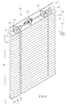
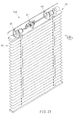
- FIG. 1 is an applied view of a first embodiment of the present invention, showing the transmission mechanism installed in a Venetian blind.
- FIG. 2 is an exploded view of the cord roll-up unit for the transmission mechanism according to the first embodiment of the present invention.
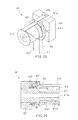
- FIG. 3 is an elevational assembly view of the cord roll-up unit shown in FIG. 2.
- FIG. 4 is a sectional view of the cord roll-up unit shown in FIG. 3.
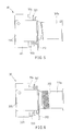
- FIG. 5 and FIG. 6 are schematic drawings showing the cord rolling action of the cord roll-up unit according to the first embodiment of the present invention.
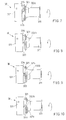
- FIGS. 7∼10 are side views showing the action of the amplitude modulation set, the frequency modulation set, and the clutch according to the first embodiment of the present invention.
- FIGS. 11∼13 are sectional views showing the action of the amplitude modulation set, the frequency modulation set, and the clutch according to the first embodiment of the present invention.
- FIG. 14 is a perspective view in an enlarged scale of the sensor shown in FIG. 1.
- FIGS. 15∼17 are schematic drawings showing the action of the sensor according to the first embodiment of the present invention.
- FIG. 18 is an applied view of a second embodiment of the present invention, showing the transmission mechanism installed in a Venetian blind.
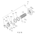
- FIG. 19 is an exploded view of the cord roll-up unit for the transmission mechanism according to the second embodiment of the present invention.
- FIG. 20 is an elevational assembly view of the cord roll-up unit shown in FIG. 19.
- FIG. 21 is a sectional view of the cord roll-up unit shown in FIG. 20.
- FIG. 22 illustrates the lift cord rolling action of the cord roll-up unit according to the second embodiment of the present invention.
- FIG. 23 is an applied view of a third embodiment of the present invention, showing the transmission mechanism installed in a Venetian blind.
- FIG. 24 is an exploded view of the cord roll-up unit for the transmission mechanism according to the third embodiment of the present invention.
- FIG. 25 is an elevational assembly view of the cord roll-up unit shown in FIG. 24.
- FIG. 26 is a sectional view of the cord roll-up unit shown in FIG. 25.
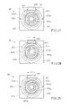
- FIGS. 27∼29 are sectional views showing the action of the cord roll-up unit according to the third embodiment of the present invention.
-
- Referring to FIGS. From 1 through 9, a first preferred embodiment of the present invention provides a
transmission mechanism 100 mountable to a Venetian blind 10 including adriving unit 20. The Venetian blind 10, as shown in FIG. 1, comprises aheadrail 11 and aslat set 12. Theheadrail 11 is mountable to the top side of the window, comprising aninside holding chamber 111, and two throughholes 112 bilaterally disposed at a bottom side in communication with theholding chamber 111. Theslat set 12 is comprised of a plurality ofslats 121 and abottom rail 123. Eachslat 121 has two-wire holes 122 corresponding to the throughholes 112 of theheadrail 11. Because the Venetian blind 10 is of the known art, no further detailed structural description is necessary. - As shown in FIG. 1, the
driving unit 20 comprises areversible motor 21, atransmission shaft 22, asignal transmitter 23, asignal receiver 24, and abattery 25. Themotor 21 is mounted inside theholding chamber 111 of theheadrail 11. Thetransmission shaft 22 is a rod member of non-circular cross section, having one end coupled to themotor 21 for rotation by themotor 21. Thesignal transmitter 23 can be a remote controller or wired controller for providing control signal to thesignal receiver 24. According to the present preferred embodiment, thesignal transmitter 23 is a wireless remote controller. Thesignal receiver 24 is electrically connected to themotor 21, and adapted to control the operation of themotor 21 subject to the nature of the control signal received from thesignal transmitter 23. Thebattery 25 can be a storage battery, dry battery, planar battery, cylindrical battery, or mercury battery mounted inside theholding chamber 111 and electrically connected to themotor 21 to provide themotor 21 with the necessary working power. - Referring to FIGS. 1∼4 again, the
transmission mechanism 100 comprises two cord roll-up units 30. The cord roll-upunits 30 are respectively mounted inside theholding chamber 111 of theheadrail 11 corresponding to the throughholes 112, each comprised of an amplitude modulation set 31, a frequency modulation set 32, and aclutch 33. - Referring to FIGS. 2∼4, the amplitude modulation set 31 comprises an
amplitude modulation wheel 311, and an amplitudemodulation lift cord 312. Theamplitude modulation wheel 311 is a stepped cylindrical wheel, comprising a head 311b at one end, atail 311e at an opposite end, a body 311c axially connected between the head 311b and thetail 311e, acone 311d axially connected between the body 311c and thetail 311e and disposed corresponding to one throughhole 112 of theheadrail 11, a center throughhole 311a of non-circular cross section axially extended through thetail 311e, thecone 311d, the body 311c and the head 311b and coupled to thetransmission shaft 22 for enabling theamplitude modulation wheel 311 to be rotated with thetransmission shaft 22, and a groove 311f longitudinally extended in the periphery of the head 311b toward the body 311c. As illustrated in FIG. 3, the amplitudemodulation lift cord 312 has one end fixedly connected to afixed point 311g of theamplitude modulation wheel 311, and the other end inserted through one throughhole 112 of theheadrail 11 and onewire hole 122 of eachslat 12 and then fixedly connected to thebottom rail 123. - The frequency modulation set 32 is comprised of a
frequency modulation wheel 321, and a frequencymodulation lift cord 322. Thefrequency modulation wheel 321 comprises an axially extendedcircular hole 321d, abody 321a, and a head 321b. Thebody 321a is provided with anotch 321c. The outer diameter of the head 321b is greater than the outer diameter of thebody 321a. By means of thecircular hole 321d, thefrequency modulation wheel 321 is sleeved onto the body 311c of theamplitude modulation wheel 311, keeping thebody 321a aimed at the head 311b of theamplitude modulation wheel 311. The frequencymodulation lift cord 322 has one end fixedly connected to thefrequency modulation wheel 321, and the other end inserted through one throughhole 112 of theheadrail 11 and fixedly connected to eachslat 12 and thebottom rail 123. - The clutch 33 is comprised of a
support 331, aspring 332, astop block 333, alink 334, and alimiter 335. Thesupport 331 is fixedly mounted inside the holdingchamber 111 of theheadrail 11, having a stepped center through hole formed of a through hole 331a and a recessedhole 331b. The inner diameter of the through hole 331a is smaller than the recessedhole 331b and the outer diameter of theamplitude modulation wheel 311 of the amplitude modulation set 31. The inner diameter of the recessed hole 311b is approximately equal to or slightly greater than the outer diameter of the head 311b of theamplitude modulation wheel 311, such that the head 311b of theamplitude modulation wheel 311 can be inserted into the recessed hole 311b to confine the position of theamplitude modulation wheel 311. Thespring 332 is mounted in the groove 311f of theamplitude modulation wheel 311, having one end stopped at one end of the groove 311f. Thestop block 333 is fixedly fastened to thesupport 331 outside the recessedhole 331b, having asemicircular notch 333a, and twobeveled faces semicircular notch 333a and respectively downwardly sloping from the top toward the recessedhole 331b. Thelink 334 is an oblong key member, having one end inserted into the groove 311f of theamplitude modulation wheel 311 and stopped against thespring 332 and the other end inserted into thenotch 321c of thefrequency modulation wheel 321. Therefore, thelink 334 couples thefrequency modulation wheel 321 to theamplitude modulation wheel 311. Thelimiter 335 is fixedly fastened to thesupport 331, stopping thefrequency modulation wheel 321 from falling out of theamplitude modulation wheel 311. - The operation of the present invention is outlined hereinafter with reference to FIGS. from 5 through 13. When the user operated the
signal transmitter 23 of the drivingunit 20 to transmit a control signal of lifting the Venetian blind, thesignal receiver 24 immediately receives the control signal. Upon receipt of the control signal, thesignal receiver 24 drives themotor 21 to rotate thetransmission shaft 22. Because the center throughhole 311a of theamplitude modulation wheel 311 is a non-circular hole that fits thetransmission shaft 22, rotating thetransmission shaft 22 causes theamplitude modulation wheel 311 to be synchronously rotated to roll up the amplitudemodulation lift cord 312. During rotary motion, theamplitude modulation wheel 311 moves axially in thesupport 331, keeping the amplitudemodulation lift cord 312 to be smoothly wound round the periphery of theamplitude modulation wheel 311 from the conical surface of thecone 311d toward thetail 311e (see FIGS. 5 and 6). When the amplitude modulation wheel b rolling up the amplitudemodulation lift cord 312, thebottom rail 123 is lifted, thereby causing theslats 121 to be received and moved with thebottom rail 123 upwards toward theheadrail 11 to the desired elevation. - Because the
link 334 of the clutch 33 links thefrequency modulation wheel 321 and theamplitude modulation wheel 311 at this time, thefrequency modulation wheel 321 is rotated with the amplitude modulation wheel 311 (see FIGS. 7 and 11). During rotary motion of thefrequency modulation wheel 321, the frequencymodulation lift cord 322 is moved, causing theslats 121 to be tilted. When thefrequency modulation wheel 321 turned to a predetermined position (the position where thelink 334 touches thebeveled face 333b of the stop block 333 (see FIGS. 8and 12), thelink 334 moves along thebeveled face 333b toward the recessedhole 331b (see FIG. 9) to compress thespring 332, thereby causing thelink 334 to be forced out of thenotch 321c of the frequency modulation wheel 321 (see FIG. 10) to disconnect thefrequency modulation wheel 321 from theamplitude modulation wheel 311. Therefore, when thefrequency modulation wheel 321 rotated to this angle, it is disengaged from theamplitude modulation wheel 311. At this time, thetransmission shaft 22 continuously rotates theamplitude modulation wheel 311 to roll up the amplitudemodulation lift cord 312 and to receive theslats 121 without changing the tilting angle of theslats 121. - When releasing the
slats 121, operates thesignal transmitter 23 to transmit a control signal of releasing the slats to thesignal receiver 24. Upon receipt of the signal, thesignal receiver 24 immediately drives themotor 21 to rotate in the reversed direction, thereby causing thetransmission shaft 22 and theamplitude modulation wheel 311 to be rotated in the same direction. Reverse rotation of theamplitude modulation wheel 311 lets off the amplitudemodulation lift cord 312, and therefore thebottom rail 123 and theslats 121 are lowered to extend out theVenetian blind 10. At the initial stage during rotary motion of theamplitude modulation wheel 311, thebeveled face 333b of thestop block 333 keeps thefrequency modulation wheel 321 out of theamplitude modulation wheel 311. However, when thelink 334 reversed with theamplitude modulation wheel 311 to thebeveled face 333b again, the spring power of thespring 332 forces thelink 334 into thenotch 321c, thereby causing thefrequency modulation wheel 321 and theamplitude modulation wheel 311 to be linked again. At this time, thefrequency modulation wheel 321 is rotated with theamplitude modulation wheel 311 to tilt thebottom rail 123 and theslats 121. When thelink 334 moved to the otherbeveled face 333c, thebeveled face 333c forces thelink 334 away from thefrequency modulation wheel 321 to disconnect theamplitude modulation wheel 311 from thefrequency modulation wheel 321. At this time, thetransmission shaft 22 continuously rotates theamplitude modulation wheel 311 to let off the amplitudemodulation lift cord 312 and to release theslats 121 without changing the tilting angle of theslats 121. - With respect to the tilting of the
slats 121, the operation is described hereinafter. At first, the user operates thesignal transmitter 23 to transmit a slat tilting control signal to thesignal receiver 24. Upon receipt of the control signal, thesignal receiver 24 immediately drives themotor 21 to rotate thetransmission shaft 22 and theamplitude modulation wheel 311, and to further forces thelink 334 into engagement with theamplitude modulation wheel 311 and thefrequency modulation wheel 321, permitting synchronous rotation of thefrequency modulation wheel 321 with theamplitude modulation wheel 311 to let off the frequencymodulation lift cord 322 and to further control the tilting angle of theslats 121. In actual practice, it is not necessary to tilt theslats 121 at a wide angle, therefore the angle of rotation of thefrequency modulation wheel 311 can be limited to a limited range. According to the present preferred embodiment, thefrequency modulation wheel 321 is rotatable with theamplitude modulation wheel 311 within about 180°. Thestop block 333 limits the angle of rotation of thefrequency modulation wheel 311. When theslats 121 tilted to the desired angle, themotor 21 is stopped. (during the aforesaid slat angle tilting control operation, the amount of upward or downward movement of thebottom rail 11 due to rotation of theamplitude modulation wheel 311 is insignificant, without affecting the reliability of the operation). - Referring to FIG. 1 and FIGS. from 14 through 17, the
transmission mechanism 100 further comprises asensor 40 installed in the middle of thetransmission shaft 22. When theslats 121 moved to the upper limit or lower limit position, thesensor 40 is induced to stop themotor 21. According to the present preferred embodiment, thesensor 40 comprises a mountingplate 41, a locatingblock 42, awheel 43, and twolimit switches plate 41 is fixedly fastened to the peripheral wall of the holdingchamber 111 of theheadrail 11. The locatingblock 42 is fixedly mounted inside the holdingchamber 111 of theheadrail 11. having acenter screw hole 421. Thewheel 43 is coupled to thetransmission shaft 22 for synchronous rotation, having anouter thread 431 threaded into thecenter screw hole 421 of the locatingblock 42. Rotation of thetransmission shaft 22 causes synchronous rotation of thewheel 43 with thetransmission shaft 22 and axial movement of thewheel 43 in the locatingblock 42. The limit switches 44, 45 are respectively mounted on the mountingplate 41 at two sides relative to the wheel 43 (at the ends of path for axial movement of thewheel 42 of thesensor 40 corresponding to the upper limit position and lower limit position of theslats 121 of the Venetian blind 10), and electrically connected to themotor 21. When theslats 121 moved to the upper or lower limit position, thewheel 43 touches onelimit switch limit switch motor 21. - The structure and function of the present invention are well understood from the aforesaid detailed description. The advantages of the present invention are outlined hereinafter.
- 1. Slat lifting and tilting dual-control function:
- The clutch is controlled to couple the amplitude modulation wheel, which controls lifting of the slats, and the frequency modulation wheel, which controls tilting of the slats, enabling the amplitude modulation wheel and the frequency modulation wheel to be driven by the same driving source to lift or tilt the slats.
- 2. Single drive source and compact size:
- Because a clutch is used to couple the amplitude modulation wheel and the frequency modulation wheel, one single driving source is sufficient to drive the amplitude modulation wheel and the frequency modulation wheel. Therefore, the transmission mechanism of the present invention is compact and inexpensive, and requires less installation space.
- 3. Durable mechanical design:
- Because the transmission mechanism is provided with a sensor, the motor is immediately stopped when the slats moved to the upper or lower limit position, preventing damage to the parts of the mechanism.
-
- FIGS. 18∼22 show a
transmission mechanism 200 used in aVenetian blind 10 having a drivingunit 20 and asensor 40 according to a second embodiment of the present invention. Thetransmission mechanism 200 comprises two cord roll-upunits 50. Each cord roll-upunit 50 is comprised of an amplitude modulation set 51, a frequency modulation set 52, and a clutch 53. This embodiment is substantially similar to the aforesaid first embodiment of the present invention with the exception of the cord roll-upunits 50. The main features of this second embodiment are outlined hereinafter with reference to FIGS. from 19 through 22. - The
amplitude modulation wheel 511 of the amplitude modulation set 51 comprises anouter thread 511a extended around the periphery, and a longitudinal groove 511b extended in the periphery and cut through theouter thread 511a. Thefrequency modulation wheel 521 of the frequency modulation set 52 comprises abody 521a having a peripheral notch 521b. - The clutch 53 is comprised of a
support 531, aspring 532, apressure ring 533, astop block 534, alink 535, and alimiter 536. Thesupport 531 is fixedly mounted inside the holdingchamber 111 of theheadrail 11, having a stepped center through hole formed of a throughhole 531a and a recessedhole 531b. The throughhole 531a has a threadedsection 531c threaded onto theouter thread 511a of theamplitude modulation wheel 511 of the amplitude modulation set 51. Thespring 532 is sleeved onto theamplitude modulation wheel 511 and supported in between the throughhole 531a and the recessedhole 531b. Thepressure ring 533 is sleeved onto theamplitude modulation wheel 511 and stopped at thespring 532 against thesupport 531. Thestop block 534 is fixedly fastened to thesupport 531 outside the recessedhole 531b and stopped at thepressure ring 533 against thespring 532, having asemicircular notch 534a and twobeveled faces 534b, 534c disposed at two sides of thesemicircular notch 534a and respectively downwardly sloping from the top toward the recessedhole 531b. Thelink 535 is an angled key member, having one end inserted into the longitudinal groove 511b of theamplitude modulation wheel 511 and stopped against thepressure ring 533 and thespring 532 and the other end inserted into the peripheral notch 521b of thefrequency modulation wheel 521. Therefore, thelink 535 couples thefrequency modulation wheel 521 to theamplitude modulation wheel 511. Thelimiter 536 is fixedly fastened to thesupport 531, stopping thefrequency modulation wheel 521 from falling out of theamplitude modulation wheel 511. - According to the aforesaid second embodiment of the present invention, the
link 535 couples thefrequency modulation wheel 521 to theamplitude modulation wheel 511 for synchronous rotation. Further, by means of the relative action between thelink 535 and the beveled faces 534b, 534c, theamplitude modulation wheel 511 is disconnected from thefrequency modulation wheel 521. Therefore, one single driving source is sufficient to achieve amplitude modulation control and frequency modulation control. Further, because theamplitude modulation wheel 511 is coupled to thesupport 531 by a screw joint, theamplitude modulation wheel 511 is moved axially when rotated, keeping the amplitudemodulation lift cord 512 smoothly wound round the periphery of the amplitude modulation wheel 511 (see FIG. 22). - FIGS. 23∼29 show a
transmission mechanism 300 used in aVenetian blind 10 having a drivingunit 20 and asensor 40 according to a third embodiment of the present invention. Thetransmission mechanism 300 comprises two cord roll-upunits 60. Each cord roll-upunit 60 is comprised of an amplitude modulation set 61, a frequency modulation set 62, and a clutch 63. Similarly, the amplitude modulation set 61 is comprised of anamplitude modulation wheel 611 and an amplitudemodulation lift cord 612. The main features of this third embodiment are outlined hereinafter with reference to FIGS. from 24 through 26. - The
amplitude modulation wheel 611 of the amplitude modulation set 61 is formed of acylindrical wheel body 613, abobbin 614, and astop key 615. Thewheel body 613 comprises acoupling portion 613b, a bearingportion 613d axially connected to thecoupling portion 613b in a line, acollar 613c extended around the periphery of the connection area between thecoupling portion 613b and the bearingportion 613d, a center throughhole 613a of non-circular cross-section axially extended through the front and rear ends thereof and coupled to thetransmission shaft 22 of the drivingunit 20 for enabling thewheel body 613 to be synchronously rotated with thetransmission shaft 22, and a recessedhole 613e disposed in the periphery of the bearingportion 613d adjacent thecollar 613c. Thestop key 615 is mounted in the recessedhole 613e and partially protruding over the outside wall of the bearingportion 613d. Thebobbin 614 comprises a first inner hole 614a and a second inner hole 614b respectively axially extended from the two distal ends thereof toward each other, a protruded block 614c suspended in the second inner hole 614b, and a conical face 614d extended around the periphery at one end. The diameter of the first inner hole 614a is approximately equal to the outer diameter of the bearingportion 613d of thewheel body 613. The diameter of the second inner hole 614b is greater than the outer diameter of the bearingportion 613d of thewheel body 613. The bearingportion 613d of thewheel body 613 is inserted through the second inner hole 614b into the first inner hole 614a. When the amplitude modulation wheel 6111 assembled, the periphery of the bearingportion 613d is equally spaced from the peripheral wall of the second inner hole 614b of thebobbin 614, and the protruded block 614c is suspended in the second inner hole 614b around and without touching the periphery of the bearingportion 613d. When rotating thecylindrical wheel body 613 relative to thebobbin 614 in one direction, thestop key 615 will be forced into contact with the protruded block 614c. Continuously rotation of thecylindrical wheel body 613 after contact between thestop key 615 and the protruded block 614c causes synchronous rotation of thebobbin 614 with thecylindrical wheel body 613. The amplitudemodulation lift cord 612 has one end fixedly fastened to thebobbin 614. When rotating thebobbin 614 to roll up the amplitudemodulation lift cord 612, the conical face 614d guides the winding of the amplitudemodulation lift cord 612 round the periphery of thebobbin 614 smoothly. - The frequency modulation set 62 is comprised of a
frequency modulation wheel 621 and a frequencymodulation lift cord 622. Thefrequency modulation wheel 621 has a center throughhole 621b coupled to thecoupling portion 613b of thecylindrical wheel body 613 of theamplitude modulation wheel 611, and aprotrusion 621a protruded from one side thereof. - The clutch 63 is comprised of a
support 631, aspring 632, and alimiter 633. Thesupport 631 is fixedly mounted inside the holdingchamber 111 of theheadrail 11, having a stepped center through hole formed of a throughhole 631a and a recessed hole 631b and twoshoulders protrusion 621a of thefrequency modulation wheel 621 alternatively. Thespring 632 is mounted in the recessed hole 631b of thesupport 631, having one end stopped at the connection area between the recessed hole 631b and the throughhole 631a and the other end stopped at thefrequency modulation wheel 621. Thelimiter 633 is fixedly fastened to thesupport 631, stopping thefrequency modulation wheel 621 from falling out of theamplitude modulation wheel 611. - According to the aforesaid third embodiment of the present invention, the spring power of the
spring 632 forces thefrequency modulation wheel 621 into friction-engagement with thecollar 613c of thecylindrical wheel body 613 of theamplitude modulation wheel 611 for synchronous rotation. When theprotrusion 621a of thefrequency modulation wheel 621 stopped at oneshoulder support 631, the resisting force between theprotrusion 621a and thecorresponding shoulder frequency modulation wheel 621 and thecollar 613c of thecylindrical wheel body 613 of theamplitude modulation wheel 611. At this time, thefrequency modulation wheel 621 is stopped at thecorresponding shoulder amplitude modulation wheel 611 is continuously rotated. Therefore, one single driving source is sufficient to achieve amplitude modulation control and frequency modulation control. - Referring to FIGS. 27∼29, at the initial stage of the rotary motion of the
cylindrical wheel body 613 with thetransmission shaft 22, the protruded block 614c of thebobbin 614 does not touch the stop key 615 (see FIG. 27). At this time, thecylindrical wheel body 613 runs idle without moving thebobbin 614. When thestop key 615 moved with thecylindrical wheel body 613 into contact with the protruded block 614c of thebobbin 614 during rotary motion of the cylindrical wheel body 613 (see FIG. 28 or FIG. 29), thebobbin 614 is rotated with thecylindrical wheel body 613 to roll up the amplitudemodulation lift cord 612. Therefore, when controlling the tilting angle of the slats, thebobbin 614 does no work, i.e., the elevation of the bottom rail is maintained unchanged when adjusting the angle of the slats.
Claims (24)
- A transmission mechanism mounted in a motor-driven Venetian blind and adapted to be driven by a driving unit for controlling lifting/lowering of slats of said Venetian blind and tilting of said slats, the transmission mechanism comprising:wherein the amplitude modulation set has an amplitude modulation wheel coupled to said driving unit, and an amplitude modulation lift cord coupled to said amplitude modulation wheel and said slats and adapted to lift/lower said slats of said Venetian blind while the amplitude modulation wheel is driven by the driving unit to rotate;at least one cord roll-up unit having an amplitude modulation set, a frequency modulation set and a clutch;
wherein the frequency modulation set has a frequency modulation wheel being capable of synchronous rotation with said amplitude modulation wheel through said clutch, and a lift cord coupled to said frequency modulation wheel and said slats and adapted to tilt said slats of said Venetian blind through the rotation of the frequency modulation wheel driven by the amplitude modulation wheel;
wherein the clutch is capable of releasing the synchronous rotation between the frequency modulation wheel and the amplitude modulation wheel while the clutch is performed to a predetermined position. - The transmission mechanism as claimed in claim 1 further comprising a sensor adapted to turn off said driving unit when said slats of said Venetian blind lifted to an upper limit position or lowered to a lower limit position.
- The transmission mechanism as claimed in claim 2, wherein said sensor comprises a mounting plate fixedly mounted in said Venetian blind, a locating block fixedly supported on said mounting plate, two limit switches bilaterally mounted on said mounting plate and electrically connected to said driving unit, a wheel threaded into said locating block and coupled to said driving unit for rotation and axial movement between said limit switches upon operation of said driving unit to trigger one of said limit switches to cut off power supply from said driving unit when said slats of said Venetian blind moved to the lower/upper limit position.
- The transmission mechanism as claimed in claim 1, wherein said amplitude modulation wheel is a stepped cylindrical member, having a center through hole of non-circular cross-section extended through two distal ends thereof and coupled to said driving unit for enabling said amplitude modulation wheel to be rotated by said driving unit.
- The transmission mechanism as claimed in claim 1, wherein said amplitude modulation wheel comprises a tail adapted for rolling up said amplitude modulation lift cord, and a cone disposed at one end of said tail and adapted for guiding said amplitude modulation lift cord onto said tail.
- The transmission mechanism as claimed in claim 1, wherein said clutch comprises a support having a recessed hole, which receives one end of said amplitude modulation wheel to stop said amplitude modulation wheel from axial displacement.
- The transmission mechanism as claimed in claim 6 wherein said frequency modulation wheel comprises a circular center through hole sleeved onto said amplitude modulation wheel; said clutch further comprises a limiter fixedly fastened to said support to stop said frequency modulation wheel from falling out of said amplitude modulation wheel.
- The transmission mechanism as claimed in claim 6, wherein said amplitude modulation wheel comprises a longitudinal groove disposed in the periphery thereof inside said recessed hole of said support; said frequency modulation wheel comprises a peripheral notch; said clutch further comprises a spring mounted in the longitudinal groove of said amplitude modulation wheel and stopped at one end of said longitudinal groove, and a link supported on one end of said spring in said longitudinal groove of said amplitude modulation wheel and partially engaged into the peripheral notch of said frequency modulation wheel to link said frequency modulation wheel to said amplitude modulation wheel.
- The transmission mechanism as claimed in claim 8, wherein said clutch further comprises a stop block fixedly fastened to one side of said support outside said recessed hole, said stop block comprising a semicircular notch and two beveled faces disposed at two sides of said semicircular notch and respectively downwardly sloping toward said recessed hole of said support and adapted for guiding said link out of said peripheral notch of said frequency modulation wheel into said longitudinal groove of said amplitude modulation wheel to disengage said frequency modulation wheel from said amplitude modulation wheel.
- The transmission mechanism as claimed in claim 9, wherein the position is where said link touches one of said beveled faces.
- The transmission mechanism as claimed in claim 1, wherein said amplitude modulation wheel comprises an outer thread extended around the periphery thereof; said clutch comprises a support, said support having a center through hole and an inner thread extended around said center through hole and threaded onto the outer thread of said amplitude modulation wheel to guide axial movement of said amplitude modulation wheel upon rotary motion of said amplitude modulation wheel for enabling said amplitude modulation lift cord to be wound round said amplitude modulation wheel in good order.
- The transmission mechanism as claimed in claim 11, wherein said amplitude modulation wheel further comprises a longitudinal groove; said frequency modulation wheel comprises a circular center through hole sleeved onto said amplitude modulation wheel, and a peripheral notch; said clutch comprises a link mounted in the longitudinal groove of said amplitude modulation wheel and moved along the longitudinal groove of said amplitude modulation wheel in and out of the periphery notch of said frequency modulation wheel to control linking between said frequency modulation wheel and said amplitude modulation wheel.
- The transmission mechanism as claimed in claim 12, wherein said support comprises a recessed hole disposed in one side thereof in communication with the center through hole of said support; said clutch further comprises a spring mounted around said amplitude modulation wheel and supported in said recessed hole of said support, and a pressure ring mounted around said amplitude modulation wheel and stopped between said spring and said link to force said link into engagement with the peripheral notch of said frequency modulation wheel by means of the effect of the spring power of said spring.
- The transmission mechanism as claimed in claim 11, wherein said clutch further comprises a stop block fixedly fastened to said support, said stop block comprising two beveled faces bilaterally sloping downwards toward the center through hole of said support and adapted for guiding said link out of the peripheral notch of said frequency modulation wheel to disengage said frequency modulation wheel from said amplitude modulation wheel when said frequency modulation wheel rotated to the position where said link touches one of said beveled faces of said stop block.
- The transmission mechanism as claimed in claim 1, wherein said frequency modulation wheel comprises a cylindrical wheel body coupled to said driving unit for rotation upon operation of said driving unit, said cylindrical wheel body having a peripheral notch, a stop key mounted in the peripheral notch of said cylindrical wheel body and partially protruded over the periphery of said cylindrical wheel body, and a bobbin sleeved onto said cylindrical wheel body, said bobbin comprising a first inner hole coupled to said cylindrical wheel body, a second inner hole axially connected to one end of said first inner hole, said second inner hole having a diameter greater than said first inner hole, and a protruded block suspended in said second inner hole corresponding to said stop key for enabling said bobbin to be rotated with said cylindrical wheel body when said stop key rotated with said cylindrical wheel body to touch said protruded block.
- The transmission mechanism as claimed in claim 15, wherein said cylindrical wheel body comprises a center through hole of non-circular cross-section axially extended through two distal ends thereof and coupled to said driving unit for enabling said cylindrical wheel body to be rotated by said driving unit.
- The transmission mechanism as claimed in claim 15, wherein said second inner hole of said bobbin is spaced from the periphery of said cylindrical wheel body at a distance so that said protruded block of said bobbin can be moved with rotary motion of said bobbin relative to said cylindrical wheel body within a limited angle.
- The transmission mechanism as claimed in claim 15, wherein said bobbin comprises a cone extended around the periphery at one end thereof and adapted for guiding said amplitude modulation lift cord onto said bobbin in proper order during rotation of said bobbin with said cylindrical wheel body.
- The transmission mechanism as claimed in claim 15, wherein said cylindrical wheel body comprises a cylindrical bearing portion disposed at one end thereof and inserted through said second inner hole of said bobbin into said first inner hole of said bobbin, said cylindrical bearing portion having an outer diameter approximately equal to said first inner hole of said bobbin.
- The transmission mechanism as claimed in claim 19, wherein said frequency modulation wheel comprises a center through hole; said cylindrical body further comprises a coupling portion axially extended from one end of said bearing portion and inserted through the circular center through hole of said frequency modulation wheel, and a collar extended around the periphery thereof between said bearing portion and said coupling portion and adapted for friction-engagement with said frequency modulation wheel.
- The transmission mechanism as claimed in claim 20, wherein said clutch comprises:a support, said support comprising a recessed hole and a circular center through hole axially connected in a line through two opposite sides thereof, the recessed hole of said support having a diameter greater than the circular center through hole of said support; anda spring mounted in the recessed hole of said support and supported between said support and said frequency modulation wheel to force said frequency modulation wheel against the collar of said cylindrical wheel body of said amplitude modulation wheel.
- The transmission mechanism as claimed in claim21, wherein said clutch further comprises a limiter fixedly fastened to said support to stop said frequency modulation wheel from falling out of said amplitude modulation wheel.
- The transmission mechanism as claimed in claim 21, wherein said frequency modulation wheel comprises a protrusion protruded from one side thereof; said support comprises two shoulders disposed in one side thereof at two sides of the recessed hole of said support and adapted to act with the protrusion of said frequency modulation wheel to limit the angle of rotation of said frequency modulation wheel relative to said amplitude modulation wheel.
- The transmission mechanism as claimed in claim 23, wherein the reactive force produced upon contact between the protrusion of said frequency modulation wheel and one shoulder of said support is greater than the friction resistance between said frequency modulation wheel and the collar of said amplitude modulation wheel.
Priority Applications (1)
| Application Number | Priority Date | Filing Date | Title |
|---|---|---|---|
| EP02255528A EP1388636A1 (en) | 2002-08-07 | 2002-08-07 | Transmission mechanism for a motor-driven blind |
Applications Claiming Priority (1)
| Application Number | Priority Date | Filing Date | Title |
|---|---|---|---|
| EP02255528A EP1388636A1 (en) | 2002-08-07 | 2002-08-07 | Transmission mechanism for a motor-driven blind |
Publications (1)
| Publication Number | Publication Date |
|---|---|
| EP1388636A1 true EP1388636A1 (en) | 2004-02-11 |
Family
ID=30129245
Family Applications (1)
| Application Number | Title | Priority Date | Filing Date |
|---|---|---|---|
| EP02255528A Withdrawn EP1388636A1 (en) | 2002-08-07 | 2002-08-07 | Transmission mechanism for a motor-driven blind |
Country Status (1)
| Country | Link |
|---|---|
| EP (1) | EP1388636A1 (en) |
Cited By (3)
| Publication number | Priority date | Publication date | Assignee | Title |
|---|---|---|---|---|
| CN101592020B (en) * | 2008-05-27 | 2011-08-10 | 威海利美佳功能窗有限公司 | Electric shutter blind |
| CN105604471A (en) * | 2016-03-23 | 2016-05-25 | 浙江勇辉电器有限公司 | Domestic electric hoisting device |
| CN108661533A (en) * | 2018-07-25 | 2018-10-16 | 江苏赛迪乐节能科技有限公司 | The withdrawing rope device of shutter embedded in hollow glass |
Citations (5)
| Publication number | Priority date | Publication date | Assignee | Title |
|---|---|---|---|---|
| DE3625365A1 (en) * | 1986-07-26 | 1988-02-04 | Warema Renkhoff Gmbh & Co Kg | Turning device for a slatted blind which can be gathered up and has three slat positions |
| US5103888A (en) | 1990-12-28 | 1992-04-14 | Tachikawa Corporation | Blind slats lifting device |
| JPH05321546A (en) * | 1992-05-26 | 1993-12-07 | Sekisui Jushi Co Ltd | Tilting device of blind slat |
| JPH08246767A (en) * | 1995-03-07 | 1996-09-24 | Yoshio Hirata | Automatic lifting gear of blind |
| DE19803678A1 (en) * | 1997-01-31 | 1998-08-06 | Cherubini Italo | Adjustment for curtain, with drive axle operated by crank |
-
2002
- 2002-08-07 EP EP02255528A patent/EP1388636A1/en not_active Withdrawn
Patent Citations (5)
| Publication number | Priority date | Publication date | Assignee | Title |
|---|---|---|---|---|
| DE3625365A1 (en) * | 1986-07-26 | 1988-02-04 | Warema Renkhoff Gmbh & Co Kg | Turning device for a slatted blind which can be gathered up and has three slat positions |
| US5103888A (en) | 1990-12-28 | 1992-04-14 | Tachikawa Corporation | Blind slats lifting device |
| JPH05321546A (en) * | 1992-05-26 | 1993-12-07 | Sekisui Jushi Co Ltd | Tilting device of blind slat |
| JPH08246767A (en) * | 1995-03-07 | 1996-09-24 | Yoshio Hirata | Automatic lifting gear of blind |
| DE19803678A1 (en) * | 1997-01-31 | 1998-08-06 | Cherubini Italo | Adjustment for curtain, with drive axle operated by crank |
Non-Patent Citations (2)
| Title |
|---|
| PATENT ABSTRACTS OF JAPAN vol. 018, no. 143 (M - 1574) 9 March 1994 (1994-03-09) * |
| PATENT ABSTRACTS OF JAPAN vol. 1997, no. 01 31 January 1997 (1997-01-31) * |
Cited By (3)
| Publication number | Priority date | Publication date | Assignee | Title |
|---|---|---|---|---|
| CN101592020B (en) * | 2008-05-27 | 2011-08-10 | 威海利美佳功能窗有限公司 | Electric shutter blind |
| CN105604471A (en) * | 2016-03-23 | 2016-05-25 | 浙江勇辉电器有限公司 | Domestic electric hoisting device |
| CN108661533A (en) * | 2018-07-25 | 2018-10-16 | 江苏赛迪乐节能科技有限公司 | The withdrawing rope device of shutter embedded in hollow glass |
Similar Documents
| Publication | Publication Date | Title |
|---|---|---|
| US6659156B2 (en) | Screw transmission mechanism for a blind | |
| US6619365B1 (en) | Plug-in transmission mechanism for a motor-driven blind | |
| US6655441B2 (en) | Friction transmission mechanism for a motor-driven blind | |
| US20040194897A1 (en) | Friction transmission mechanism for a motor-driven blind | |
| CA2437775C (en) | Window blind having multiple driving modes | |
| US20220389758A1 (en) | Axially driven wand for a window blind | |
| US20040163774A1 (en) | Venetian blind having dual-drive mechanism | |
| CA2421479A1 (en) | Blind lifting control method and mechanism | |
| US11713620B2 (en) | Blind control having a narrow profile drive | |
| CA2437347A1 (en) | Window blind control structure | |
| EP1435425A3 (en) | Blind lifting control method and mechanism | |
| JP3861034B2 (en) | Blind clutch transmission structure | |
| CA2983527A1 (en) | Blind control having a narrow profile drive | |
| AU783387B2 (en) | Plug-in transmission mechanism for a blind | |
| JP4202211B2 (en) | blind | |
| AU783391B2 (en) | Screw transmission mechanism for a blind | |
| JP4801112B2 (en) | blind | |
| EP1500777A1 (en) | Window blind having multiple driving modes | |
| JP4166652B2 (en) | blind | |
| AU783390B2 (en) | Friction transmission mechanism for a blind | |
| KR100517274B1 (en) | Transmission mechanism for a blind | |
| EP1371807A1 (en) | Electromagnetic clutch-controlled electric blind | |
| AU783399B2 (en) | Electromagnetic clutch-controlled electric blind | |
| EP1045955B1 (en) | A pulling cord device for venetian blinds and the like | |
| CN213510366U (en) | Drawing rope controller for louver window |
Legal Events
| Date | Code | Title | Description |
|---|---|---|---|
| PUAI | Public reference made under article 153(3) epc to a published international application that has entered the european phase |
Free format text: ORIGINAL CODE: 0009012 |
|
| 17P | Request for examination filed |
Effective date: 20020829 |
|
| AK | Designated contracting states |
Kind code of ref document: A1 Designated state(s): AT BE BG CH CY CZ DE DK EE ES FI FR GB GR IE IT LI LU MC NL PT SE SK TR |
|
| AX | Request for extension of the european patent |
Extension state: AL LT LV MK RO SI |
|
| AKX | Designation fees paid |
Designated state(s): AT BE BG CH CY CZ DE DK EE ES FI FR GB GR IE IT LI LU MC NL PT SE SK TR |
|
| 17Q | First examination report despatched |
Effective date: 20070329 |
|
| GRAP | Despatch of communication of intention to grant a patent |
Free format text: ORIGINAL CODE: EPIDOSNIGR1 |
|
| STAA | Information on the status of an ep patent application or granted ep patent |
Free format text: STATUS: THE APPLICATION IS DEEMED TO BE WITHDRAWN |
|
| 18D | Application deemed to be withdrawn |
Effective date: 20080326 |