EP1388507A1 - Method and device for forming groups of products - Google Patents
Method and device for forming groups of products Download PDFInfo
- Publication number
- EP1388507A1 EP1388507A1 EP03102388A EP03102388A EP1388507A1 EP 1388507 A1 EP1388507 A1 EP 1388507A1 EP 03102388 A EP03102388 A EP 03102388A EP 03102388 A EP03102388 A EP 03102388A EP 1388507 A1 EP1388507 A1 EP 1388507A1
- Authority
- EP
- European Patent Office
- Prior art keywords
- conveying
- input
- conveyor
- branch
- return
- Prior art date
- Legal status (The legal status is an assumption and is not a legal conclusion. Google has not performed a legal analysis and makes no representation as to the accuracy of the status listed.)
- Granted
Links
- 238000000034 method Methods 0.000 title claims abstract description 14
- 230000000295 complement effect Effects 0.000 claims abstract description 8
- 230000005540 biological transmission Effects 0.000 claims 13
- 235000019506 cigar Nutrition 0.000 description 22
- 241000826860 Trapezium Species 0.000 description 3
- 241000208125 Nicotiana Species 0.000 description 2
- 235000002637 Nicotiana tabacum Nutrition 0.000 description 2
- 230000001133 acceleration Effects 0.000 description 2
- 238000004519 manufacturing process Methods 0.000 description 2
- 238000011144 upstream manufacturing Methods 0.000 description 2
- 230000008878 coupling Effects 0.000 description 1
- 238000010168 coupling process Methods 0.000 description 1
- 238000005859 coupling reaction Methods 0.000 description 1
- 238000010586 diagram Methods 0.000 description 1
- 238000004904 shortening Methods 0.000 description 1
Images

Classifications
-
- B—PERFORMING OPERATIONS; TRANSPORTING
- B65—CONVEYING; PACKING; STORING; HANDLING THIN OR FILAMENTARY MATERIAL
- B65G—TRANSPORT OR STORAGE DEVICES, e.g. CONVEYORS FOR LOADING OR TIPPING, SHOP CONVEYOR SYSTEMS OR PNEUMATIC TUBE CONVEYORS
- B65G47/00—Article or material-handling devices associated with conveyors; Methods employing such devices
- B65G47/34—Devices for discharging articles or materials from conveyor
- B65G47/46—Devices for discharging articles or materials from conveyor and distributing, e.g. automatically, to desired points
- B65G47/51—Devices for discharging articles or materials from conveyor and distributing, e.g. automatically, to desired points according to unprogrammed signals, e.g. influenced by supply situation at destination
- B65G47/5104—Devices for discharging articles or materials from conveyor and distributing, e.g. automatically, to desired points according to unprogrammed signals, e.g. influenced by supply situation at destination for articles
- B65G47/5109—Devices for discharging articles or materials from conveyor and distributing, e.g. automatically, to desired points according to unprogrammed signals, e.g. influenced by supply situation at destination for articles first In - First Out systems: FIFO
- B65G47/5113—Devices for discharging articles or materials from conveyor and distributing, e.g. automatically, to desired points according to unprogrammed signals, e.g. influenced by supply situation at destination for articles first In - First Out systems: FIFO using endless conveyors
- B65G47/5118—Devices for discharging articles or materials from conveyor and distributing, e.g. automatically, to desired points according to unprogrammed signals, e.g. influenced by supply situation at destination for articles first In - First Out systems: FIFO using endless conveyors with variable accumulation capacity
- B65G47/5122—Devices for discharging articles or materials from conveyor and distributing, e.g. automatically, to desired points according to unprogrammed signals, e.g. influenced by supply situation at destination for articles first In - First Out systems: FIFO using endless conveyors with variable accumulation capacity by displacement of the conveyor-guiding means, e.g. of the loose pulley-type
-
- B—PERFORMING OPERATIONS; TRANSPORTING
- B65—CONVEYING; PACKING; STORING; HANDLING THIN OR FILAMENTARY MATERIAL
- B65G—TRANSPORT OR STORAGE DEVICES, e.g. CONVEYORS FOR LOADING OR TIPPING, SHOP CONVEYOR SYSTEMS OR PNEUMATIC TUBE CONVEYORS
- B65G47/00—Article or material-handling devices associated with conveyors; Methods employing such devices
- B65G47/02—Devices for feeding articles or materials to conveyors
- B65G47/04—Devices for feeding articles or materials to conveyors for feeding articles
- B65G47/06—Devices for feeding articles or materials to conveyors for feeding articles from a single group of articles arranged in orderly pattern, e.g. workpieces in magazines
- B65G47/08—Devices for feeding articles or materials to conveyors for feeding articles from a single group of articles arranged in orderly pattern, e.g. workpieces in magazines spacing or grouping the articles during feeding
- B65G47/082—Devices for feeding articles or materials to conveyors for feeding articles from a single group of articles arranged in orderly pattern, e.g. workpieces in magazines spacing or grouping the articles during feeding grouping articles in rows
-
- B—PERFORMING OPERATIONS; TRANSPORTING
- B65—CONVEYING; PACKING; STORING; HANDLING THIN OR FILAMENTARY MATERIAL
- B65G—TRANSPORT OR STORAGE DEVICES, e.g. CONVEYORS FOR LOADING OR TIPPING, SHOP CONVEYOR SYSTEMS OR PNEUMATIC TUBE CONVEYORS
- B65G2201/00—Indexing codes relating to handling devices, e.g. conveyors, characterised by the type of product or load being conveyed or handled
- B65G2201/02—Articles
-
- B—PERFORMING OPERATIONS; TRANSPORTING
- B65—CONVEYING; PACKING; STORING; HANDLING THIN OR FILAMENTARY MATERIAL
- B65G—TRANSPORT OR STORAGE DEVICES, e.g. CONVEYORS FOR LOADING OR TIPPING, SHOP CONVEYOR SYSTEMS OR PNEUMATIC TUBE CONVEYORS
- B65G2201/00—Indexing codes relating to handling devices, e.g. conveyors, characterised by the type of product or load being conveyed or handled
- B65G2201/02—Articles
- B65G2201/0214—Articles of special size, shape or weigh
- B65G2201/0217—Elongated
Definitions
- the present invention relates to a method of forming groups of products.
- the present invention may be used to particular advantage in the tobacco industry for processing cigars coming off a production machine, to which the following description refers purely by way of example.
- cigars coming off a production machine are normally collected in containers, from which they are removed manually and divided into groups, each comprising a given number of cigars; and the groups are then placed inside boxes in one or more superimposed layers to form respective boxes of cigars.
- the present invention also relates to a device for forming groups of products.
- a device for forming groups of products as claimed in Claim 8 and, preferably, in any one of the following Claims depending directly or indirectly on Claim 8.
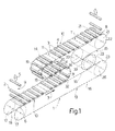
- Number 1 in Figure 1 indicates as a whole a conveying device for receiving, at an input 6, a continuous input succession 2 of cigars 3 arranged with their respective longitudinal axes 4 crosswise to their feed direction 5.
- Cigars 3 in input succession 2 may obviously be fed to input 6 by a conveyor (not shown), or by a transfer device (not shown) for feeding cigars 3 to input 6 one at a time at a given constant rate.
- Conveying device 1 feeds cigars 3 to an output 8 in a travelling direction 7 also crosswise to longitudinal axes 4; compensates for any accidental input gaps 9 in input succession 2, each caused by a missing cigar 3; and divides cigars 3 into groups 10, each defined, in the example shown, by a succession of five cigars 3, and each separated from each adjacent group 10 by an on-line gap 11 corresponding to a missing cigar 3.
- conveying device 1 comprises a plate frame 12 in a plane parallel to travelling direction 7 and crosswise to longitudinal axes 4; and a conveyor 13 comprising a conveying branch 14 extending in travelling direction 7 from input 6 to output 8, and a return branch 15 extending from output 8 to input 6.
- Conveyor 13 comprises an elongated conveying member defined by two facing endless chains 16 looped about a number of pairs of sprockets meshing with chains 16 and supported for rotation by frame 12.
- said pairs of sprockets comprise a first pair of sprockets 17 fitted to frame 12 to rotate idly about a common axis 18 parallel to longitudinal axes 4 and located at input 6; a second pair of sprockets 19 fitted to frame 12 to rotate idly about a common axis 20 parallel to axis 18 and located at an intermediate point along conveying branch 14; a third pair of sprockets 21 fitted to frame 12 to rotate idly about a common axis 22 parallel to axis 18 and located at output 8; and a fourth pair of sprockets 23, which are fitted to an output shaft 24 of a "brushless" motor 25 fitted to frame 12, and rotate with shaft 24 about an axis 26 parallel to axis 18 and located at an intermediate point along return branch 15.
- axes 18, 20, 22 and 26 are located successively at the vertices of a trapezium, with axes 18 and 26 located at the opposite ends of the major base of the trapezium, and axes 18 and 22 located at the opposite ends of a diagonal of the trapezium.
- conveying device 1 also comprises a compensating device 27, in turn comprising a guide 28 fitted to frame 12 in a fixed position between sprockets 17 and 23 on one side and sprockets 19 and 21 on the other, and extending in a direction 28a parallel to a plane defined by axes 18 and 26 and substantially crosswise to conveying branch 14 and return branch 15; and a slide 29 mounted to slide along guide 28, and which is run along guide 28 by a "brushless" motor 30 controlling a rack-and-pinion coupling (not shown) interposed between slide 29 and guide 28.
- a compensating device 27 comprising a guide 28 fitted to frame 12 in a fixed position between sprockets 17 and 23 on one side and sprockets 19 and 21 on the other, and extending in a direction 28a parallel to a plane defined by axes 18 and 26 and substantially crosswise to conveying branch 14 and return branch 15; and a slide 29 mounted to slide along guide 28, and which is run along guide 28 by a "brushless" motor
- Compensating device 27 also comprises a first pair of sprockets 31 fitted to slide 29 to rotate idly about a common axis 32 parallel to axis 18, and externally engaging a portion of conveying branch 14 extending between sprockets 17 and 19; and a second pair of sprockets 33 fitted to slide 29 to rotate idly about a common axis 34 parallel to axis 18, and externally engaging a portion of return branch 15 extending between sprockets 21 and 23.
- Conveyor 13 is fitted with a succession of cigar-holder units 35 interposed between and equally spaced along chains 16.
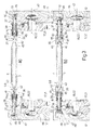
- Each cigar-holder unit 35 comprises two opposite, coaxial gripping members 36, each of which comprises a cylindrical rod 37 parallel to axis 18 and mounted to slide through a respective tubular link-retaining pin 38 of respective chain 16, and through a hole formed through the end wall of a cylindrical cup 39 integral with one end of relative pin 38 and projecting, coaxially with relative rod 37, from relative chain 16 towards the other chain 16.
- Rod 37 projects from the open end of relative cup 39, and is force-fitted inside a dead axial end hole 40 of a relative cylindrical gripping head 41 coaxial with rod 37 and having, on the end facing the other chain 16, a conical seat 42 open on the side facing the other chain 16 and for receiving a respective tapered end 43 of a respective cigar 3 positioned with its longitudinal axis 4 coaxial with rod 37.
- a helical spring 44 coaxial with rod 37, is compressed between gripping head 41 and relative cup 39, and is housed, at one end, inside relative cup 39, and, at the other end, inside an annular groove 45 formed about relative hole 40 and coaxial with rod 37.
- rod 37 projects from the end of relative pin 38 opposite the end connected to relative cup 39, and is fitted on its free end with a tappet 46.
- the length of rods 37 and relative springs 44 is such as to enable relative gripping heads 41 to move - in opposition to relative springs 44 and when outward axial thrust is exerted on relative rods 37 - from a normal closed gripping position (Figure 3b), wherein relative gripping heads 41 are separated by a distance smaller than the length of cigar 3, to an open position ( Figure 3a), wherein relative gripping heads 41 are separated by a distance greater than the length of cigar 3.
- each cam device 47 comprises a plate 48 fitted integrally to frame 12 and having an inner channel 49, which is open at the ends, is travelled along by tappets 46, and communicates externally along its whole length via a slot 50 formed through the surface of plate 48 facing relative chain 16, and through an undulated lateral surface 51 of channel 49.
- Surfaces 51 of plates 48 at input 6 are so shaped as to move relative tappets 46 gradually outwards to open units 35 immediately upstream from input 6 and close them just past input 6.
- surfaces 51 of plates 48 at output 8 are so shaped as to move relative tappets 46 gradually outwards to open units 35 as they move through output 8, and close them just past output 8.
- motor 25 is normally operated at constant speed to feed cigar-holder units 35 to input 6 at the same rate at which cigars 3 in input succession 2 are fed to input 6.
- motor 25 is temporarily accelerated, so that, in the time lapse between the arrival of the last cigar 3 in group 10 and arrival of the next cigar 3, the portion of conveyor 13 travelling through input 6 is fed through by an amount equal to twice the spacing of cigar-holder unit 35, thus forming, on conveyor 13, a gap 11 corresponding to a vacant cigar-holder unit 35 and separating two adjacent groups 10.
- motor 30 sharply accelerates slide 29 to adjust the lengths of conveying branch 14 and return branch 15 in complementary manner, and so maintain a constant travelling speed V1 of conveyor 13 through output 8.
- slide 29 is moved sharply to the right in Figure 2 to shorten return branch 15 and accordingly lengthen conveying branch 14.
- gap 9 is normally compensated on reaching input 6, either by temporarily arresting motor 25, if the missing cigar 3 is one within a relative group 10, or by maintaining a constant speed of motor 25, if gap 9 corresponds to a gap 11.
- gap 9 is compensated by temporarily arresting motor 25, motor 30 is operated to move slide 29 sharply to the left to keep speed V1 constant. This leftward movement of slide 29 is not recovered during operation of conveying device 1, so that, after a given number of gaps 9 are compensated, slide 29 eventually reaches a leftward limit stop, which arrests motor 25 and cuts off supply of input succession 2.
- Sprockets 23 are then made idle, sprockets 17 are locked by a brake not shown, and motor 30 is operated to move slide 29 back to the right-side position.
Landscapes
- Engineering & Computer Science (AREA)
- Mechanical Engineering (AREA)
- Attitude Control For Articles On Conveyors (AREA)
- Specific Conveyance Elements (AREA)
- Manufacturing Of Cigar And Cigarette Tobacco (AREA)
- Heating, Cooling, Or Curing Plastics Or The Like In General (AREA)
- Shaping Of Tube Ends By Bending Or Straightening (AREA)
- Crystals, And After-Treatments Of Crystals (AREA)
Abstract
Description
Claims (15)
- A method of forming groups of products, the method comprising the steps of feeding a substantially continuous input succession (2) of said products (3) to an input (6) of an endless conveyor (13), which comprises a number of product-holder units (35) equally spaced along the conveyor (13), and extends through said input (6) and an output (8), which define, on the conveyor (13), a conveying branch (14) and a return branch (15) of respective lengths; imparting to said conveyor (13) a variable first travelling speed to generate, at said input (6), a succession of equally spaced on-line gaps (11), each corresponding to a relative vacant product-holder unit (35), and to define, along said conveying branch (14), a succession of groups (10) of products (3), each separated from each adjacent said group (10) by a said on-line gap (11); and varying the lengths of said conveying and return branches (14, 15) in complementary manner to impart to said conveyor (13) a constant second speed at said output (8).
- A method as claimed in Claim 1, and comprising the further step of varying the lengths of said conveying and return branches (14, 15) in complementary manner to vary said first speed and compensate for any input gaps (9) in said input succession (2).
- A method as claimed in Claim 2, wherein said first speed is temporarily zeroed at said input (6) and simultaneously with the presence, at said input (6), of a said input gap (9).
- A method as claimed in any one of Claims 1 to 3, wherein said first speed is imparted by a variable-speed motor (25) connected to said return branch (15).
- A method as claimed in Claim 4, wherein the lengths of said conveying and return branches (14, 15) are varied in complementary manner by moving said conveying and return branches (14, 15) transversely and in the same direction.
- A method as claimed in Claim 5, wherein the lengths of said conveying and return branches (14, 15) are varied in complementary manner by moving said conveying and return branches (14, 15) by means of a first and, respectively, a second rotary transmission member (31, 33) carried by a common support (29) movable transversely with respect to the conveying and return branches (14, 15).
- A method as claimed in Claim 6, wherein said second rotary transmission member (33) engages said return branch (15) between said output (8) and a point of connection to said motor (25).
- A device for forming groups of products, the device comprising an endless conveyor (13) having an input (6) and an output (8), which define, along the conveyor (13), a conveying branch (14) and a return branch (15) of respective lengths; said conveyor (13) receiving, at said input (6), a substantially continuous input succession (2) of said products (3), and comprising a number of product-holder units (35) equally spaced along the conveyor (13); first actuating means (25) for imparting to said conveyor (13) a variable first travelling speed, and for generating, at said input (6), a succession of equally spaced on-line gaps (11), each defined by a relative vacant product-holder unit (35) and separating two adjacent said groups (10) of products (3) along said conveying branch (14); and second actuating means (27) for varying the lengths of said conveying and return branches (14, 15) in complementary manner to impart to said conveyor (13) a constant second speed at said output (8).
- A device as claimed in Claim 8, wherein said first actuating means (25) comprise a "brushless" motor (25).
- A device as claimed in Claim 8 or 9, wherein said conveyor (13) comprises first rotary transmission means (23) connected to said first actuating means (25); a number of idle second rotary transmission means (17, 19, 21); and an elongated conveying member (16) looped about said first and second rotary transmission means (23, 17, 19, 21).
- A device as claimed in Claim 10, wherein said first rotary transmission means (23) are connected to the return branch (15).
- A device as claimed in any one of Claims 8 to 11, wherein said second actuating means (27) comprise a powered support (29) movable in a direction (28a) substantially crosswise to said conveying and return branches (14, 15); and a further two rotary transmission means (31, 33) fitted idly to said support (29), and of which a first (31) engages said conveying branch (14), and a second (33) engages said return branch (15).
- A device as claimed in Claim 12, wherein said second further rotary transmission means (33) engages said return branch (15) between said output (8) and said first rotary transmission means (23).
- A device as claimed in Claim 12 or 13, wherein one (19) of said second rotary transmission means (17, 19, 21) engages an intermediate portion of said conveying branch (14), and is located on the opposite side of said first further rotary transmission means (31) to said input (6).
- A device as claimed in any one of Claims 10 to 13, wherein said elongated conveying member (16) comprises two side by side chains (16); and said rotary transmission means (17, 19, 21, 23) and said further rotary transmission means (31, 33) each comprise two coaxial sprockets, each meshing with a respective said chain (16); each said product-holder unit (35) being located between said two chains (16) and crosswise to the chains (16).
Applications Claiming Priority (2)
| Application Number | Priority Date | Filing Date | Title |
|---|---|---|---|
| ITBO20020526 | 2002-08-08 | ||
| IT000526A ITBO20020526A1 (en) | 2002-08-08 | 2002-08-08 | METHOD AND DEVICE FOR THE FORMATION OF GROUPS OF PRODUCTS. |
Publications (2)
| Publication Number | Publication Date |
|---|---|
| EP1388507A1 true EP1388507A1 (en) | 2004-02-11 |
| EP1388507B1 EP1388507B1 (en) | 2006-03-29 |
Family
ID=30130758
Family Applications (1)
| Application Number | Title | Priority Date | Filing Date |
|---|---|---|---|
| EP03102388A Expired - Lifetime EP1388507B1 (en) | 2002-08-08 | 2003-07-31 | Method and device for forming groups of products |
Country Status (7)
| Country | Link |
|---|---|
| US (1) | US6913135B2 (en) |
| EP (1) | EP1388507B1 (en) |
| JP (1) | JP4335605B2 (en) |
| CN (1) | CN1313326C (en) |
| AT (1) | ATE321714T1 (en) |
| DE (1) | DE60304282T2 (en) |
| IT (1) | ITBO20020526A1 (en) |
Cited By (1)
| Publication number | Priority date | Publication date | Assignee | Title |
|---|---|---|---|---|
| EP3065579B1 (en) * | 2013-11-04 | 2022-07-27 | Philip Morris Products S.A. | System and method for transferring rod-shaped articles |
Families Citing this family (13)
| Publication number | Priority date | Publication date | Assignee | Title |
|---|---|---|---|---|
| ITBO20050335A1 (en) * | 2005-05-10 | 2005-08-09 | Gd Spa | METHOD AND UNIT FOR PRODUCT GROUPING |
| CN100410147C (en) * | 2005-06-03 | 2008-08-13 | 浙江圣雷机械有限公司 | Automatic dispensing and conveying mechanism for medicine plate loading |
| FR2889510B1 (en) * | 2005-08-02 | 2007-09-28 | Sidel Sas | METHOD FOR GROUPING BOXES ON A CONVEYOR AND DEVICE FOR IMPLEMENTING SAID METHOD |
| DE202005013552U1 (en) * | 2005-08-27 | 2005-11-03 | Krones Ag | Dynamic storage for buffering and transporting empty bottle, has lower deflection pulleys rotating in essentially horizontal planes and connected with vertical loops by curved guides for conveyor chain |
| CN100462285C (en) * | 2006-02-22 | 2009-02-18 | 广州达意隆包装机械股份有限公司 | A bottle sorting machine |
| ITBO20060210A1 (en) * | 2006-03-24 | 2007-09-25 | Marchesini Group Spa | DYNAMIC LUNG FOR ITEMS, FOR EXAMPLE SYRINGES. |
| CA2563645C (en) * | 2006-10-11 | 2011-05-17 | Pierre Laganiere | Extendable conveyor system |
| ES2566930T3 (en) * | 2009-12-17 | 2016-04-18 | Bobst Mex Sa | Folding and gluing machine |
| CN102673948B (en) * | 2012-05-18 | 2015-04-29 | 奇瑞汽车股份有限公司 | Conveying device |
| DE102012109316A1 (en) * | 2012-10-01 | 2014-04-03 | Mall Herlan Mb Gmbh | Transfer device and transport device for goods and method for operating a transport device |
| CN104340666B (en) * | 2014-10-15 | 2017-07-21 | 凯迈(洛阳)机电有限公司 | A kind of filter bag apparatus for grouping |
| CN110294336B (en) * | 2018-03-21 | 2021-07-27 | 安徽瑞业钢构股份有限公司 | A steel structure material transport machine |
| WO2019223945A1 (en) * | 2018-05-23 | 2019-11-28 | Scalerandi Federico | Food article loading system and method |
Citations (2)
| Publication number | Priority date | Publication date | Assignee | Title |
|---|---|---|---|---|
| CH682385A5 (en) * | 1990-12-14 | 1993-09-15 | Pamag Ag | Packing hoses, sleeves or tubes into boxes |
| GB2330600A (en) * | 1997-10-24 | 1999-04-28 | Marshall Graham Bailey | Improvements in and relating to methods and apparatus for the transport and storage of material |
Family Cites Families (10)
| Publication number | Priority date | Publication date | Assignee | Title |
|---|---|---|---|---|
| US2932376A (en) * | 1958-02-26 | 1960-04-12 | Westinghouse Electric Corp | Automatic transfer unit |
| ATE41399T1 (en) * | 1985-08-20 | 1989-04-15 | Rheon Automatic Machinery Co | PROCEDURE FOR ORDERING AND CONVEYING ROWS OF PRODUCTS. |
| DE3630791C1 (en) * | 1986-09-10 | 1987-10-22 | Bahlsens Keksfabrik | Method and device for conveying piece goods and for organizing their situation |
| NL8801525A (en) * | 1988-06-15 | 1990-01-02 | Werner & Pfleiderer Haton Bv | DEVICE FOR TRANSFERRING ARTICLES FROM A DELIVERY DEVICE TO A RECORDING DEVICE. |
| JP3245746B2 (en) * | 1989-12-08 | 2002-01-15 | エス イー ゲー シュバイツェリッシェ インズストリー‐ゲゼルシャフト | Column forming device for articles, especially chocolate bars |
| EP0438974B1 (en) | 1990-01-25 | 1993-07-28 | Pamag Ag | Method for packaging sleeves or tubes in boxes, and machine for executing the method |
| US5547004A (en) * | 1992-01-28 | 1996-08-20 | Klockner Hansel Tevopharm B.V. | Method and device for arranging a stream of products |
| DE4334238A1 (en) * | 1993-10-04 | 1995-04-06 | Stimpfl Christof | Device for packaging objects |
| CH690646A5 (en) * | 1995-05-09 | 2000-11-30 | Ferag Ag | An apparatus for conveying objects. |
| FR2748461B1 (en) * | 1996-05-07 | 1998-08-07 | Fl Concept | METHOD AND DEVICE FOR PRECISELY POSITIONING PRODUCTS ON A TRANSFER SYSTEM WITH A VIEW TO SUPPLYING A RECEIVING APPARATUS |
-
2002
- 2002-08-08 IT IT000526A patent/ITBO20020526A1/en unknown
-
2003
- 2003-07-31 US US10/632,128 patent/US6913135B2/en not_active Expired - Fee Related
- 2003-07-31 DE DE60304282T patent/DE60304282T2/en not_active Expired - Fee Related
- 2003-07-31 AT AT03102388T patent/ATE321714T1/en not_active IP Right Cessation
- 2003-07-31 EP EP03102388A patent/EP1388507B1/en not_active Expired - Lifetime
- 2003-08-06 JP JP2003287779A patent/JP4335605B2/en not_active Expired - Fee Related
- 2003-08-08 CN CNB031277047A patent/CN1313326C/en not_active Expired - Fee Related
Patent Citations (2)
| Publication number | Priority date | Publication date | Assignee | Title |
|---|---|---|---|---|
| CH682385A5 (en) * | 1990-12-14 | 1993-09-15 | Pamag Ag | Packing hoses, sleeves or tubes into boxes |
| GB2330600A (en) * | 1997-10-24 | 1999-04-28 | Marshall Graham Bailey | Improvements in and relating to methods and apparatus for the transport and storage of material |
Cited By (1)
| Publication number | Priority date | Publication date | Assignee | Title |
|---|---|---|---|---|
| EP3065579B1 (en) * | 2013-11-04 | 2022-07-27 | Philip Morris Products S.A. | System and method for transferring rod-shaped articles |
Also Published As
| Publication number | Publication date |
|---|---|
| CN1493497A (en) | 2004-05-05 |
| ITBO20020526A1 (en) | 2004-02-09 |
| JP4335605B2 (en) | 2009-09-30 |
| DE60304282T2 (en) | 2006-11-09 |
| CN1313326C (en) | 2007-05-02 |
| DE60304282D1 (en) | 2006-05-18 |
| JP2004161493A (en) | 2004-06-10 |
| EP1388507B1 (en) | 2006-03-29 |
| ATE321714T1 (en) | 2006-04-15 |
| US6913135B2 (en) | 2005-07-05 |
| US20040079049A1 (en) | 2004-04-29 |
Similar Documents
| Publication | Publication Date | Title |
|---|---|---|
| US6913135B2 (en) | Method and device for forming groups of products | |
| JP4885137B2 (en) | Device for grouping individual goods | |
| MX2011003560A (en) | Plant for preparing batches of products, bottles or the like. | |
| US7341141B2 (en) | Method and unit for grouping products | |
| JPH04251022A (en) | Device for formation of article group, and for transferring same | |
| JP2005112470A (en) | Division-cum-synchronization-cum-compression equipment | |
| EP3566981A1 (en) | Outfeed device for a packaging assembly and packaging assembly comprising an outfeed device | |
| US10842183B2 (en) | Forming and transporting apparatus for conveying and forming a group of rod-like articles, and feeding apparatus for feeding a group of rod-like articles | |
| JP4267928B2 (en) | Continuous assembling device on conveyor | |
| US6640961B2 (en) | Unit for feeding an ordered succession of products to an unloading station | |
| US5511364A (en) | Apparatus for packing products in preformed bags | |
| JP6280463B2 (en) | Article conveying device | |
| ITBO20060194A1 (en) | APPARATUS FOR FORMING A CONTINUOUS AND FALLED FLOW OF PAPER ROLLS GROUPS AND OTHER PRODUCTS APPROPRIATELY ORIENTED, INITALLY SINGLE OR PRE-PACKAGED, TOWARDS A CONTINUOUS AND HIGH-PRODUCTION OPERATING MACHINE, SUCH AS A BAGER | |
| US4223779A (en) | Automatic transfer mechanism | |
| JP6613228B2 (en) | System and method for conveying rod-shaped articles and arrangement and method for holding rod-shaped articles in a conveyor band | |
| EP0509624A2 (en) | Confection conveyor system with constant-velocity pick-up section and pausing drop section | |
| JP6804337B2 (en) | Relay device | |
| GB2258443A (en) | Method and device for unloading products off a continuously-moving conveyor. | |
| EP0937666B1 (en) | Transmission for product transfer unit | |
| EP1447357B1 (en) | Ordering apparatus for solid articles | |
| RU2734602C1 (en) | Method and device for movement of rod-shaped products of tobacco industry | |
| JP2006225121A (en) | Product integration method and product integration apparatus | |
| US5718324A (en) | Continuous cigarette manufacturing machine | |
| JPH082657A (en) | Conveyor device for aligned supply | |
| WO2020035830A1 (en) | Method and apparatus for conversion of moving stream of oppositely oriented rod-like articles |
Legal Events
| Date | Code | Title | Description |
|---|---|---|---|
| PUAI | Public reference made under article 153(3) epc to a published international application that has entered the european phase |
Free format text: ORIGINAL CODE: 0009012 |
|
| AK | Designated contracting states |
Kind code of ref document: A1 Designated state(s): AT BE BG CH CY CZ DE DK EE ES FI FR GB GR HU IE IT LI LU MC NL PT RO SE SI SK TR |
|
| AX | Request for extension of the european patent |
Extension state: AL LT LV MK |
|
| 17P | Request for examination filed |
Effective date: 20040723 |
|
| 17Q | First examination report despatched |
Effective date: 20040826 |
|
| AKX | Designation fees paid |
Designated state(s): AT BE BG CH CY CZ DE DK EE ES FI FR GB GR HU IE IT LI LU MC NL PT RO SE SI SK TR |
|
| GRAP | Despatch of communication of intention to grant a patent |
Free format text: ORIGINAL CODE: EPIDOSNIGR1 |
|
| GRAS | Grant fee paid |
Free format text: ORIGINAL CODE: EPIDOSNIGR3 |
|
| GRAA | (expected) grant |
Free format text: ORIGINAL CODE: 0009210 |
|
| AK | Designated contracting states |
Kind code of ref document: B1 Designated state(s): AT BE BG CH CY CZ DE DK EE ES FI FR GB GR HU IE IT LI LU MC NL PT RO SE SI SK TR |
|
| PG25 | Lapsed in a contracting state [announced via postgrant information from national office to epo] |
Ref country code: SK Free format text: LAPSE BECAUSE OF FAILURE TO SUBMIT A TRANSLATION OF THE DESCRIPTION OR TO PAY THE FEE WITHIN THE PRESCRIBED TIME-LIMIT Effective date: 20060329 Ref country code: NL Free format text: LAPSE BECAUSE OF FAILURE TO SUBMIT A TRANSLATION OF THE DESCRIPTION OR TO PAY THE FEE WITHIN THE PRESCRIBED TIME-LIMIT Effective date: 20060329 Ref country code: RO Free format text: LAPSE BECAUSE OF FAILURE TO SUBMIT A TRANSLATION OF THE DESCRIPTION OR TO PAY THE FEE WITHIN THE PRESCRIBED TIME-LIMIT Effective date: 20060329 Ref country code: LI Free format text: LAPSE BECAUSE OF FAILURE TO SUBMIT A TRANSLATION OF THE DESCRIPTION OR TO PAY THE FEE WITHIN THE PRESCRIBED TIME-LIMIT Effective date: 20060329 Ref country code: AT Free format text: LAPSE BECAUSE OF FAILURE TO SUBMIT A TRANSLATION OF THE DESCRIPTION OR TO PAY THE FEE WITHIN THE PRESCRIBED TIME-LIMIT Effective date: 20060329 Ref country code: BE Free format text: LAPSE BECAUSE OF FAILURE TO SUBMIT A TRANSLATION OF THE DESCRIPTION OR TO PAY THE FEE WITHIN THE PRESCRIBED TIME-LIMIT Effective date: 20060329 Ref country code: SI Free format text: LAPSE BECAUSE OF FAILURE TO SUBMIT A TRANSLATION OF THE DESCRIPTION OR TO PAY THE FEE WITHIN THE PRESCRIBED TIME-LIMIT Effective date: 20060329 Ref country code: CH Free format text: LAPSE BECAUSE OF FAILURE TO SUBMIT A TRANSLATION OF THE DESCRIPTION OR TO PAY THE FEE WITHIN THE PRESCRIBED TIME-LIMIT Effective date: 20060329 |
|
| REG | Reference to a national code |
Ref country code: GB Ref legal event code: FG4D |
|
| REG | Reference to a national code |
Ref country code: CH Ref legal event code: EP |
|
| REG | Reference to a national code |
Ref country code: IE Ref legal event code: FG4D |
|
| REF | Corresponds to: |
Ref document number: 60304282 Country of ref document: DE Date of ref document: 20060518 Kind code of ref document: P |
|
| PG25 | Lapsed in a contracting state [announced via postgrant information from national office to epo] |
Ref country code: BG Free format text: LAPSE BECAUSE OF FAILURE TO SUBMIT A TRANSLATION OF THE DESCRIPTION OR TO PAY THE FEE WITHIN THE PRESCRIBED TIME-LIMIT Effective date: 20060629 Ref country code: SE Free format text: LAPSE BECAUSE OF FAILURE TO SUBMIT A TRANSLATION OF THE DESCRIPTION OR TO PAY THE FEE WITHIN THE PRESCRIBED TIME-LIMIT Effective date: 20060629 Ref country code: DK Free format text: LAPSE BECAUSE OF FAILURE TO SUBMIT A TRANSLATION OF THE DESCRIPTION OR TO PAY THE FEE WITHIN THE PRESCRIBED TIME-LIMIT Effective date: 20060629 |
|
| PG25 | Lapsed in a contracting state [announced via postgrant information from national office to epo] |
Ref country code: ES Free format text: LAPSE BECAUSE OF FAILURE TO SUBMIT A TRANSLATION OF THE DESCRIPTION OR TO PAY THE FEE WITHIN THE PRESCRIBED TIME-LIMIT Effective date: 20060710 |
|
| PGFP | Annual fee paid to national office [announced via postgrant information from national office to epo] |
Ref country code: FR Payment date: 20060717 Year of fee payment: 4 |
|
| PG25 | Lapsed in a contracting state [announced via postgrant information from national office to epo] |
Ref country code: IE Free format text: LAPSE BECAUSE OF NON-PAYMENT OF DUE FEES Effective date: 20060731 Ref country code: MC Free format text: LAPSE BECAUSE OF NON-PAYMENT OF DUE FEES Effective date: 20060731 |
|
| PGFP | Annual fee paid to national office [announced via postgrant information from national office to epo] |
Ref country code: IT Payment date: 20060731 Year of fee payment: 4 |
|
| PG25 | Lapsed in a contracting state [announced via postgrant information from national office to epo] |
Ref country code: PT Free format text: LAPSE BECAUSE OF FAILURE TO SUBMIT A TRANSLATION OF THE DESCRIPTION OR TO PAY THE FEE WITHIN THE PRESCRIBED TIME-LIMIT Effective date: 20060829 |
|
| PGFP | Annual fee paid to national office [announced via postgrant information from national office to epo] |
Ref country code: DE Payment date: 20060831 Year of fee payment: 4 |
|
| REG | Reference to a national code |
Ref country code: CH Ref legal event code: PL |
|
| NLV1 | Nl: lapsed or annulled due to failure to fulfill the requirements of art. 29p and 29m of the patents act | ||
| ET | Fr: translation filed | ||
| PLBE | No opposition filed within time limit |
Free format text: ORIGINAL CODE: 0009261 |
|
| STAA | Information on the status of an ep patent application or granted ep patent |
Free format text: STATUS: NO OPPOSITION FILED WITHIN TIME LIMIT |
|
| 26N | No opposition filed |
Effective date: 20070102 |
|
| GBPC | Gb: european patent ceased through non-payment of renewal fee |
Effective date: 20070731 |
|
| PG25 | Lapsed in a contracting state [announced via postgrant information from national office to epo] |
Ref country code: GR Free format text: LAPSE BECAUSE OF FAILURE TO SUBMIT A TRANSLATION OF THE DESCRIPTION OR TO PAY THE FEE WITHIN THE PRESCRIBED TIME-LIMIT Effective date: 20060630 Ref country code: DE Free format text: LAPSE BECAUSE OF NON-PAYMENT OF DUE FEES Effective date: 20080201 Ref country code: CZ Free format text: LAPSE BECAUSE OF FAILURE TO SUBMIT A TRANSLATION OF THE DESCRIPTION OR TO PAY THE FEE WITHIN THE PRESCRIBED TIME-LIMIT Effective date: 20060329 |
|
| PG25 | Lapsed in a contracting state [announced via postgrant information from national office to epo] |
Ref country code: GB Free format text: LAPSE BECAUSE OF NON-PAYMENT OF DUE FEES Effective date: 20070731 |
|
| REG | Reference to a national code |
Ref country code: FR Ref legal event code: ST Effective date: 20080331 |
|
| PG25 | Lapsed in a contracting state [announced via postgrant information from national office to epo] |
Ref country code: FI Free format text: LAPSE BECAUSE OF FAILURE TO SUBMIT A TRANSLATION OF THE DESCRIPTION OR TO PAY THE FEE WITHIN THE PRESCRIBED TIME-LIMIT Effective date: 20060329 Ref country code: EE Free format text: LAPSE BECAUSE OF FAILURE TO SUBMIT A TRANSLATION OF THE DESCRIPTION OR TO PAY THE FEE WITHIN THE PRESCRIBED TIME-LIMIT Effective date: 20060329 |
|
| PG25 | Lapsed in a contracting state [announced via postgrant information from national office to epo] |
Ref country code: LU Free format text: LAPSE BECAUSE OF NON-PAYMENT OF DUE FEES Effective date: 20060731 Ref country code: TR Free format text: LAPSE BECAUSE OF FAILURE TO SUBMIT A TRANSLATION OF THE DESCRIPTION OR TO PAY THE FEE WITHIN THE PRESCRIBED TIME-LIMIT Effective date: 20060329 Ref country code: HU Free format text: LAPSE BECAUSE OF FAILURE TO SUBMIT A TRANSLATION OF THE DESCRIPTION OR TO PAY THE FEE WITHIN THE PRESCRIBED TIME-LIMIT Effective date: 20060930 |
|
| PG25 | Lapsed in a contracting state [announced via postgrant information from national office to epo] |
Ref country code: FR Free format text: LAPSE BECAUSE OF NON-PAYMENT OF DUE FEES Effective date: 20070731 |
|
| PG25 | Lapsed in a contracting state [announced via postgrant information from national office to epo] |
Ref country code: CY Free format text: LAPSE BECAUSE OF FAILURE TO SUBMIT A TRANSLATION OF THE DESCRIPTION OR TO PAY THE FEE WITHIN THE PRESCRIBED TIME-LIMIT Effective date: 20060329 |
|
| PG25 | Lapsed in a contracting state [announced via postgrant information from national office to epo] |
Ref country code: IT Free format text: LAPSE BECAUSE OF NON-PAYMENT OF DUE FEES Effective date: 20070731 |