EP1388435A1 - Pneumatic tire - Google Patents
Pneumatic tire Download PDFInfo
- Publication number
- EP1388435A1 EP1388435A1 EP02726424A EP02726424A EP1388435A1 EP 1388435 A1 EP1388435 A1 EP 1388435A1 EP 02726424 A EP02726424 A EP 02726424A EP 02726424 A EP02726424 A EP 02726424A EP 1388435 A1 EP1388435 A1 EP 1388435A1
- Authority
- EP
- European Patent Office
- Prior art keywords
- carcass ply
- bead core
- winding
- bead
- pulling
- Prior art date
- Legal status (The legal status is an assumption and is not a legal conclusion. Google has not performed a legal analysis and makes no representation as to the accuracy of the status listed.)
- Granted
Links
Images


Classifications
-
- B—PERFORMING OPERATIONS; TRANSPORTING
- B60—VEHICLES IN GENERAL
- B60C—VEHICLE TYRES; TYRE INFLATION; TYRE CHANGING; CONNECTING VALVES TO INFLATABLE ELASTIC BODIES IN GENERAL; DEVICES OR ARRANGEMENTS RELATED TO TYRES
- B60C15/00—Tyre beads, e.g. ply turn-up or overlap
- B60C15/06—Flipper strips, fillers, or chafing strips and reinforcing layers for the construction of the bead
-
- B—PERFORMING OPERATIONS; TRANSPORTING
- B60—VEHICLES IN GENERAL
- B60C—VEHICLE TYRES; TYRE INFLATION; TYRE CHANGING; CONNECTING VALVES TO INFLATABLE ELASTIC BODIES IN GENERAL; DEVICES OR ARRANGEMENTS RELATED TO TYRES
- B60C15/00—Tyre beads, e.g. ply turn-up or overlap
- B60C15/0009—Tyre beads, e.g. ply turn-up or overlap features of the carcass terminal portion
- B60C15/0027—Tyre beads, e.g. ply turn-up or overlap features of the carcass terminal portion with low ply turn-up, i.e. folded around the bead core and terminating at the bead core
-
- Y—GENERAL TAGGING OF NEW TECHNOLOGICAL DEVELOPMENTS; GENERAL TAGGING OF CROSS-SECTIONAL TECHNOLOGIES SPANNING OVER SEVERAL SECTIONS OF THE IPC; TECHNICAL SUBJECTS COVERED BY FORMER USPC CROSS-REFERENCE ART COLLECTIONS [XRACs] AND DIGESTS
- Y10—TECHNICAL SUBJECTS COVERED BY FORMER USPC
- Y10T—TECHNICAL SUBJECTS COVERED BY FORMER US CLASSIFICATION
- Y10T152/00—Resilient tires and wheels
- Y10T152/10—Tires, resilient
- Y10T152/10495—Pneumatic tire or inner tube
- Y10T152/10819—Characterized by the structure of the bead portion of the tire
Definitions
- This invention relates to a pneumatic tire, particularly, a heavy duty pneumatic radial tire, and more particularly proposes a technique that a resistance to pull-out of a carcass ply is improved in a structure of a bead portion wherein a side portion of the carcass ply is wound around a bead core embedded in the respective bead portions and substantially along a profile line of the bead core at a cross-section thereof.
- At least one carcass ply is toroidally extended from a tread portion through a sidewall portion to a bead portion, and a side portion of the carcass ply is fixed by winding around a bead core embedded in the respective bead portion from an inside toward an outside in a radial direction of the tire.
- the side portion 102 of the carcass ply 101 is wound around the bead core 103 through relatively soft coating rubber layers therefor, and when a large tensile force is particularly applied to a main body portion of the carcass ply extending between the bead cores, for example, under an action of a load to the tire, these coating rubber layers can not exert a sufficient resistance to pulling-out on the carcass ply and hence ply cords thereof, so that there is a problem that the uncertainty of the carcass ply 101 over the pulling-out still remains.
- an object of the invention to solve the above problems and to provide a pneumatic tire in which the fear of pulling-out the carcass ply is sufficiently removed while sufficiently preventing the occurrence of the bead portion crack resulted from the highly winding-up of the side portion of the carcass ply outward in the radial direction of the tire.
- the pneumatic tire according to the invention comprises a pair of bead portions each including a bead core and a carcass ply extending between the bead cores and winding its side portion around the respective bead core, characterized in that a pulling-out restraint layer for the carcass ply is arranged between the bead core and a winding portion of the carcass ply.
- the occurrence of the crack in the bead portion can sufficiently be prevented by winding the side portion of the carcass ply around the bead core, for example, along a cross-sectional profile line thereof in stead of winding to a higher position outward in the radial direction of the tire, while the pulling-out of the carcass ply can effectively be prevented by arranging the pulling-out restraint layer for the carcass ply between the bead core and the winding portion of the carcass ply, which is different from coating rubbers for the bead core and the carcass ply, to sufficiently support tensile force acting to the main body portion of the carcass ply with the pulling-out restraint layer to thereby reduce strain generated between the bead core and the tumup portion.
- the pulling-out restraint layer is constituted by a rubber composition.
- the rubber composition is preferable to have a JIS A hardness of 20-90, more preferably 40-60.
- JIS A hardness means a numeric value as measured at a test temperature of 20°C by using a durometer hardness test machine of type A defined by JIS K 6253-1993.
- the function of reducing the strain with respect to the repeated input can be developed over a long period of time, while according to the latter case, the rubber composition can develop a proper restraining force against the pulling-out. That is, when Shore A hardness is less than 20, the rubber composition is difficult to develop a function for supporting the sufficient tensile force or a function for reducing the strain, while when it exceeds 90, there is a fear that the pulling-out restraint layer itself is broken relatively prematurely.
- a distance from a winding end of the carcass ply to a surface of the bead core opposite thereto is not less than 0.3 mm but not more than 7 mm, particularly not less than 0.3 mm but not more than 4 mm.
- the winding portion of the carcass ply is provided with one or more bending parts directing to a direction wound around the bead core.
- the carcass ply can be wound so as to further approach to the peripheral face of the bead core, and hence the winding shape thereof can be approximated to an expected shape.
- a distance of radius from a center of the tire to the winding end of the carcass ply is not more than a distance of radius in a position located at an outermost side in the whole winding portion of the carcass ply in the radial direction of the tire.
- the pulling-out restraint layer results in existing at substantially a uniform thickness between the neighboring portion to the winding end and the surface of the bead core, so that the whole of the neighboring portion to the winding end can be equally restrained by the pulling-out restraint layer to largely enhance the total restraining force against the pulling-out.
- neighbored portion to the winding end means a portion extending outward from an inner peripheral edge or an inner peripheral face of the bead core in the radial direction of the tire at a posture of tire inflated under an internal pressure after rim-assembling.
- a distance from the winding end of the carcass ply to a main body portion of the carcass ply extending between the bead cores is not less than 0.1 mm but not more than 5 mm.
- the stress concentrates in the winding end on the occasion of the fall-down deformation of the sidewall portion of the tire under the application of a heavy load to the tire, and there is a fear of generating the separation failure and the cracks, while when it exceeds 5 mm, there is a fear that the pulling-out restraint layer can not sufficiently develop the function of the layer itself.
- the winding portion of the carcass ply is provided with one or more bending parts located approximately in correspondence to comer parts of the bead core having comer parts in its cross section, the restraining force of the carcass ply by the bead core can be more further enhanced.
- numeral 1 is a bead portion and numeral 2 is a bead core embedded in the bead portion 1.
- a cross section shape of a bead core 2 having a ring shape as a whole is hexagonal.
- a side portion of a carcass ply 3 as a skeleton reinforcing layer is wound along substantially a profile line of the cross section of the bead core 2 from an inside of the bead portion 1.
- a pulling-out restraint layer or a rubber composition 6 constituting a part of a stiffener 5 in the figure is arranged between a neighboring portion 4a to a winding end of a winding portion 4, that is, a portion extending outward from an inner peripheral face of the hexagonal bead core 2 in the radial direction in the figure and a surface of the bead core.
- the winding portion 4 is provided with one or more bending parts directing in a direction wound around the bead core 2, three bending parts B in the figure for the purpose of performing the winding so as to approach the winding portion 4 to the surface of the bead core.
- the bead core 2 has comer parts as shown in the figure, it is preferable to arrange the bending parts B in correspondence to the comer parts.
- the winding portion 4 is preferable to be extended straight between the bending parts and at a free end part located from the leading-end bending part toward a top side, respectively.
- At least the neighboring portion 4a to the winding end is extended at substantially a constant distance with respect to the surface of the bead core opposite thereto, for example, substantially in parallel thereto to make the thickness of the rubber composition 6 interposed between the neighboring portion and the bead core substantially uniform for the purpose of enhancing the total restraining force of the rubber composition 6 against the pulling-out of the carcass ply 3.
- the hardness of the rubber composition 6 is made 20-90 as JIS A hardness for the purpose of developing a proper restraining force against the pulling-out.
- a distance h from a winding end 4b of the carcass ply 3 to a surface of the bead core opposite thereto is not less than 0.3 mm but not more than 7 mm.
- a distance from the winding end 4b to a main body portion 7 of the carcass ply extending between the bead cores is not less than 0.1 mm but not more than 5 mm, particularly not less than 0.3 mm but not more than 4 mm.
- an angle of the free end part 4c with respect to the abscissa is 0°.
- an inclination angle of the free end part 4c with respect to the abscissa is preferable to be within a range of -15° to +60°.
- the free end part 4c frequently approaches to the surface of the bead core toward the winding end, so that the restraining force to the carcass ply through the bead core can be gradually enhanced toward the top end and hence the resistance to the pulling-out can be enhanced.
- the rubber composition 6 can sufficiently support the tensile force applied to the main body 7 of the carcass ply as previously mentioned, so that the pulling-out of the carcass ply can be effectively prevented.
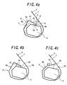
- FIG. 4 is an enlarged section view of a main portion showing another two embodiments according to the invention, in which a case shown by a solid line is that the neighboring portion 4a to the winding end of the winding portion 4, in especial, the free end part 4c located from the leading-end bending part B toward the top end side is particularly extended so as to straightly approach toward the winding end 4b with respect to the bead core surface 2a opposite thereto.
- the similar free end part 4c is extended so as to straightly separate toward the winding end 4b with respect to the bead core surface opposite thereto.
- a distance h from the winding end 4b to the bead core surface opposite thereto is preferable to be within a range of 0.3-7 mm, and a distance d from the winding end 4b to the main body portion 7 of the carcass ply is preferable to be within a range of 0.1-5 mm.
- the inclination angle of the free end part 4c with respect to the bead core surface opposite thereto that is, the inclination angle ⁇ as measured on the basis of an abscissa in rectangular coordinates in which a normal line drawn through the winding end 4b to the bead core surface 2a is an ordinate and a straight line segment perpendicular to the ordinate through the winding end 4c is an abscissa as shown in FIGS. 4b and 4c is within a range of -15° to 60°.
- the winding portion of the carcass ply may take a structure omitting the illustrated free end part located from the leading-end bending part toward the top end side.
- a portion extending outward from the inner peripheral edge or the inner peripheral face of the bead core in the radial direction of the tire becomes the neighboring portion to the winding end, so that by arranging the pulling-out restraint layer between this portion and the bead core surface can be obtained the action and the effects similar to those mentioned above.
- the bead core surface opposite thereto in this case is a surface adjacent to an outer surface side of the tire with respect to the surface 2a shown in the figure.
- the cross sectional shape of the bead core may be polygonal shapes such as a quadrangle, a pentagon or the like other than shapes shown in the figures in addition to a circular shape, a oval shape or the like.
- the rubber composition constituting a part of the stiffener is arranged between the bead core and the carcass ply in the illustrated embodiment, it may be made of a rubber completely different from the stiffener.
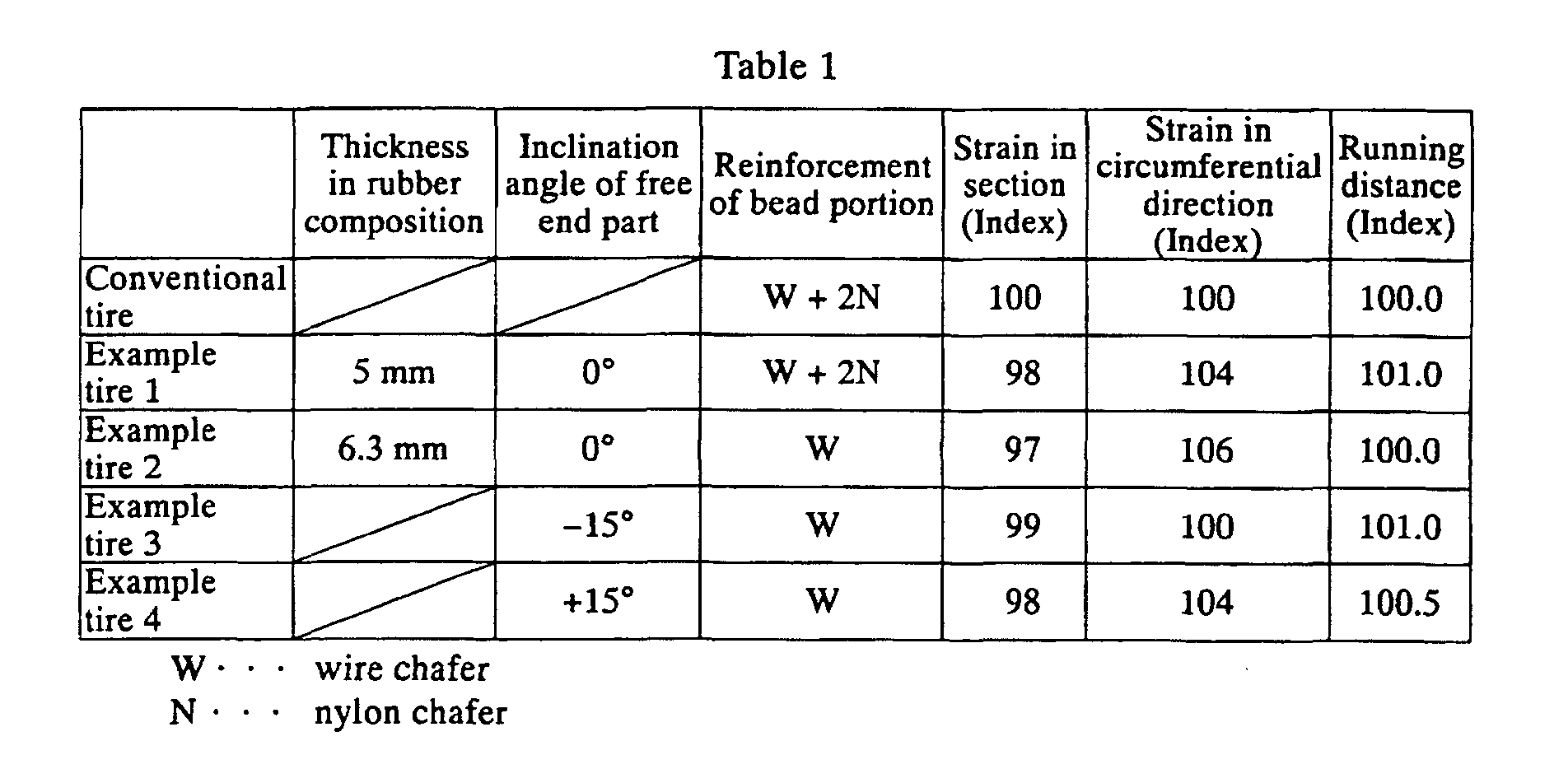
- Example tires 1 and 2 has a tire size of 315/60 R22.5 and comprise a bead portion having a winding structure shown in FIG. 2, in which the neighboring portion 4a to the winding end is extended at substantially a constant distance from the bead core surface, and the winding end 4b is positioned at a widthwise central portion of the bead core surface 2a and the distance therefrom to the main body portion of the carcass ply is 4 mm, and the thickness of the rubber composition located between the neighboring portion 4a and the bead core surface 2a and having a JIS A hardness of 60 is 5 mm and 6.3 mm, respectively, and Example tires 3 and 4 comprise a bead portion in which a winding embodiment of the winding portion is changed as shown in FIGS.
- Each of these tires is run at 60 km/h on a drum for a durability test under a maximum air pressure of 850kPa and a load of 117.6kN to measure a running distance until the tire brings about troubles.
- strain in the pulling-out direction at section of the winding end of the carcass ply is measured by a CT scan in the stop of the tire and further strain in the circumferential direction is measured from strain at the outside of the side portion.
- the conventional tire shown in the table has a bead portion structure shown in FIG. 1.
- numerical values in the table are represented by an index on the basis that the conventional tire is a control wherein the larger the measured value, the larger the index value.
- Example tires and Comparative tires is a tire having the structure of the aforementioned Example tire 1 as a basic structure and a distance of the winding end of the carcass ply to the bead core surface of 5 mm and a JIS A hardness of the rubber composition as a parameter, respectively, and the running distance, the strain in section and the strain in the circumferential direction thereof are measured in the same manner as mentioned above to obtain the results shown in Table 2.
- the conventional tire in Example 1 is a control in which the larger the measured value, the larger the index value.
- JIS A hardness Strain in section (Index) Strain in circumferential direction (Index) Running distance (Index) Comparative example tire 1 15 124 123 59 Comparative example tire 2 92 82 81 72 Example tire 5 40 104 106 100 Example tire 6 60 98 104 101 Example tire 7 80 90 89 100
- Example tires and Comparative tires is a tire having the structure of the above Example tire 1 as a basic structure and a JIS A hardness of the rubber composition of 60 and a distance of the winding end of the carcass ply to the bead core surface as a parameter, respectively, and the same measurements as in Example 1 are carried out to obtain the results shown in Table 3.
- Example tires and Comparative tires is a tire having the structure of the above Example tire 1 as a basic structure, a distance of the winding end of the carcass ply to the bead core surface of 5 mm and a JIS A hardness of the rubber composition of 60 and a distance from the winding end of the carcass ply to the main body of the carcass ply as a parameter, respectively, and the same tests as mentioned above are carried out to obtain the results shown in Table 4.
- the strain in section is decreased as the distance to the main body of the carcass ply becomes short.
- the pulling-out restraint layer of the carcass ply which may be made of the rubber composition, is arranged between the winding portion and the bead core, whereby the occurrence of the bead portion crack resulted from the winding of the side portion of the carcass ply to a higher position outward in the radial direction of the tire can be prevented but also the tensile force applied to the main body portion of the carcass ply can sufficiently be supported by the pulling-out restraint layer, and hence the pulling-out of the carcass ply can effectively be prevented.
Landscapes
- Engineering & Computer Science (AREA)
- Mechanical Engineering (AREA)
- Tires In General (AREA)
Abstract
Description
| JIS A hardness | Strain in section (Index) | Strain in circumferential direction (Index) | Running distance (Index) | |
| Comparative example tire 1 | 15 | 124 | 123 | 59 |
| | 92 | 82 | 81 | 72 |
| Example tire 5 | 40 | 104 | 106 | 100 |
| | 60 | 98 | 104 | 101 |
| | 80 | 90 | 89 | 100 |
| Distance to bead core surface | Strain in section (Index) | Strain in circumferential direction (Index) | Running distance (Index) | |
| | 9.0 mm | 106 | 107 | 90 |
| | 0.1 | 101 | 93 | 99 |
| Example tire 8 | 1.0 mm | 99 | 98 | 102 |
| Example tire 9 | 3.0 mm | 96 | 101 | 104 |
| Example tire 10 | 5.0 mm | 98 | 104 | 101 |
| Example tire 11 | 0.3 mm | 100 | 97 | 101 |
| Distance to main body portion | Strain in section (Index) | Strain in circumferential direction (Index) | Running distance (Index) | |
| Comparative example tire 5 | 0.08 | 102 | 99 | 98 |
| | 6 mm | 105 | 105 | 97 |
| Example tire 12 | 0.3 mm | 99 | 100 | 101 |
| Example tire 13 | 2 mm | 95 | 102 | 102 |
| Example tire 14 | 4 mm | 98 | 104 | 101 |
Claims (9)
- A pneumatic the comprising a pair of bead portions each including a bead core and a carcass ply extending between the bead cores and winding its side portion around the respective bead core, characterized in that a pulling-out restraint layer for the carcass ply is arranged between the bead core and a winding portion of the carcass ply.
- A pneumatic tire according to claim 1, wherein the pulling-out restraint layer is constituted by a rubber composition.
- A pneumatic tire according to claim 2, wherein the rubber composition has a JIS A hardness of 20-90.
- A pneumatic tire according to any one of claims 1 to 3, wherein a distance from a winding end of the carcass ply to a surface of the bead core opposite thereto is not less than 0.3 mm but not more than 7 mm.
- A pneumatic tire according to any one of claims 1 to 4, wherein the winding portion of the carcass ply is provided with one or more bending parts directing to a direction wound around the bead core.
- A pneumatic tire according to any one of claims 1 to 5, wherein a distance of radius from a center of the tire to the winding end of the carcass ply is not more than a distance of radius in a position located at an outermost side in the whole winding portion of the carcass ply in the radial direction of the tire.
- A pneumatic tire according to any one of claims 1 to 6, wherein a neighboring portion to the winding end of the carcass ply is extended at an approximately constant distance with respect to the surface of the bead core opposite thereto in the cross section of the bead portion.
- A pneumatic tire according to any one of claims 1 to 7, wherein a distance from the winding end of the carcass ply to a main body portion of the carcass ply extending between the bead cores is not less than 0.1 mm but not more than 5 mm.
- A pneumatic tire according to any one of claims 4 to 8, wherein the winding portion of the carcass ply is provided with one or more bending parts located approximately in correspondence to comer parts of the bead core having comer parts in its cross section.
Applications Claiming Priority (3)
| Application Number | Priority Date | Filing Date | Title |
|---|---|---|---|
| JP2001144294 | 2001-05-15 | ||
| JP2001144294 | 2001-05-15 | ||
| PCT/JP2002/004715 WO2002102612A1 (en) | 2001-05-15 | 2002-05-15 | Pneumatic tire |
Publications (3)
| Publication Number | Publication Date |
|---|---|
| EP1388435A1 true EP1388435A1 (en) | 2004-02-11 |
| EP1388435A4 EP1388435A4 (en) | 2006-04-19 |
| EP1388435B1 EP1388435B1 (en) | 2010-04-14 |
Family
ID=18990266
Family Applications (1)
| Application Number | Title | Priority Date | Filing Date |
|---|---|---|---|
| EP02726424A Expired - Lifetime EP1388435B1 (en) | 2001-05-15 | 2002-05-15 | Pneumatic tire |
Country Status (6)
| Country | Link |
|---|---|
| US (1) | US20040194864A1 (en) |
| EP (1) | EP1388435B1 (en) |
| JP (1) | JPWO2002102612A1 (en) |
| DE (1) | DE60235975D1 (en) |
| ES (1) | ES2341759T3 (en) |
| WO (1) | WO2002102612A1 (en) |
Cited By (2)
| Publication number | Priority date | Publication date | Assignee | Title |
|---|---|---|---|---|
| EP1479537A3 (en) * | 2003-05-13 | 2005-02-02 | Sumitomo Rubber Industries Limited | Pneumatic tire |
| US7712501B2 (en) * | 2004-08-06 | 2010-05-11 | Sumitomo Rubber Industries, Ltd. | Heavy duty tire |
Families Citing this family (7)
| Publication number | Priority date | Publication date | Assignee | Title |
|---|---|---|---|---|
| JP3802515B2 (en) * | 2003-05-30 | 2006-07-26 | 住友ゴム工業株式会社 | Heavy duty tire |
| CN100366450C (en) * | 2003-08-26 | 2008-02-06 | 住友橡胶工业株式会社 | Heavy duty tire |
| US7152646B2 (en) * | 2003-10-07 | 2006-12-26 | Sumitomo Rubber Industries, Ltd. | Heavy duty tire |
| US7165590B2 (en) * | 2003-11-26 | 2007-01-23 | Sumitomo Rubber Industries, Ltd. | Heavy duty pneumatic radial tire with carcass ply winding-up portion |
| JP3902177B2 (en) * | 2003-12-10 | 2007-04-04 | 住友ゴム工業株式会社 | Heavy duty tire |
| JP3890050B2 (en) * | 2003-12-22 | 2007-03-07 | 住友ゴム工業株式会社 | Heavy duty tire |
| FR2912346B1 (en) * | 2007-02-12 | 2009-04-24 | Michelin Soc Tech | TIRE BOURRELET STRUCTURE |
Family Cites Families (8)
| Publication number | Priority date | Publication date | Assignee | Title |
|---|---|---|---|---|
| JP3643191B2 (en) * | 1995-11-29 | 2005-04-27 | 株式会社ブリヂストン | 15 ° tapered radial tire for trucks and buses |
| JP2855327B2 (en) * | 1987-12-15 | 1999-02-10 | 横浜ゴム株式会社 | Pneumatic radial tire |
| US5885387A (en) * | 1995-12-08 | 1999-03-23 | Sumitomo Rubber Industries, Ltd. | Pneumatic tire having endless carcass cord ply |
| JP3613653B2 (en) * | 1996-10-15 | 2005-01-26 | 東洋ゴム工業株式会社 | Heavy duty pneumatic radial tire |
| JP4293658B2 (en) * | 1998-11-11 | 2009-07-08 | 株式会社ブリヂストン | Heavy duty pneumatic radial tire |
| JP4354569B2 (en) * | 1999-04-23 | 2009-10-28 | 株式会社ブリヂストン | Heavy duty pneumatic radial tire |
| EP1024033B1 (en) | 1999-01-28 | 2005-06-01 | Bridgestone Corporation | Pneumatic tires |
| JP4213811B2 (en) * | 1999-04-23 | 2009-01-21 | 株式会社ブリヂストン | Pneumatic radial tire |
-
2002
- 2002-05-15 WO PCT/JP2002/004715 patent/WO2002102612A1/en not_active Ceased
- 2002-05-15 JP JP2003505172A patent/JPWO2002102612A1/en active Pending
- 2002-05-15 EP EP02726424A patent/EP1388435B1/en not_active Expired - Lifetime
- 2002-05-15 ES ES02726424T patent/ES2341759T3/en not_active Expired - Lifetime
- 2002-05-15 DE DE60235975T patent/DE60235975D1/en not_active Expired - Lifetime
- 2002-05-15 US US10/477,715 patent/US20040194864A1/en not_active Abandoned
Cited By (3)
| Publication number | Priority date | Publication date | Assignee | Title |
|---|---|---|---|---|
| EP1479537A3 (en) * | 2003-05-13 | 2005-02-02 | Sumitomo Rubber Industries Limited | Pneumatic tire |
| US7152647B2 (en) | 2003-05-13 | 2006-12-26 | Sumitomo Rubber Industries, Ltd. | Pneumatic tire |
| US7712501B2 (en) * | 2004-08-06 | 2010-05-11 | Sumitomo Rubber Industries, Ltd. | Heavy duty tire |
Also Published As
| Publication number | Publication date |
|---|---|
| JPWO2002102612A1 (en) | 2004-09-30 |
| DE60235975D1 (en) | 2010-05-27 |
| US20040194864A1 (en) | 2004-10-07 |
| ES2341759T3 (en) | 2010-06-28 |
| EP1388435A4 (en) | 2006-04-19 |
| WO2002102612A1 (en) | 2002-12-27 |
| EP1388435B1 (en) | 2010-04-14 |
Similar Documents
| Publication | Publication Date | Title |
|---|---|---|
| JP3117645B2 (en) | Pneumatic radial tire | |
| JP5049050B2 (en) | Heavy duty tire | |
| JP3437235B2 (en) | Aircraft radial tires | |
| US20070113944A1 (en) | Pneumatic tire | |
| JPH0133362B2 (en) | ||
| US6478064B1 (en) | Heavy duty radial tire with chafer height greater than bead apex height | |
| US6257290B1 (en) | Low-aspect tire | |
| EP2322360B1 (en) | Heavy duty tire | |
| US6079467A (en) | Heavy duty radial tire with specified arrangement of chafer and carcass turnup | |
| US20210309053A1 (en) | Pneumatic Tire | |
| JP2002205508A (en) | Pneumatic tire | |
| US20040194864A1 (en) | Pneumatic tire | |
| EP2610074A1 (en) | Pneumatic radial aircraft tire | |
| EP0844109B1 (en) | Heavy duty radial tyre | |
| EP1116605B1 (en) | Pneumatic tire, having improved bead portion durability | |
| EP0313500A1 (en) | Pneumatic tires | |
| US6145560A (en) | Heavy duty pneumatic radial tires with specified belt cushion rubbers | |
| EP0698513B1 (en) | Pneumatic radial tires | |
| US6276416B1 (en) | Run-flat tire with pair of rigid rings in shoulders inside carcass | |
| JP4625319B2 (en) | Pneumatic tire and manufacturing method thereof | |
| US5769983A (en) | Pneumatic radial tires provided with a side portion reinforcing layer | |
| US4770221A (en) | Heavy duty pneumatic radial tire | |
| US5151139A (en) | Heavy duty radial tire having durable buttress portion | |
| US7493928B2 (en) | Heavy duty tire | |
| JP3670417B2 (en) | High performance flat radial tire |
Legal Events
| Date | Code | Title | Description |
|---|---|---|---|
| PUAI | Public reference made under article 153(3) epc to a published international application that has entered the european phase |
Free format text: ORIGINAL CODE: 0009012 |
|
| 17P | Request for examination filed |
Effective date: 20031118 |
|
| AK | Designated contracting states |
Kind code of ref document: A1 Designated state(s): AT BE CH CY DE DK ES FI FR GB GR IE IT LI LU MC NL PT SE TR |
|
| AX | Request for extension of the european patent |
Extension state: AL LT LV MK RO SI |
|
| A4 | Supplementary search report drawn up and despatched |
Effective date: 20060308 |
|
| 17Q | First examination report despatched |
Effective date: 20070913 |
|
| GRAP | Despatch of communication of intention to grant a patent |
Free format text: ORIGINAL CODE: EPIDOSNIGR1 |
|
| RBV | Designated contracting states (corrected) |
Designated state(s): DE ES FR GB IT |
|
| GRAS | Grant fee paid |
Free format text: ORIGINAL CODE: EPIDOSNIGR3 |
|
| GRAA | (expected) grant |
Free format text: ORIGINAL CODE: 0009210 |
|
| AK | Designated contracting states |
Kind code of ref document: B1 Designated state(s): DE ES FR GB IT |
|
| REG | Reference to a national code |
Ref country code: GB Ref legal event code: FG4D |
|
| REF | Corresponds to: |
Ref document number: 60235975 Country of ref document: DE Date of ref document: 20100527 Kind code of ref document: P |
|
| REG | Reference to a national code |
Ref country code: ES Ref legal event code: FG2A Ref document number: 2341759 Country of ref document: ES Kind code of ref document: T3 |
|
| PLBE | No opposition filed within time limit |
Free format text: ORIGINAL CODE: 0009261 |
|
| STAA | Information on the status of an ep patent application or granted ep patent |
Free format text: STATUS: NO OPPOSITION FILED WITHIN TIME LIMIT |
|
| 26N | No opposition filed |
Effective date: 20110117 |
|
| PGFP | Annual fee paid to national office [announced via postgrant information from national office to epo] |
Ref country code: GB Payment date: 20120509 Year of fee payment: 11 |
|
| PGFP | Annual fee paid to national office [announced via postgrant information from national office to epo] |
Ref country code: IT Payment date: 20120517 Year of fee payment: 11 |
|
| PGFP | Annual fee paid to national office [announced via postgrant information from national office to epo] |
Ref country code: ES Payment date: 20120518 Year of fee payment: 11 |
|
| GBPC | Gb: european patent ceased through non-payment of renewal fee |
Effective date: 20130515 |
|
| PG25 | Lapsed in a contracting state [announced via postgrant information from national office to epo] |
Ref country code: IT Free format text: LAPSE BECAUSE OF NON-PAYMENT OF DUE FEES Effective date: 20130515 |
|
| PG25 | Lapsed in a contracting state [announced via postgrant information from national office to epo] |
Ref country code: GB Free format text: LAPSE BECAUSE OF NON-PAYMENT OF DUE FEES Effective date: 20130515 |
|
| REG | Reference to a national code |
Ref country code: ES Ref legal event code: FD2A Effective date: 20140612 |
|
| REG | Reference to a national code |
Ref country code: DE Ref legal event code: R082 Ref document number: 60235975 Country of ref document: DE Representative=s name: MARKS & CLERK (LUXEMBOURG) LLP, LU |
|
| PG25 | Lapsed in a contracting state [announced via postgrant information from national office to epo] |
Ref country code: ES Free format text: LAPSE BECAUSE OF NON-PAYMENT OF DUE FEES Effective date: 20130516 |
|
| REG | Reference to a national code |
Ref country code: FR Ref legal event code: CA Effective date: 20140812 |
|
| REG | Reference to a national code |
Ref country code: DE Ref legal event code: R081 Ref document number: 60235975 Country of ref document: DE Owner name: BRIDGESTONE CORPORATION, JP Free format text: FORMER OWNER: BRIDGESTONE CORP., TOKIO/TOKYO, JP Effective date: 20140828 Ref country code: DE Ref legal event code: R082 Ref document number: 60235975 Country of ref document: DE Representative=s name: MARKS & CLERK (LUXEMBOURG) LLP, LU Effective date: 20140828 |
|
| REG | Reference to a national code |
Ref country code: FR Ref legal event code: PLFP Year of fee payment: 15 |
|
| REG | Reference to a national code |
Ref country code: FR Ref legal event code: PLFP Year of fee payment: 16 |
|
| REG | Reference to a national code |
Ref country code: FR Ref legal event code: PLFP Year of fee payment: 17 |
|
| PGFP | Annual fee paid to national office [announced via postgrant information from national office to epo] |
Ref country code: DE Payment date: 20190521 Year of fee payment: 18 |
|
| PGFP | Annual fee paid to national office [announced via postgrant information from national office to epo] |
Ref country code: FR Payment date: 20190522 Year of fee payment: 18 |
|
| REG | Reference to a national code |
Ref country code: DE Ref legal event code: R119 Ref document number: 60235975 Country of ref document: DE |
|
| PG25 | Lapsed in a contracting state [announced via postgrant information from national office to epo] |
Ref country code: FR Free format text: LAPSE BECAUSE OF NON-PAYMENT OF DUE FEES Effective date: 20200531 |
|
| PG25 | Lapsed in a contracting state [announced via postgrant information from national office to epo] |
Ref country code: DE Free format text: LAPSE BECAUSE OF NON-PAYMENT OF DUE FEES Effective date: 20201201 |